Tri-Band Slot-Loaded Microstrip Antenna for Internet of Things Applications
←
→
Page content transcription
If your browser does not render page correctly, please read the page content below
Tri-Band Slot-Loaded Microstrip Antenna
for Internet of Things Applications
Shereen Mohamed-Refaat 1, Ahmed Abdelaziz 2*, and Ehab K. I. Hamad 1
1
    Dept. of Electrical Engineering, Faculty of Engineering, Aswan University, Aswan 81542, Egypt
2
    Dept. of Electronics & Comm., Luxor Higher Institute of Engineering & Technology, Luxor 85834, Egypt

Corresponding author: (e-mail: d20190014@aswu.edu.eg).

ABSTRACT A new design of a multiband microstrip patch antenna using slots in the patch as well as
defected ground structures (DGS) implemented in the ground plane is proposed. Multi resonance response
was obtained by etching the DGS shapes in the ground plane of a traditional patch operates at 5.2 GHz,
which is the common frequency for the Internet of Things (IoT) applications. The novel outcome of this
work is a compact antenna that resonates at three bands, viz. 2.42, 5.22 and 5.92 GHz. Different shapes of
slots were used to improve the antenna performance at the different resonances. The antenna uses the inset
feeding technique to improve impedance matching. Rogers RO3003 substrate of 3 relative dielectric
constant, 0.0013 loss tangent, and 1.5 mm thickness is used to build the antenna. The designed antenna is
simulated using HFSS software. The good consistency between simulations and measurements confirms the
antenna's ability to improve the benefits for IoT applications at three different frequencies.

INDEX TERMS: Multiband antenna, DGS, Internet of Things, IoT, Slotted patch

I. INTRODUCTION                                                                          There are various bandwidth and gain enhancement
                                                                                         techniques such as loading of different slot shapes and sizes
Rapid evolution of communications and the ever-increasing
                                                                                         [4], notches on the patch or in the ground plane and the
demand for wireless access have the world focused on
                                                                                         adoption of metamaterials (MTM) in their fabrication [5]. A
proper utilization of the sub-GHz band for the design of
                                                                                         U-shape structure is being used for designing a microstrip
antennas that fit smaller devices and that provide wider
                                                                                         patch antenna with resonating frequency in the range of S
bandwidth [1]. The Internet of Things (IoT) encompasses
                                                                                         band, various slot shapes are used to shift the resonating
major progress in computer networking, microelectronics
                                                                                         frequency range to L-band [6]. Another microstrip patch
and contemporary communication systems. This
                                                                                         antenna is modified in two steps: first by adding two rook
technology enables the remote control of physical sensors
                                                                                         slots to the patch plane and second by two semi ellipses on
and actuators over the internet. These devices must be
                                                                                         both bottom edges of the radiating element [1]. A number of
compact, economical and energy efficient to operate on the
                                                                                         researchers have reported microstrip patch antennas for IoT
multiband for LTE, WLAN (IEEE 802.11 a/b/g/n),
                                                                                         applications such as a microstrip line fed truncated
WiMAX (IEEE 802.16), ZigBee (IEEE802.15.4) and GSM
                                                                                         icosidodecahedron modeled antenna [7]. Also, etching
(800MHz, 850MHz, and 1900MHz) [2]. In order to ensure                                    defected ground structures (DGS) of a simple shape in the
reliable communication. The IoT reporting on these                                       ground plane, or a complicated shape for the better
categories is reflected in the increase in the world                                     performance [8, 9, 10], and use of a metamaterial split ring
population and the number of connected devices. The                                      resonator [11, 12] have been reported in recent literatures.
world's population in 2003 stood at 6.3 billion people with                              This paper describes a new design of microstrip patch
0.08 percent linked equipment per person, while these                                    antenna where a DGS was loaded on the ground plane to
figures were increased respectively to 7.2 billion and 3.4                               generate multiple resonance frequencies for different
percent in 2015. It is anticipated that this trend will grow                             applications in IoT bands. Additional slots with various
exponentially, which will increase the demand for smaller                                shapes were introduced in the conventional patch to
devices along with the better antenna module. Owing to                                   increase the initial patch resonance. The position and
miniaturization of embedded systems, multiple modules can                                dimensions of the modifications were set to obtain
be installed on these small gadgets in order to improve                                  minimum return loss and the highest possible gain. The
efficiency, reliability and strength to fit different                                    conventional patch antenna was chosen as a reference
environmental scenarios, intelligent cities, intelligent health                          antenna to operate at 5.2 GHz for IoT band applications.
care, smart grids, military / security, etc. [3].                                        The designed antenna was optimized to resonate at the
Narrow bandwidth and low gain are considerable problems                                  Bluetooth, Zigbee and Wi-Fi bands (2.42, 5.22 and 5.92
of microstrip patch antennas that restrict their applications.                           GHz). Simulations and experimental measurements were
                                                                                         carried out for verification and confirmation of the designed
                                                                                         antenna where good agreement between the results served
                                                                                         as validation.

VOL. 10, NO. 1, MARCH 2021                                                                                                                       21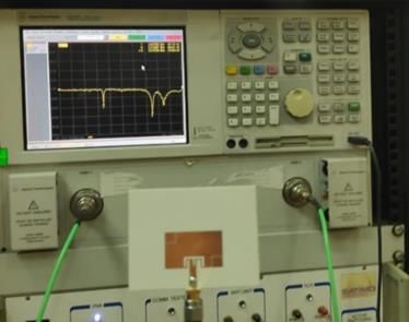
S. Mohamed-Refaat et al.
II. ANTENNA CONFIGURATION DGS for proper operation. Additional DGS in the next
We present, first, a DGS inspired rectangular microstrip stages were intended to improve the performance of the
patch antenna. A traditional 5.2 GHz patch antenna was antenna at the specific resonant frequency created above.
selected as a reference antenna for the first time. The Stage 2 had the objective of improving the reflection
designed reference antenna has a width and length of 15.75 coefficient of the first resonance at 2.4 GHz. This was done
and 25.5 mm, respectively, and a copper thickness of 35 by etching two nested U- and L-shaped slots at the top-left
μm. The patch radiator has been printed on a 1.5 mm and bottom-right corners of the radiating element. The
thickness substrate (Ԑr = 3, tan δ = 0.0013) of Roger Ro positions of the two slots at the edges of the patch were
3003 as displayed in Fig. 1(a). A 50 Ω microstrip inset feed chosen based on the concept of fringing fields. The
of 3 mm width and 12 mm length was introduced to resulting antenna worked well, showing good performance
perfectly matching the antenna. The feed line was inset to at 2.4 GHz. In Stage 3, an additional E-shaped slot was
the patch with a value of Y0 = 3.5 mm. The inset feed line etched in the patch as illustrated in Fig. 2(c). This slot was
was separated from the patch by two gaps, viz. W01 = 2.5 optimized to improve considerably the antenna
mm and W02 = 0.5 mm as shown in Fig. 1(a). The reference performance at the three resonant frequencies at 2.4, 5.19
antenna was optimized for a reasonable gain of 7.86 dB. and 5.9 GHz for IoT applications. All three stages were
The reflection coefficient, S11 of the antenna is depicted in simulated, and the reflection coefficients are displayed in
Fig. 1(b) where it can be observed that the antenna Fig. 2(d).
resonated at 5.2 GHz.
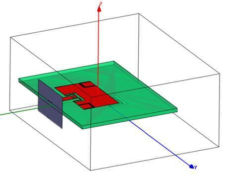
The boundaries had to be set as shown in Fig. 3 to verify
and to extract the scattering parameters of this proposed
antenna. Perfect magnetic conductor (PMC) boundary
conditions were set on the left and right walls of the air box,
and perfect electric conductor (PEC) boundary conditions
were set on the top and bottom of the air box [13]. In order
to identify the resonant frequencies and the effective
parameters derived from DGS and slot, scattering
parameters were calculated over an acceptable frequency
range. The E-field of the incident wave was polarized along
the z-axis, and the H-field was polarized along the x-axis
[14]. The optimal dimensions of the designed antenna, DGS
(a) as well as the slots are listed in Tab. 1. The incident TEM
wave propagated in the direction of the y-axis.
(a)
(b)
FIGURE 1. Conventional microstrip antenna operating at 5.2 GHz (a)
Schematic diagram, (b) Simulated S11 parameter
A. Development of the Proposed Antenna
Different developmental stages of the proposed antenna are
shown in Fig 2(a) to (c). Initially in Stage 1, two nested
gaped-rectangular slots were implemented as a defected
ground structure in the ground plane to create additional
resonant frequencies. The selected position of the DGS was
dependent on the current distribution within the ground
plane. The dimensions of the DGS were optimized to set
the resonant frequencies at the desired frequency bands and (b)
to minimize the reflection coefficient (S11). The parametric
study in this stage indicated how the size of the DGS
affected the resonance frequencies and the S11 result, as
shown in Fig. 2(d), to determine the definite size of the
VOL. 10, NO. 1, MARCH 2021
22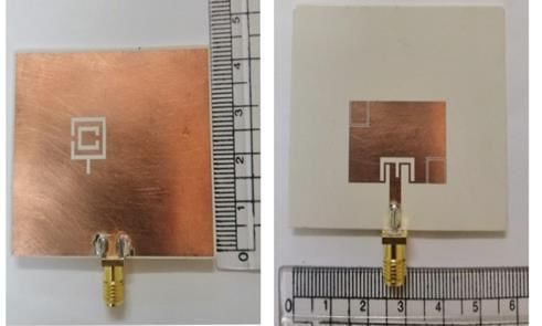
into the radiating element was to achieve good performance
                                                                           of the proposed antenna at the three resonant frequencies.
                                                                           The schematic diagrams of the proposed slots are shown in
                                                                           Fig. 4(b) and (c). Optimized values of the proposed antenna
                                                                           dimensions including the created DGS and slots are listed
                                                                           in Table I.

                                    (c)

                                                                                                                (a)

                                    (d)
FIGURE 2. Development of proposed antenna. (a) Stage 1, (b) Stage 2, (c)
Stage 3, and (d) S-parameters of different stages.

                                                                                                                (b)

FIGURE 3. Microstrip patch setup for transmission analysis.

B.         DGS and Slots

This section describes in detail the influence of the                                                           (c)
geometrical parameters of the DGS implemented in the
                                                                            FIGURE 4. Schematic diagrams of the (a) Rectangular DGS, (b) E-slot in
ground plane and of the slots implemented as a radiating                        the patch of antenna, and (c) U-L-slots in the patch of antenna
element on the antenna performance. The aim of etching
the DGS in the ground plane was to create additional
resonant frequencies at 2.44 GHz and 5.9 GHz. The
schematic diagram of the rectangular DGS is shown in Fig.
4(a). The objective of adding two different shapes of slots

VOL. 10, NO. 1, MARCH 2021                                                                                                                           23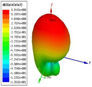
S. Mohamed-Refaat et al.

TABLE I. Optimal values of the proposed antenna parameters
     Parameter       Value(mm)          Parameter            Value(mm)
        Lp             15.75                r                   3
        wp             25.5                g                    1
        Lf              12                 wE                  4.5
       wf                3                  LE                  9
       wo1              2.5                SE                   1
       wo2              0.5                SEE                 0.8
       Yo               3.5                wEE                 2.8
        L                9                 wu                  4.6
        w               10                 Lu                  4.6
        s               0.2                Su                  0.2
        F                1                 LL                   5
       wL               5.2

                                                                         FIGURE 5. S-parameters of CSRR and DGS where the stub is jointed to the
                                                                         CSRR

III. PARAMETRIC STUDY
                                                                              B. U- and L-Shaped Slots
A full parametric study was carried out in order to examine
                                                                         The parametric study in this stage shows how the position
the effects of the geometrical variables in the proposed
                                                                         of U and L slots (keeping their dimensions constant) would
design in order to identify evaluation parameters, determine
                                                                         affect the resonant frequency at 2.45 GHz to determine the
each parameter range, define design limitations and analyze
                                                                         best position for proper operation of the slots. The
the result of each parameter variation. Once configurations
                                                                         placement of the slots inside the patch varied from x = -2.8
were developed, our simulations were tested before the
                                                                         mm to 12.8 mm along x-axis direction where x = 0, y = 0
parameters were further refined according to design
                                                                         was the reference point where the patch was centered. For
constraints until the results were satisfactory. First of all,
                                                                         the y-direction, the best position of the slots at the edges of
the feeding line location was designed to perfectly match
                                                                         the patch was selected based on the fringing field theory.
the transmission line to the patch. The center of the patch is
                                                                         The design of the patch with DGS could only achieve 1.5
taken as a reference point for all axes (x = 0, y = 0). The
                                                                         dBi peak realized gain, so U and L slots were used in order
ground plane length was then modified so as to reach the
                                                                         to much enhance the reflection coefficient and the gain at
widest bandwidth possible. The optimized design without
                                                                         2.45 GHz. It should be noted that the parametric studies at
further development is illustrated in Fig. 1. Each DGS and
                                                                         this stage were carried out twice, alternately for slots on the
slot form has subsequently been individually studied.
                                                                         right side and then on the left side. The best location of
       A. Defected Ground Structure                                      slots on the right side in x-direction was at xr = 12.8 mm and
                                                                         the optimal value obtained on the left side was at xl = -2.8
The commonly used structures of metamaterial are Split                   mm.
Ring Resonators (SRRs) and Complementary Split Ring
Resonators (CSRRs). The effects of inserting CSRR in the
ground plane of a microstrip patch antenna on the return
loss, radiation pattern and magnetic field were evaluated
with respect to the variations in the CSRR dimensions [15].
Metamaterial structures can be designed in many ways and
the introduction of DGS on the ground plane effectively
increases the inductance and capacitance of the overall
electric circuits [16]. In the present study, DGS was
incorporated in the ground as illustrated in Fig. 2(a) to
provide a satisfactory response for the new resonant
frequencies. The CSRR structure shown in Fig. 4(a) is
modified by incorporating an open-circuited stub joint to
that CSRR. The influence of the position where the stub is
joint; left, right or centered on the edge of the CSRR in                 FIGURE 6. Parametric study for the second stage, operating at 2.45 GHz,
terms of the reflection coefficient are investigated in Fig. 5.                                positioned in the x direction

24                                                                                                                     VOL. 10, NO. 1, MARCH 2021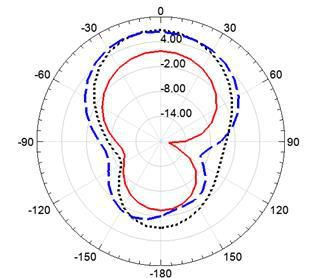
FIGURE 7. Current distribution over the radiating element
                               at 5.2 GHz.
                                                                                                          (b)
     C.     E-Shaped Slots                                            FIGURE 8. EM simulation results of the proposed final design, (a) S11,
                                                                      and (b) VSWR
An additional, E-shaped slot etched within the radiating
patch to further improve the S-parameter at the second
resonance (5.2 GHz) was introduced. The position of the E-
shaped slot based on the current distribution was optimized
to a location closer to the feed line as depicted in Fig. 2(c).
Figure 7 shows the current distribution over the radiating
element at 5.2 GHz. Figure 2(c) illustrates how the U and E
slots were etched in the design. The simulated return loss of
this step is displayed in Fig. 2(d).

IV. SIMULATION RESULTS
All slots were integrated in the radiating element and the
DGS in the ground plane as shown in Fig. 2(c) to optimize
impedance matching at all resonances and, hence, the                                                      (a)
performance of the final design in achieving the triple band
behavior. The proposed antenna was simulated using the
3D EM full-wave simulator HFSS according to the finite
element method. The reflection coefficient and the voltage
standing wave ratio (VSWR) of the proposed antenna are
illustrated in Fig. 8(a) and (b), respectively. As observed
from the figures, the designed antenna operated at three
resonant frequencies, viz. 2.44, 5.19, and 5.9 GHz suited
for IoT applications. The optimized reflection coefficients
magnitudes were less than -33.9 dB at 2.44 GHz, less than -
39.5 dB at 5.19 GHz and less than -24.7 dB at 5.9 GHz.
The VSWR was very close to one at the three resonances of
interest.
                                                                                                          (b)
                                                                                         @ 2.44 GHz             @ 5.19 GHz               @ 5.9 GHz

                                                                      FIGURE 9. Radiation pattern of the proposed antenna at (a) phi = 0°,
                                                                      and (b) phi = 90°

                                    (a)

VOL. 10, NO. 1, MARCH 2021                                                                                                                       25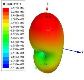
S. Mohamed-Refaat et al.

                                                                        V. FABRICATION AND MEASUREMENTS

                                                                        The proposed triple-band antenna was fabricated and tested
                                                                        to validate the simulation results. A photograph of the
                                                                        measurement setup is shown in Fig. 11(a) where the
                                                                        antenna is connected to a vector network analyzer (VNA) to
                                                                        measure the S-parameters and the VSWR. Photographs of
                                                                        the prototype for the fabricated antenna with triple-band
                                                                        response for IoT applications are shown in Fig. 11(b). Fig.
                                                                        11(c) depicts the measured S-parameter compared to the
                                                                        EM simulation. It can be observed that the fabricated model
                                                                        resonates at 2.42, 5.22 and 5.92 GHz. The measurement
                                                                        results were fairly consistent with the simulated results as
                                                                        shown in the comparison summarized in Table 2.
                               (a) at 2.44GHz

                                                                                                          (a)
                             (b) at 5.19GHz

                              (c) at 5.9GHz                                                               (b)
FIGURE 10. 3-D polar plots of the gain of the proposed antenna at the
resonant frequencies.

The radiation patterns at the E- and H-planes of the
proposed antenna are almost quasi-Omnidirectional
radiating patterns at 2.44, 5.19 and 5.9 GHz. The simulated
results are displayed in Fig. 9 (a) and (b). As observed from
the graphs; the radiation patterns at the three resonance
frequencies were quite similar in terms of stability
impression. In Fig. 10, the 3D polar plots of the antenna
gain at the three resonant frequencies are illustrated. It is
apparent that the directivity of the proposed antenna would
make it a good candidate for IoT applications.
                                                                                                          (c)
                                                                        FIGURE 11. (a) Measurement setup, (b) Top and bottom views of the
                                                                        prototype, (c) Measured and simulated S-parameters

26
                                                                                                                        VOL. 10, NO. 1, MARCH 2021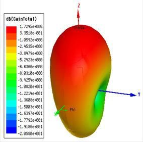
TABLEI I.: Comparison between simulated and fabricated antenna

                                                       Reference              Proposed antenna                    Proposed antenna
                                                        antenna                  (Simulations)                     (Measurements)
                Resonant Frequency GHz                    5.2            2.44        5.19      5.9             2.42     5.22     5.92
                             S11                         -29.7          -33.9           -39.5       -24.7      -14.9      -29.7      -17.7
                         Gain(dB)                        7.86            1.72           6.54         6.97      2.48       7.17       8.18

As seen in Fig. 12 the measured radiation pattern of E- and
H-planes of the proposed antenna at the three frequencies                       TABLE III. Comparison of the proposed antenna with other prototypes
are mostly Omni-directional patterns with little ripples.
                                                                                  Ref.          Operating              Peak          Dimensions (mm)
                                                                                                frequency (GHz)        gain(dBi)
                                                                                  [5]           0.78, 2.41,3.22,       7.44          110×90×6.35
                                                                                                4.83,5.83
                                                                                  [17]          1.8,5.2, 7,            1.52          30×20×1.52
                                                                                                7.86,8.53
                                                                                  [18]          2.38, 1.53             2.5           110×65×1.6
                                                                                  This          2.42,5.22, 5.92        8.18          55.5×42.75×1.5
                                                                                  work

                                                                                VI. CONCLUSION
                       (a) E & H planes at 2.42 GHz
                                                                                This paper proposed a triple-band antenna for IoT
                                                                                applications. It is designed and constructed based on DGS
                                                                                and slots structure techniques. The proposed antenna is
                                                                                compatible with Bluetooth, WLAN, Wi-Fi, Zigbee and
                                                                                other standards of the IoT system. The effects of the DGS
                                                                                and slots on the antenna performance are greatly depending
                                                                                on the position within the radiating element. The antenna
                                                                                was printed on the low loss Rogers Ro3003 substrate of er =
                                                                                3-, and 1.5-mm thickness. Good matching between the
                                                                                measured and simulated results was achieved.
                       (b) E & H planes at 5.22 GHz
                                                                                ACKNOWLEDGMENT
                                                                                The authors would like to thank Eng. Nagdy of the NTI
                                                                                Institute, Cairo, Egypt, for his help in fabricating the
                                                                                proposed models. Thanks go also to Eng. Mohamed
                                                                                Abdelaziz for his support in the measurements of radiation
                                                                                characteristics of the fabricated models at the Science and
                                                                                Technology Center of Excellence in Cairo, Egypt.

                                                                                References
                                                                                [1] M. Mokayef, M. A. Summakieh, "An Ultra-Widwband for
                        (c) E & H planes at 5.92 GHz                                IoT Connectivity," International Journal of Internet of
                        E plane        ---- H Plane                                 Things and Web Services, Vol .2, pp. 76-79, 2017.
                                                                                [2] Q. Awais, H. T. Chattha, ''A Novel Dual Ultrawideband
FIGURE 12. Measured E- and H-planes radiation patterns at the                       CPW-Fed Printed Antenna forInternet of Things (IoT)
three frequencies of the triple band antenna.                                       Applications,'' Wireless Communications and Mobile
                                                                                    Computing, Vol. 2018, pp. 1-9, Mar. 2018.
                                                                                [3] D. Acharjya, M. K. Geetha, “Internet of Things: Novel
Table III presents a comparison of the proposal antenna                             Advances and Envisioned Applications,” Springer
                                                                                    International Publishing, 2017.
with the other literature designs in terms of operating
                                                                                [4] A. Abdelaziz, E. K. I. Hamad, “Design of a Compact High
frequencies, peak gain and size for determining the validity                        Gain Microstrip Patch Antenna for Tri-Band 5G Wireless
of the proposed triple-band antenna. This comparison                                Communication,” Frequenz, Vol. 73, Issue 1-2, pp. 45-52,
indicates that the proposed antenna is more beneficial than                         January 2019.
other antennas, although in some cases the current design is
smaller.

VOL. 10, NO. 1, MARCH 2021                                                                                                                            27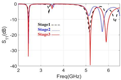
S. Mohamed-Refaat et al.

[5] E. K. I. Hamad, G. Nady, “Bandwidth Extension of Ultra-
    wideband Microstrip Antenna Using Metamaterial Double-
    side Planar Periodic Geometry,” Radioengineering, Vol. 28,
    No. 1, pp. 25-32, April 2019.
[6] A. Satheesh, R. Chandrababu, and I. S. Rao, “A Compact
    Antenna for IoT Applications”, IEEE, 2017 International
    Conference on tnnovations in Information, Embedded and
    Communication Systems (ICIIECS),17-18 March 2017,
    Coimbatore, India.
[7] V. Das, T. Shanmuganantham, ''Design of Multiband
    Microstrip Patch Antenna For IOT Applications'', IEEE
    International Conference on Circuits and Systems (ICCS),
    20-21 Dec. 2017, Thiruvananthapuram, India.
[8] R. Er-rebyiy, J. Zbitou, A. Tajmouati, M. Latrach, A. Errkik,
    and L. El Abdellaoui, ''A New Design of a Miniature
    Microstrip Patch Antenna Using Defected Ground Structure
    DGS'', International Conference on Wireless Technologies,
    Embedded and Intelligent Systems (WITS), 19-20, April
    2017, Fez, Morocco.
[9] B. T. P. Madhav, S. Rajiya, B. P. Nadh, and M. S. Kumar,
    "Frequency reconfigurable monopole antenna with DGS for
    ISM band applications," Journal of Electrical Engineering,
    Vol 69, no. 4,2018.
[10] L. Wu, F. Wan, W. Rahajandraibe, S. Lalléchère and B. Ravelo, “On
     the investigation of contactless bandpass NGD control with
     microstrip patch-based circuit,” Journal of Electromagnetic Waves
     and Applications, Vol. 34, no. 14, pp. 1849-1857, 2020.
[11] A. Sabban, ''Small New Wearable Antennas for IOT, Medical
       and Sport Applications'', IEEE 13th European Conference on
       Antennas and Propagation (EuCAP 2019), 31 March-5 April
       2019, Krakow, Poland, Poland.
[12]   P. Bora, C. Paul, "Metamaterial Loaded CSRR Based
       Antenna For WLAN And IOT BAND Applications",
       International Journal of Scientific & Technology Research,
       Vol. 8, Issue 09, September 2019.
[13]   W. Ali, E. K. I. Hamad, M. Bassiuny and M. Z. M.
       Hamdalla, “Complementary Split Ring Resonator Based
       Triple Band Microstrip Antenna WLAN/WiMAX
       Applications,” Radioengineering, Vol. 26, No. 1, April 2017.
[14]   E. K. I. Hamad and M. Z. M. Hamdalla,''Design of a
       Compact Dual-Band Microstrip Antenna Enabled by
       Complementary Split Ring Resonators for X-Band
       Applications'', Advanced Electromagnetics, Vol. 7, No. 3, pp.
       82-86, August 2018.
[15]   I. B. T. da Silva, H. D. de Andrade, J. L. da Silva, "Effects of
       Complementary Split Ring Resonator (CSRR) Parameters in
       Microstrip Patch Antenna Characteristics",SBMO/IEEEMTT-
       SInternational Microwav and        Optoelectronics
       Conference (IMOC), 3-6 Nov. 2015, Porto de Galinhas,
       Brazil.
[16]    V. G. Ajay, A. R. Parvathy, and T. Mathew, "Microstrip
       antenna with DGS based on CSRR array for WiMAX
       applications", International Journal of Electrical and
       computer Engineering (IJECE), Vol. 9, No. 1, Feb. 2019.
[17]   S. K. Das, and T. Shanmuganantham, “Design of Triple
       Starfish Shaped Microstrip Patch Antenna for IoT
       Application”, 2017 IEEE International Conference on
       Circuits and Systems (ICCS), 20-21 Dec. 2017.
       Thiruvananthapuram, India.
[18]   P. Kumar, G. C. Ghivela, and J. Sengupta, ''Design and
       Analysis of Multiple bands Spider Web Shaped Circular
       Patch Antenna for IoT Application", 2018 8th IEEE India
       International Conference on Power Electronics (IICPE), 13-
       15 Dec. 2018, JAIPUR, India.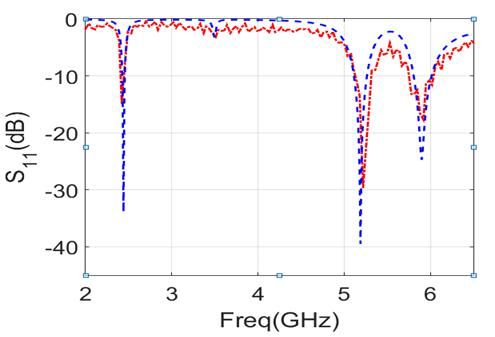

You can also read


