INSTALLATION AND MAINTANANCE MANUAL - PPL 2040 PROJECTOR LIFT - vogels-halterung.de
←
→
Page content transcription
If your browser does not render page correctly, please read the page content below
INSTALLATION AND
                        MAINTANANCE MANUAL
                                               PROJECTOR LIFT
                                                     PPL 2040
RELEASE ER 2020_02_21

                                          This document is property of Vogel’s Products BV.
                        Any distribution, reproduction, copying or publication of this document is prohibited.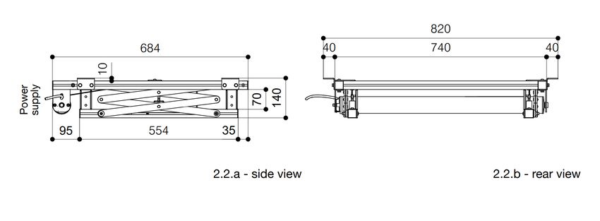
Installation and maintanance manual                                                              Projector lift PPL 2040

                                                                           INDEX

                                 In order to guarantee the best performances of your lift, please
                                           READ CAREFULLY this installation manual
                        1.0      GENERAL INFORMATION
                        1.1      Projector lift description
                        1.2      Manufacturer’s rights
                        1.3      Contents and map of this manual
                        1.4      Aim, contents and to whom it may concern this manual
                        1.5      Symbols legend
                        1.6      Technical assistance
                        1.7      Warranty – General information
                        1.8      Technical labels and markings used on the projector lift
                        1.9      Correct use of the projector lift
                        1.10     Improper use of the projector lift

                        2.0      GENERAL DESCRIPTION OF THE PROJECTOR LIFT
                        2.1      General description
                        2.2      Dimensions of closed projector lift
                        2.3      Dimensions of open projector lift
                        2.4      Mechanical specifications
                        2.5      Motor specifications

                        3.0      SAFETY STANDARDS AND RESIDUAL RISKS
                        3.1      Safety standards
                        3.2      Description of safety devices
                        3.3      Residual risks
                        3.4      Noise generated by the projector lift

                        4.0      INSTALLATION
                        4.1      Packaging contents
                        4.2      Installation “L” form metal ceiling mounting brackets
                        4.3      Ceiling mounting of the projector lift
                        4.4      Mounting of the videoprojector
                        4.5      Electrical connection
                        4.6      End-stops settings
                        4.7      Use of components for fixing the false ceiling tile

                        5.0      OUT OF ORDER
                        5.1      Waste of projector lift
RELEASE ER 2020_02_21

                                                           This document is property of Vogel’s Products BV.
                                         Any distribution, reproduction, copying or publication of this document is prohibited.
Installation and maintanance manual                                                              Projector lift PPL 2040

                        1.0      GENERAL INFORMATION

                        1.1     PROJECTOR LIFT DESCRIPTION
                        The projector lifts PPL 2040 is a motorzied lift for videoprojectors.
                        Therefore it can be included in the definition of machinery following the Directive
                        2006/42/CE and modifications.
                        The present installation manual, the conformity certification and the technical
                        labels on the lift are conform to this directive.

                        1.2    MANUFACTURER’S RIGHTS
                        Copyrights of this installation manual are exclusively of:

                                                           VOGEL’S PRODUCTS BV
                                                           Hondsruglaan 93
                                                           5628 DB Eindhoven
                                                           The Netherlands

                                                           Email: salesprof@vogels.com
                                                           www.vogels.com

                        1.3       CONTENTS AND MAP OF THIS MANUAL
                        This installation manual contains the description of “projector lift” as it is
                        manufactured by the manufacturer. This manual contains information about
                        installation, use and maintenance of the lift.
                        It also contains the information about the technical features and safe use of the
                        product.

                        The installation manual is composed from:

                        1.0      General information
                        2.0      Projector lift description
                        3.0      Safety and residual risks
                        4.0      Installation
                        5.0      Out of order
                        6.0      Check register
RELEASE ER 2020_02_21

                                                           This document is property of Vogel’s Products BV.
                                         Any distribution, reproduction, copying or publication of this document is prohibited.
Installation and maintanance manual Projector lift PPL 2040
1.4 AIM, CONTENTS AND TO WHOM IT MAY CONCERN
THIS MANUAL
This installation manual is addressed to:
-end user of the product, owner, people in charge of the product;
-people in charge of disintalling and moving;
-installers;
-users;
-maintanance technicians;
-people in charge for dismatling and wasting.
The information in this installation manual are aimed to indicate how to use the
lift and its technical features, how to move, install, set and use the lift.
Moreover, it contains the instructions for personnel that will be in charge for
maintenance and safety.
1.5 SYMBOLS LEGEND
In this installation manual, the following symbols will be used:
IMPORTANT
This symbol is used to indicate recommendations, rules and
information that every person has to take care during the life
cycle of the product (installation, use, maintenance, waste,
move).
DANGER
This symbol is used in the safety warnings of this installation
manual, in order to indicate behaviours that are absolutely
forbidden during the use of the lift, during maintenance
operations or when there are potential dangerous situations
that can cause serious injury or death.
WARNING
This symbol is used in the safety warnings of this installation
manual, in order to indicate dangerous situations that in case of
negligence, can cause limited injuries or damages. The symbol
can also be used to indicate situations that can damage the lift.
RELEASE ER 2020_02_21
This document is property of Vogel’s Products BV.
Any distribution, reproduction, copying or publication of this document is prohibited.Installation and maintanance manual Projector lift PPL 2040
1.6 TECHNICAL ASSISTANCE
Manufacturer’s customer service is available to support you with technical
information about:
-queries concerning this installation manual;
-supply of spare parts;
-maintenance procedures;
-severe repairing;
-possible malfunctions of the product.
In any case, it will be compulsory to quote serial number reported on the product
identification label n. 01 and reference page number of this installation manual.
1.7 WARRANTY – GENERAL INFORMATION
For warranty conditions, please refer to law in force within the country where the
product is used.
Please note the following issues:
1.7.1 Warranty includes substitution or repair of the faulty part (component or
part of the product) excluding installing, dismantling and transport costs of the
component or of the entire product.
1.7.2 The purchasing company is obliged to inform in written the manufacturer
about the fault within 8 days that the product run faulty. In case of negligence, the
warranty is voided.
In any case, the fault or complaint have to be verified by the manufacturer.
1.7.3 Warranty has duration of two years from end user’s purchasing date.
1.7.4 Any component or part of the product substituted under warranty is
manufacturer’s property only.
1.7.5 Warranty do not include:
-Damages caused by transport;
-Damaged parts subject to normal tear and wear due to weather and
environment conditions;
-Parts damaged due to insufficient, wrong or non-made maintenance;
-Parts damaged due to misuse, poor, wrong or non-authorized use;
-Parts damaged due to product modification, non-authorized repairing or
tampering;
-Parts damaged due to maintenance for alleged faults.
RELEASE ER 2020_02_21
This document is property of Vogel’s Products BV.
Any distribution, reproduction, copying or publication of this document is prohibited.Installation and maintanance manual Projector lift PPL 2040
1.7.6 Warranty is officially voided in case of:
- Repairing, modifications or components’ removing and substitution
not previously agreed and authorized by the manufacturer.
- Improper use from the end user.
- Lack of checking of the projector lift following the check register on
chapter 6.0
For these reasons, we suggest to inform promptly the manufacturer in case of
malfunctions or faults of the lift.
1.7.7 The actual installation manual with all its attachments represents the
official and only documentation of this product and it has to be archived and used
during the entire lifetime of the product.
1.7.8 In case the lift is passed to a third party, it is COMPULSORY that the
user hands over to the third party this document and to inform the manufacturer
of full name and address of the new owner.
1.7.9 The manufacturer reserves the right to modify at any time all the technical
documentation and, consequently, the installation manual of the product without
obligation of notice to the end users.
1.7.10 This installation manual is exclusively property of the manufacturer.
Handling of this installation manual has to be authorized by the manufacturer.
It is forbidden to copy, reproducing even partially, drawings and documentation
included in this manual.
All violations are punishable by law and subject to compensation for damages
under the protection of commercial rights.
It is allowed to keep one copy only for archive purposes.
RELEASE ER 2020_02_21
This document is property of Vogel’s Products BV.
Any distribution, reproduction, copying or publication of this document is prohibited.Installation and maintanance manual Projector lift PPL 2040
1.8 PRODUCT IDENTIFICATION LABELS
This lift is identified by product identification labels that indicate its essential
technical specifications.
1.8.1 Product identification
label n. 01.
This label reports the following
information:
A) Type of lift
B) Model name of lift
C) Serial number
D) Year of manufacturing
E) Motor power
F) Operating Frequency
G) Phases
H) Power consumption
Position
Product
identification
label n. 01
RELEASE ER 2020_02_21
This document is property of Vogel’s Products BV.
Any distribution, reproduction, copying or publication of this document is prohibited.Installation and maintanance manual Projector lift PPL 2040
1.8.2 Warning label n. 01
This label reports the following information:
Near the lift scissors, there is danger of cutting and crushing while the lift is
operating.
Position
Warning label n. 01
RELEASE ER 2020_02_21
This document is property of Vogel’s Products BV.
Any distribution, reproduction, copying or publication of this document is prohibited.Installation and maintanance manual Projector lift PPL 2040
1.8.3 Warning label n. 02
This label reports the following information:
A) Maximum load allowed (projector + tile of the false ceiling)
READ THE INSTRUCTIONS
MAX LOAD _ KG
Position
Warning label n. 02
RELEASE ER 2020_02_21
This document is property of Vogel’s Products BV.
Any distribution, reproduction, copying or publication of this document is prohibited.Installation and maintanance manual Projector lift PPL 2040
1.9 CORRECT USE OF THE PROJECTOR LIFT
1.9.1 The product is a motorized lift for videoprojectors. It is developed to
be installed and used indoor only. After the ceiling installation of the lift and the
projector made by professional technicians only, the end user is only authorized
to operate the lift up and down.
The lift has to be used from qualified persons only.
With “Qualified persons” we mean people that are instructed and
trained by the technician of the installation company about the
use of the lift and eventual risks related. Specifically, the end
users have to be instructed that the use of this machine has to
be done conforming to the indications of this installation manual.
The lift has to be used specifically for what it is purposed, that it
is indicated inside the installation manual.
These obligations have to be fulfilled also from forwarders,
installers, maintenance technicians and people in charge for
waste of the product, each of them regarding their own task.
1.10 IMPROPER USE OF THE PROJECTOR LIFT
The lift has been developed for the professional use mentioned
above, any other use can cause damages to the product and/or
create dangerous situations of which the manufacturer cannot be
considered responsible.
Specifically, it is forbidden to:
-Connect the lift to a different AC-power than the one specified
on the product identification label;
-Use the product to move up and down animals or objects
which are different from videoprojectors;
-Lift loads heavier than maximum load specified;
-Use the lift outdoor.
RELEASE ER 2020_02_21
This document is property of Vogel’s Products BV.
Any distribution, reproduction, copying or publication of this document is prohibited.Installation and maintanance manual Projector lift PPL 2040
2.0 GENERAL DESCRIPTION OF THE PROJECTOR
LIFT
2.1 GENERAL DESCRIPTION
The drawing here under points out the main components of the lift.
Left structural profile
30x30 (mm)
Fix pulley
Back structural profile
Ceiling mounting 30x30 (mm)
bracket Braided steel cable
40x40x60 (mm) covered with PVC Right structural
profile
30x30 (mm)
Closing plug
for profile Motor roller
30x30 (mm) tube
Front structural profile
30x30 (mm)
Bracket motor
roller tube
Left stabilizing
scissors
Right stabilizing
scissors
Left structural
profile
30x30 (mm)
Bracket for
fixing
the projector
Safety screw
Cable regulator
Right structural profile
RELEASE ER 2020_02_21
30x30 (mm)
Brass guide shoe
This document is property of Vogel’s Products BV.
Any distribution, reproduction, copying or publication of this document is prohibited.Installation and maintanance manual Projector lift PPL 2040
2.2 DIMENSIONS OF CLOSED PROJECTOR LIFT
The drawings here under 2.2.a - 2.2.b indicates maximum dimensions of the
closed lift.
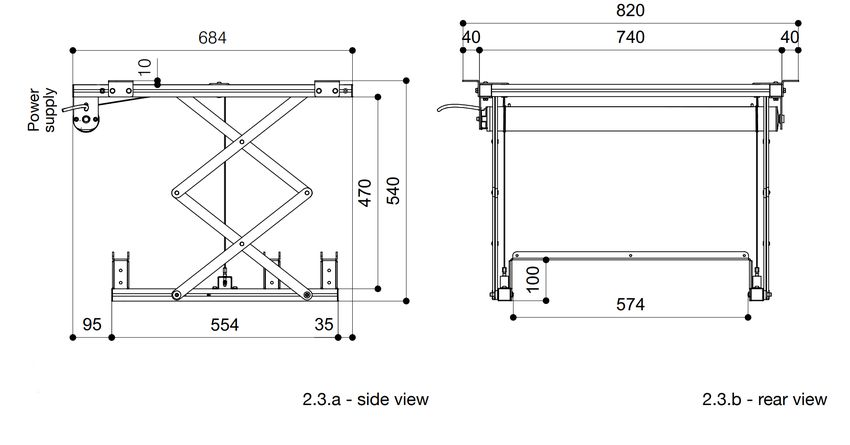
2.3 MECHANICAL SPECIFICATIONS
The drawings here under 2.3.a - 2.3.b indicate maximum dimensions of the open
lift.
RELEASE ER 2020_02_21
This document is property of Vogel’s Products BV.
Any distribution, reproduction, copying or publication of this document is prohibited.Installation and maintanance manual Projector lift PPL 2040
2.4 TECHNICAL SPECIFICATIONS
DIMENSION LIFT CLOSED 684x140x740 (WxHxD)
DIMENSION LIFT OPENED 680x540x740 (WxHxD)
MAXIMUM SIZE FIXING POINTS OF PROJECTOR 520x520 (WxD)
MAXIMUM PROJECTOR DIMENSIONS 570x590 (WxD)
MAXIMUM CAPACITY 30 Kg
NET WEIGHT OF THE PROJECTOR LIFT 13 Kg
2.5 MOTOR SPECIFICATIONS
GAPOSA MOTOR series XQ50P cod: cod:
Tubular motor with mechanical end stops XQ5P2017 XQ5P2016
POWER SUPPLY (V) 230 120
FREQUENCY (Hz) 50 60
LENGTH OF POWER CABLE 2.5 m 2.5 mt/8 ft
SECTION OF POWER CABLE WIRE 4x0.75 mm2 4x0.75 mm2
OPERATING TEMPERATURE -10°C/40°C 14°F/104°F
THERMO-PROTECTION 4 min -
PROTECTION (IP) 44 44
TORQUE (Nm) 20 20
SPEED (round/min) 17 16
MAXIMUM CONSUMPTION (W) 184 -
ABSORPTION (A) 0,80 1,10
RELEASE ER 2020_02_21
MAXIMUM ROTATIONS OF THE MOTOR 28 28
DUTY RATING 1minON/1minOFF
This document is property of Vogel’s Products BV.
Any distribution, reproduction, copying or publication of this document is prohibited.Installation and maintanance manual Projector lift PPL 2040
3.0 SAFETY STANDARDS AND RESIDUAL RISKS
3.1 SAFETY STANDARDS
-The lift has to be used specifically for what it is purposed. The manufacturer
cannot be held liable for eventual damages and injuries to people, animals and
objects in case of improper or wrong use of the lift itself. (see chapter 1.9).
DISCONNECT THE MAINS FROM THE LIFT
BEFORE STARTING ANY MAINTENANCE OR
CLEANING OPERATION OF THE PRODUCT.
CHECK CAREFULLY THAT THE LIFT IS
DISCONNECTED BEFORE ANY OPERATION.
-Do not disassemble any safety device mounted on the product (see chapter
3.2).
-Do not activate the lift if any safety device is dismantled or not properly fixed.
-It is possible to interrupt any operation of the lift, by releasing the button of the
supplied up/down switcher.
-In case of failure or malfunction of the lift, do not
attempt to carry out repairs. For any repairing, please
contact an authorised dealer which is authorised by
the manufacturer.
-Take care to do the electric connections as described in chapter 4.5.
-Take care to carry out maintenance program.
-Do not remove or alter product identification labels affixed on the lift by the
manufacturer.
RELEASE ER 2020_02_21
This document is property of Vogel’s Products BV.
Any distribution, reproduction, copying or publication of this document is prohibited.Installation and maintanance manual Projector lift PPL 2040
3.2 DESCRIPTION OF SAFETY DEVICES
The lift is equipped with two safety
screws fixed one onto the bottom left
profile and one onto the bottom right
profile.
The safety screws are fixed in a
specific position so that, in case one or
both steel cables break, the stabilizing
scissors will stop at the adjusted end
stop.
WARNING:
After having set the bottom end
stop, FIX TIGHTLY WITH PROPER
ALLEN KEY both safety screws
at a distance of 10 mm. from the
brass skater.
RELEASE ER 2020_02_21
This document is property of Vogel’s Products BV.
Any distribution, reproduction, copying or publication of this document is prohibited.Installation and maintanance manual Projector lift PPL 2040
3.3 RESIDUAL RISKS (rs)
3.3.1 During the use of the lift, please take care of areas that have residual risks
for people or objects, in case of incorrect use or evaluation error or inattention
eluding the norms specified in this installation manual and indications on product
identification labels.
The drawing here under identifies the residual risk area above the plate for fixing
the projector.
CEILING
Projector Projector
L=1,00 ml L=1,00 ml
Minimum height H= 2,50 ml without ceiling tile holder
Minimum height H= 2,75 ml with ceiling tile holder
rs
RELEASE ER 2020_02_21
FLOOR
This document is property of Vogel’s Products BV.
Any distribution, reproduction, copying or publication of this document is prohibited.Installation and maintanance manual Projector lift PPL 2040
3.3.2 Other residual risks
-Do not lift up or down people or animals.
-On the lift have to be installed videoprojectors only.
-Do not mount more load under the lift than the maximum load specified on the
warning label n. 02 (see 1.8.3).
-Do not leave free flying cables near the stabilizing scissors in order to avoid
cutting or damages on them.
3.3.3 Electrical risks
The lift has been developed according to the safety norms of industrial machines.
In any case, all specifications mentioned inside this installation manual and all
normal cautions have to be followed when using appliances connected to the
mains.
ANY OPERATION THAT INVOLVES PARTS CONNECTED TO THE MAINS
AND AT ELECTRICAL COMPONENTS HAVE TO BE CARRIED OUT FROM
QUALIFIED PERSONNEL ONLY, ALWAYS FOLLOWING THE PROCEDURE
HERE UNDER:
1) SWITCH OFF THE MACHINE.
2) DISCONNECT THE MAINS BY THE GENERAL SWITCH.
3) DISCONNECT THE LIFT FROM THE MAINS.
4) MAKE THE NECESSARY MAINTENANCE OPERATIONS.
3.4 NOISE GENERATED BY THE PROJECTOR LIFT
3.4.1 Warnings
The indicated noise values are indication levels and are not
necessarily safe operational levels.
Even though there is a relationship between emission
levels and exposure levels, this cannot be reliable in order
to define if there is need of supplementary precautions.
The factors that define the user’s exposure level include
the duration of exposure, the features of the room where
the lift is installed and other sources of noise.
The maximum exposure levels may vary between countries.
All these information will allow the user to better evaluate
danger and risk using this product.
The noise of the projector lift is LESS than 70 dBa.
RELEASE ER 2020_02_21
This document is property of Vogel’s Products BV.
Any distribution, reproduction, copying or publication of this document is prohibited.Installation and maintanance manual Projector lift PPL 2040
User has to pay attention also to other factors that can
influence the noise level of the product. Among the others,
two of these factors are: correct installation and careful
maintenance of the lift.
In case of continuous unusual noises and vibrations, the lift is probably damaged.
In this case, do not use the lift and proceed with an accurate and complete
maintenance.
RELEASE ER 2020_02_21
This document is property of Vogel’s Products BV.
Any distribution, reproduction, copying or publication of this document is prohibited.Installation and maintanance manual Projector lift PPL 2040
4.0 INSTALLATION
4.1 PACKAGING CONTENTS
When you open the packaging, please CHECK that it contains ALL the
components below. In case one or more components are missing, please refer
to the dealer you purchased the product from.
COMPONENTS OF THE
PACKAGING CARTON BOX
Box
lid
Polystyrene
sheet
Projector
lift
pcs. 01
Packaging carton box
Polystyrene
edges
Box
bottom
PLEASE
STORE UP
THE ORIGINAL
CARTON BOX
RELEASE ER 2020_02_21
This document is property of Vogel’s Products BV.
Any distribution, reproduction, copying or publication of this document is prohibited.Installation and maintanance manual Projector lift PPL 2040
pcs. 01
Small carton box containing all accessories
listed here under
fig.B fig.C fig.I
pcs. 04 pcs. 01 pcs. 01
“L” form metal brackets for Up/down switcher Installation and maintenance
ceiling mounting with 8 screws manual
and 8 washers
fig.D fig.E fig.F
pcs. 04 pcs. 04 pcs. 12
Sliding brackets to support the Threaded bars M6x25 cm – for Nuts M6 for mounting the
false ceiling plate fixing the ceiling cover plate threaded bars to the sliding
brackets
fig.L1 fig.L2 fig.M fig.N fig.O
pcs. 4 pcs. 4 pz. 5 pz. 1
RELEASE ER 2020_02_21
Blind screws M6 ø8 (L1) Hex head screws M6x10 Wire clamp Spiral for power
Bushes M6 ø10 (L2) cables
L=50 cm
This document is property of Vogel’s Products BV.
Any distribution, reproduction, copying or publication of this document is prohibited.Installation and maintanance manual Projector lift PPL 2040
4.2 INSTALLATION “L” FORM METAL CEILING
MOUNTING BRACKETS
Use the screws and washers to mount the “L” form metal brackets to the left and
right profile of the lift, as shown below.
Till the lift is not ceiling mounted,
do NOT remove the panels from
the lift structure in order to keep
tension onto the steel cables.
Inside each upper right and left structural pro-
file, there are four nuts to screw the screws to
the “L” form metal brackets.
The drawing below indicates the recommended position where to mount the “L”
form metal brackets. In this installation manual, we suppose an installation to a
flat and horizontal ceiling made of concrete.
RELEASE ER 2020_02_21
This document is property of Vogel’s Products BV.
Any distribution, reproduction, copying or publication of this document is prohibited.Installation and maintanance manual Projector lift PPL 2040
4.3 CEILING MOUNTING OF THE PROJECTOR LIFT
INSTALLATION OF THIS LIFT HAS TO BE
CARRIED OUT FROM AT LEAST TWO QUALIFIED
PERSONS.
Before proceeding with the ceiling mounting, we advice to mark the fixing points
where to fix the ceiling mounting brackets in the most accurate way.
The ceiling has to be clean and flat.
Installing the lift perfectly level is IMPORTANT and ensures silent movement
of the lift without any shaking, jolting or friction that would compromise the
alignment between projector and projection screen.
Measure centre hole of the brackets as accurate as possible.
Mark these measures onto the ceiling, in the required position, taking care to
keep the squareness between the four points.
RELEASE ER 2020_02_21
Now drill the holes in the ceiling in order to fix the brackets.
This document is property of Vogel’s Products BV.
Any distribution, reproduction, copying or publication of this document is prohibited.Installation and maintanance manual Projector lift PPL 2040
Without removing the panels from the lift structure (in order to keep tension onto
the steel cables), lift up the lift (using proper safety devices) aligning the brackets
with the drilled holes. Mount the lift to the ceiling using the suitable bolts/screws
and wall plugs (NOT SUPPLIED) suitable for the kind of ceiling and the weight
that have to be supported (max ø8).
After having fixed the lift to the ceiling, please remove the panels from the lift
structure.
Remove
adesive tape
RELEASE ER 2020_02_21
Remove
adesive tape
This document is property of Vogel’s Products BV.
Any distribution, reproduction, copying or publication of this document is prohibited.Installation and maintanance manual Projector lift PPL 2040
4.4 MOUNTING OF THE VIDEOPROJECTOR
Connect the projector lift to the mains as explained in chapter 4.5 and lower
the plate for fixing the projector to the desired height in order to fix the video-
projector with suitable screws (not supplied).
Please take care that the projector’s
centre of gravity is located in the
middle of the plate.
In order to define the ideal position of
the projector, please use a sprit level.
All the power and signal cables have
to be stored inside the plastic spiral.
WARNING: Use flexible cable only.
Cables that cannot be properly
bended are not allowed.
Insert and fix the cables only when
RELEASE ER 2020_02_21
the lift is completely in open position.
This document is property of Vogel’s Products BV.
Any distribution, reproduction, copying or publication of this document is prohibited.Installation and maintanance manual Projector lift PPL 2040
IT IS ABSOLUTELY FORBIDDEN
TO POSITION THE POWER CABLE
OF THE LIFT IN THE RESIDUAL
RISK AREA OF THE LIFT AS
SHOWN IN THE DRAWING HERE
AT THE RIGHT SIDE. OTHERWISE
THE CABLE CAN BE CUT DURING
OPERATION OF THE LIFT.
MOTOR AND
Motor power PROJECTOR CABLES
cable DO NOT HAVE
Projector power and INTERFERE NEITHER
signal cable inside WITH MOTOR TUBE
cable management NOR WITH STEEL
system. CABLES COVERED
WITH PVC.
RELEASE ER 2020_02_21
This document is property of Vogel’s Products BV.
Any distribution, reproduction, copying or publication of this document is prohibited.Installation and maintanance manual Projector lift PPL 2040
4.5 ELECTRICAL CONNECTION
4.5.1 Parts of the up/down switcher
1
included in the box
Fixing screws
for upper tile
to the bottom tile
2
Bottom tile
of the
switcher
Upper tile
with electric fruit
Up/down
switch buttons
Fig. 1 Without using screwdrivers, remove the up/down buttons.
Fig. 2 Turn the upper tile of the switcher in order to remove it
from the bottom tile.
The up/down switcher supplied gives the possibility to be fixed to the wall in two
different ways: with the bottom tile (A) or without the bottom tile (B).
A
RELEASE ER 2020_02_21
B
This document is property of Vogel’s Products BV.
Any distribution, reproduction, copying or publication of this document is prohibited.Installation and maintanance manual Projector lift PPL 2040
4.5.2 Use power cable with appropriate section for the motor power. The cable
has to be protected from high temperatures, oils, collisions, crushes and sharp
edges. Check that the mains tension is the same as the one indicated on the
product identification label n. 01 (see 1.8.1).
It is compulsory to connect the electrical connection of the lift also to earth.
4.5.3 Before connecting the lift to the mains, please carefully check the
security safety devices efficiency and the absence of failures or damages.
4.5.4 Please find here under the electrical connection diagram to be used
together with the supplied up/down switcher (see pag. 20 – Fig. C)
1 2 3
230v -> Blu Marrone Nero Giallo/Verde
Blue Brown Black Yellow/Green
120v -> Bianco Rosso Nero Verde
White Red Black Green
2 3
2
L 21281
1368
CEBEC
NF
DVE
1
K
EMA
EUR
10A / 250
2 3x1,5 mm2
4.5.5 Any operation that will involve electrical components has to be carried
out by qualified personnel only, always following the procedure here under:
1) SWITCH OFF THE MACHINE.
2) DISCONNECT THE MAINS BY THE GENERAL SWITCH.
3) DISCONNECT THE LIFT FROM THE MAINS.
RELEASE ER 2020_02_21
4) MAKE THE NECESSARY MAINTENANCE OPERATIONS
This document is property of Vogel’s Products BV.
Any distribution, reproduction, copying or publication of this document is prohibited.Installation and maintanance manual Projector lift PPL 2040
4.6 END-STOPS SETTINGS
4.6.1 In order to fix the “UPPER WARNING: in case the installer needs
END POSITION” to modify this end-stop, it is allowed to
lower the closed stop position. Do not
try to high the upper end-stop because
this will cause severe damages to the
product and invalidate warranty on the
lift.
Turn the screw on the motor shown on
the picture, clockwise to lower the lift.
4.6.2 n order to fix the “LOWER Turn the screw on the motor, as
END STOP POSITION” shown on the picture, anticlockwise
to increase the bottom stop point and
clockwise to reduce it.
RELEASE ER 2020_02_21
This document is property of Vogel’s Products BV.
Any distribution, reproduction, copying or publication of this document is prohibited.Installation and maintanance manual Projector lift PPL 2040
4.7 USE OF COMPONENTS FOR FIXING THE FALSE
CEILING TILE
4.7.1 The supplied components allow to install the lift inside a false ceiling.
THE FALSE CEILING PLATE IS NOT SUPPLIED
WITH THE LIFT.
THE MAXIMUM WEIGHT OF THE FALSE CEILING
PLATE HAS NOT TO EXCEED 2 KG.
Components to fix the false ceiling plate are listed in chapter 4.1 – Fig. D, E, F,
L1 and L2.
These components are suitable to fix a false ceiling plate under the projector in
order to hide the lift inside a false ceiling.
RELEASE ER 2020_02_21
This document is property of Vogel’s Products BV.
Any distribution, reproduction, copying or publication of this document is prohibited.Installation and maintanance manual Projector lift PPL 2040
4.7.2 Mounting
The following drawings explain how to mount the components above mentioned.
02 01
03
03
Inside the right and left lower
structural profile, there are
04
two nuts to be used to screw
the screws (Fig. 02) in order
to use the sliding brackets
(Fig. 01)
fig.01 Sliding brackets to fig.04 Threaded bars
support the false M6x25cm
ceiling plate
fig.02 Hex head screws fig.05 Blind screws
M6x10 M6x10
fig.03 Nuts M6 fig.06 Bushes
M6
RELEASE ER 2020_02_21
This document is property of Vogel’s Products BV.
Any distribution, reproduction, copying or publication of this document is prohibited.Installation and maintanance manual Projector lift PPL 2040
The sliding brackets (fig. 01) have to be positioned in the suitable point in order
to fix correctly the false ceiling plate.
After fixing the threaded bars (fig. 04) and defined the right length, the false ceil-
ing plate can be mounted using two types of screws.
VISIBLE SCREW NON VISIBLE SCREW
Drill the hole in the plate, fit in the Drill a partial hole at the top side of
bush from the bottom side and the plate and screw the blind screw
screw the threaded bar to it. into it avoiding to go through the
04 04
05
06
RELEASE ER 2020_02_21
This document is property of Vogel’s Products BV.
Any distribution, reproduction, copying or publication of this document is prohibited.Installation and maintanance manual Projector lift PPL 2040
5.0 OUT OF ORDER
At the end of the life of the lift, it has to be waste.
Please follow the procedure below.
If the machine has to be stored before wasting, please make the following
operations:
- Disconnect it from the mains;
- Put the lift in the original box;
- Put on the machine the following note:
“CAUTION: DO NOT USE THIS MACHINE
PRODUCT TO BE WASTED”
5.1 WASTE OF PROJECTOR LIFT
Before starting waste of the projector lift, please check that it is disconnected
from the mains.
In case the lift is still connected, disconnected it from the mains.
When wasting it, it is necessary to divide the plastic parts from the electrical
components in order to waste them properly following the recycling norms.
As regards the mechanic parts of the lift, it is suggested to divide steel parts
from other metals or alloys parts so that they can be sent for a proper recycling
process.
Dismantling the lift, please pay attention to all heavy metal parts in order to avoid
crushing.
Wasting of the components have to be carried out according to the laws in force
in the country where the lift is installed.
In any case, EC Directives have to be respected:
-91/156/CEE waste
-91/689/CEE dangerous waste
-94/62/CE packaging and packaging waste
These procedures have to be followed in order to recycle and waste in the
best way all the components and to avoid dangers for health and environment,
specifically avoiding:
-dangers for water, air, soil, fauna and flora;
-noises and smells
-damages to landscape and to cultural places based on the norms in
force.
RELEASE ER 2020_02_21
This document is property of Vogel’s Products BV.
Any distribution, reproduction, copying or publication of this document is prohibited.Installation and maintanance manual Projector lift PPL 2040
6.0 REGISTRO
CHECK REGISTER
CONTROLLI/CHECK REGISTER
6.1- VERIFICA
6.1 HALF -SEMESTRALE
YEARLY CHECK / HALF - YEARLY CHECK
Half-yearly, the following checks have to be carried on:
-Check if rolling up and rolling down is working properly, without frictions or
decelerations.
-Every six months (estimated 300 cicles) grease the 4 brass guide shoe (see.
par. 2.1) using white grease PTFE (Wurth HHS grease or equivalent).
-Check with the end user that projector lift and projection screen (if this is the
configuration) operate in different times (not at the same time) and that while
the first one is operating, the other one is not in power (switcher has to be a
deadman switcher or domotic system that works with this logic).
-Check steel cables covered by black PVC – no steel wires have to be visible
outside the black PVC scabbard.
-Check of the ceiling fixing brackets of the projector lft.
-Check that the end stops are set properly, so that in the rolled down position
(projector lift completely open) it remains at least 3 turns of steel wire onto the
roller tube.
-Check that bolts on the bottom ends of the steel cables are tightly fixed.
-Check that screws that fix projector to the projector lift are tightly fixed.
-Check safety devices – see chapter 3.2.
RELEASE ER 2020_02_21
This document is property of Vogel’s Products BV.
Any distribution, reproduction, copying or publication of this document is prohibited.You can also read