Cascade attitude control of a quadcopter in presence of motor asymmetry
←
→
Page content transcription
If your browser does not render page correctly, please read the page content below
Preprints of the 3rd IFAC Conference on Advances in Proportional-                                                             WeAT3.4
Integral-Derivative Control, Ghent, Belgium, May 9-11, 2018

                             Cascade attitude control of a quadcopter in
                                  presence of motor asymmetry ?
                                         Brice J. Njinwoua ∗ Alain Vande Wouwer. ∗
                               ∗
                                   University of Mons - Control Department, 7000 Mons, Belgium.

              Abstract: The quadcopter is one of the most used unmanned aerial vehicles in both military and
              commercial in- and outdoor applications. In this study, the problem of UAV attitude control is
              investigated when there are discrepancies in the characteristics of the 4 actuators, i.e., electrical
              motors and propellers. To tackle this problem in a simple way, a cascade control strategy is
              proposed with a PD controller in the inner loop to achieve stabilization, and PI controller in
              the outer loop to ensure disturbance rejection. This way, the external disturbance created by
              the actuator asymmetry is compensated by the PI loop. The robustness of the control strategy
              is tested in simulation as well as in real-life tests on a 1-DOF test bed.

              Keywords: Unmanned Aerial Vehicles, PID control, Disturbance rejection.

                      1. INTRODUCTION                                     Kalman Filters (UKF) were also considered (Abas et al.,
                                                                          2013), but CF is usually the preferred solution because of
Unmanned Aerial Vehicles, known as UAVs, have known                       its simplicity and high efficiency (Chang-Siu et al., 2011).
a growing interest in the last decade. This increasing
                                                                          In several cases, control strategies such as PID are based
popularity is due to their low cost, simple construction,
                                                                          on several simplifying assumptions. One of those is to
manoeuvrability and stability (Abas et al., 2013). They
                                                                          assume that the actuators are identical. However, this is
are used in a vast array of applications, including military
                                                                          not always verified in practice, and can considerably affect
applications (rescue, border surveillance), industry and
                                                                          the controller performance. To take the uncertainties into
agriculture applications (pipe maintenance, field monitor-
                                                                          account, some researchers have designed advanced control
ing), movie production, logistics, and leisure. UAVs can
                                                                          strategies, such as switching MPC (Alexis et al., 2011),
be classified in two categories : aeroplane and multirotors.
                                                                          integral back-stepping control (Bouabdallah and Siegwart,
Multirotors have advantages in terms of manoeuvrability
                                                                          2007), adaptive PID control (Fatan et al., 2013), etc.
in limited space and better hovering operation (Barve and
Patel, 2014).                                                             In this work, a simple control strategy is proposed, that
                                                                          is easy to implement and fully functional on a basic 16
Different multirotor configurations are available, and in
                                                                          M Hz chip. This control strategy is a cascade control with
this study, a quadcopter (or quadrotor) is under consider-
                                                                          a PD controller in the inner loop to achieve stabilization,
ation. A quadcopter has 6 degrees of freedom(3 linear and
                                                                          and a PI control in the outer loop to achieve performance
3 angular positions) and is controlled by 4 motors.
                                                                          (disturbance rejection).
In this connection, the first research topics focused on dy-
                                                                          This paper is organized as follows : Section 2 presents the
namic modelling of the copter (Hoffmann et al., 2007) fol-
                                                                          dynamical model of the quadcopter and some experimental
lowed by the introduction of more complex aero-dynamical
                                                                          results allowing parameter calibration. In Section 3, the
effects (Huang et al., 2009). Several control strategies
                                                                          characteristics of the actuators are discussed and the
were then designed, starting from basic PID controllers
                                                                          cascade control structure is developed. The simulation and
(Dikmen et al., 2009; Bolandi et al., 2013), and proceeding
                                                                          experimental results are presented and discussed in Section
with LQR controllers (Bouabdallah et al., 2004), Feedback
                                                                          4. Conclusions are drawn in Section 5.
control based on the representation in quaternions (Fresk
and Nikolakopoulos, 2013), back-stepping control (Madani                                    2. DYNAMIC MODEL
and Benallegue, 2006; Bouabdallah and Siegwart, 2005),
H∞ control (Raffo et al., 2010), feedback linearisation
                                                                          2.1 Description
(Benallegue et al., 2006) and cascade control Achtelik et al.
(2011); Szafranski and Czyba (2011); Tesch et al. (2016).
                                                                          A quadcopter is a flying object carried by four parallel pro-
Since control strategies require measurements of the posi-
                                                                          pellers mounted on two pairs of counter rotating motors.
tion and the attitude of the copter, several techniques were
                                                                          It has six degrees of freedom in the inertial frame, with
also developed to estimate accurately this information.
                                                                          variables x, y, z, U, V, W (linear positions and velocities),
The estimators used for UAVs are Kalman filtering (KF)
                                                                          φ, θ, ψ, P, Q, R (angular positions and velocities) as shown
and the complementary filter (CF) (Martin and Salaün,
                                                                          on Fig. 1. The rotation around the x, y and z axis are
2010). Extended Kalman Filters (EKF) and Unscented
                                                                          respectively called Roll, P itch and Y aw.
? University  of   Mons,    Mons,           Belgium      (e-mail    :      The rotation of the propellers creates two effects: a thrust
Alain.Vandewouwer@umons.ac.be).                                           or lift force and a drag torque. By varying the motor speed,

© 2018 International Federation of Automatic Control                113
Preprints of the 3rd IFAC Conference on Advances in Proportional-
Integral-Derivative Control, Ghent, Belgium, May 9-11, 2018
ẍ = UH (sin ψ sin φ + cos ψ sin θ cos φ)/m
ÿ = UH (sin ψ sin θ cos φ − cos ψ sin φ)/m
z̈ = UH cos φ cos θ/m − g
φ̈ = Uφ /Ixx (4)
θ̈ = Uθ /Iyy
ψ̈ = Uψ /Izz
where Ixx , Iyy , Izz are the rotary inertia around x, y and z
and and m the total mass of the quadcopter, respectively.
The selected frame is the famous DJI F450 and the control
unit is a Arduino U N O running at 16M hz with a 8-bit
micro-controller. The Electronic Speed Controller (ESC) is
420 Lite 4S 20A, which controls the four DJI motors 2312
E 960KV. Experiments following the protocol described
in (Mustapha et al., 2014) were achieved to determine the
values of kt and kd . The inertia Ixx , Iyy and Izz were cal-
culated by representing the quadcopter by separate simple
components idealized with simple geometric shapes, such
Fig. 1. Quadcopter coordinate system.
as cylinders, flat plates and rectangular parallelepipeds, in
several motion types can be generated. To increase the order to enable the use of classic formulas. The resulting
pitch, the speeds of motor 3 and 1 have to be increased inertia around the copter axes were then determined using
and decreased, respectively (or vice versa to decrease the the parallel-axis theorem and summed to obtain the global
pitch). The roll can similarly be manipulated by acting contribution [(Jones, 1975)]. The parameters are listed in
on motors 2 and 4. For spinning around the z-axis in a Table 1.
given direction, the speed of the motors rotating in the Table 1. Copter parameters
chosen direction has to be increased, while the speed of the
Parameter Value Description
counter-rotating motors has to be decreased in opposite
m 1.15kg Total mass
direction. l 16cm Dist. center-motors
Ixx 127.5kg · cm2 Inertia abt x-axis
2.2 Dynamic modelling Iyy 127.5kg · cm2 Inertia abt y-axis
Izz 242.3kg · m2 Inertia abt z-axis
kt 8.2 × 10⁻⁵ N · s2 /rad2 Thrust factor
The lift force fi generated by the rotation of the propeller kd 1.52 × 10⁻⁷ N · m · s2 /rad2 Drag factor
i is calculated as (Barve and Patel, 2014):
fi = ρ(H)CT AR2 ωi2 ' kt ωi2 (1) 3. PROBLEM STATEMENT AND CONTROLLER
DESIGN
where CT is the thrust coefficient, ρ is the air density
(function of the elevation), A is the rotor disk area and The control objective is to set the attitude angles φ, θ
R is the blade radius. and ψ to stabilize the copter, despite discrepancies in the
motors characteristics and propellers geometry.
The drag torque τi is given by (Barve and Patel, 2014):
For the sake of simplicity, only the control design for the
τi = kd ωi2 (2) roll angle φ is described, but the same approach can be
applied for the pitch and yaw angles.
where kd is the drag coefficient of the propeller. Lemma 1. In case of actuators (rotor + propeller) asym-
The forces and torques acting on the copter can thus be metry, the thrust and drag coefficients can differ from
computed as : motor to motor. The resulting effect is a disturbance
proportional to the difference δkt in the coefficients of the
UH = kt (ω12 + ω22 + ω32 + ω42 ) considered actuators.
Uφ = lkt (ω22 − ω42 )
(3) Proof. Eq. (4) and (3) give :
Uθ = lkt (ω32 − ω12 )
Uψ = kd (ω12 − ω22 + ω32 − ω42 ) Ixx φ̈ = Uφ
(5)
= l(kt2 ω22 − kt4 ω42 )
where UH , Uφ , Uθ and Uψ are the control inputs repre-
sentative of the total trust, roll, pitch and yaw torque If we consider an equilibrium point, where ω2 = ω4 =
respectively and l the distance from the centre of the ω0 , and a small variation δω of the angular velocity, the
copter to the centre of the rotors. In this study, we consider linearised model is given by:
a hovering flight with small variations of the angles to Ixx
achieve copter stabilization, and a simplified linear model φ̈ = 2kt2 (ω0 + δω) − 2kt4 (ω0 − δω) (6)
l
can be considered to design the control strategy. The = 2ω0 (kt2 − kt4 ) + 2δω(kt2 + kt4 )
(simplified) dynamics can be derived using Newton second
law and a transformation matrix (Barve and Patel, 2014). If kt2 6= kt4 , there is a disturbance P = 2ω0 (kt2 − kt4 ).
114Preprints of the 3rd IFAC Conference on Advances in Proportional-
Integral-Derivative Control, Ghent, Belgium, May 9-11, 2018
Several experiments have been carried out to assess the disturbance is added before the tuning of the PI controller.
characteristics of the actuators. Since the motors are The discrete controllers have the following structure :
controlled with a servo signal, the speed is modified by 1 1 z−1
changing the duty cycle through the pulse length (1100 - CP ID = P + I · Ts +D (7)
z−1 Ts z
1900µs). The characteristics of actuator 2 and 4 are shown
in figure 2. The controllers were tuned using the Matlab PID Tool
Box to guarantee stability, robustness and fast dynamics
in closed-loop. The sampling period Ts was chosen to
compromise speed of reaction and computational load of
the micro-controller. The values are listed in table 2.
Table 2. Parameters of the controllers.
Controller P I D Ts
PD 2.95 - 2.6 4 ms
PI 1.8 3.75 - 4 ms
Actuator saturation has to be considered - the physical
limits of the ESC are 1100 − 1900µs - and an anti-reset
wind-up using Back-calculation scheme is added with a
tracking time constant Kb = 2.75 found experimentally
by following the guidelines described in [(Astrom, 2002)].
4. RESULTS AND DISCUSSIONS
Fig. 2. Motor characteristics. 4.1 Simulation results
Simulation tests of the roll control loop are achieved with
The open-loop system is represented in figure 3. the other loops open. Initial conditions of 0.1, -0.1 and 0
for the roll, pitch and yaw angles, respectively, are used
and the pulse length of the four motors is taken equal to
1500µs. The results with asymmetry (10%) and without
are presented in figures 5
Fig. 3. Open-loop system with disturbance.
To compensate the disturbance action, we need a con-
troller with an integrator before the disturbance.
A cascade control structure is proposed with a PD con-
troller in the inner loop for system stabilization, and a PI
controller in the outer loop for disturbance rejection.
Fig. 5. Time evolution of the roll angle with no asymmetry.
The results of the roll, pitch and yaw angles in the global
closed-loop system are shown in Fig. 9, 10 and 11 respec-
tively.
Fig. 4. Cascade control.
4.2 Discussions
Tuning of the controllers : The stabilizing loop is first At first, we look at the individual loops to avoid distur-
closed and the PD controller is tuned to guarantee quick bances created by coupling effects. As we can see in Fig. 5,
response with no steady state error when there is no the controller performs well when the actuators are exactly
disturbance. The second loop is then closed and the the same (no asymmetry). The overshoot is less than 5%
115Preprints of the 3rd IFAC Conference on Advances in Proportional-
Integral-Derivative Control, Ghent, Belgium, May 9-11, 2018
Fig. 9. Roll angle : closed-loop system.
Fig. 6. Time evolution of the input signal with no asym-
metry.
Fig. 10. Pitch angle.
Fig. 7. Time evolution of the roll angle with 10% asymme-
try.
Fig. 11. Yaw angle.
increases as well as the settling time, which is now at
around 7s for the first control objective (Fig. 7). At steady
state, the motor inputs are different enough to generated
Fig. 8. Time evolution of the input signal with 10% the same lift effect (Fig. 8). Once the equilibrium point is
asymmetry. reached, the tracking performances are similar to the case
without discrepancies (See Fig. 7 second control objective
and the settling time is about 1s. The control inputs (see at 20s).
Fig. 6) at steady state are the initial values (1500µs) as By closing all the control loops, the coupling action be-
there is no disturbance to compensate. tween the yaw, pitch and roll appears. This can be seen
When an asymmetry of 10% is considered, the overshoot as a second disturbance in addition to the deviations in
116Preprints of the 3rd IFAC Conference on Advances in Proportional-
Integral-Derivative Control, Ghent, Belgium, May 9-11, 2018
the drag and lift factors of each actuator. As the yaw 5. CONCLUSION
angle is less important than the roll and pitch angles for
stabilisation, the closed-loop dynamics is chosen slower Asymmetry in the actuators of UAVs is frequent, and
than the ones of the other loops (Fig. 11). The overshoot create external disturbances that need to be compensated
is about 10% and the settling time 5s with 5% asymmetry by feedback control. In this study, a simple control strategy
on the lift and drag factors. based on a PD controller in the inner loop and a PI
The controllers on the roll and pitch angles compensate controller in the outer loop is proposed and tested in
quickly (3s) the disturbance introduced by the set-point simulation and experiments. The present study assumes
change on the yaw angle (see Fig. 9 and 10 ). small deviations, and a simplified dynamic model. Future
work entails the study of larger moves and the effect of
4.3 Experimental results nonlinearities.
The control law was implemented on an Arduino Uno
clocked with a 8-bit 16M hz-micro-controller, with a sam- REFERENCES
pling time of 4ms. Attitude measurement was obtained
using a complementary filter combining data from the Abas, N., Legowo, A., Ibrahim, Z., Rahim, N., and Kassim,
accelerometer and the gyroscope of IMU 6050. A.M. (2013). Modeling and system identification using
extended kalman filter for a quadrotor system. In
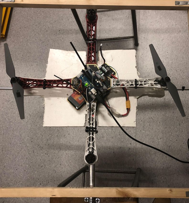
The copter was mounted on a 1-DOF bench test, as shown Applied Mechanics and Materials, volume 313, 976–981.
in Fig. 12 to control the roll angle. We assume that the Trans Tech Publ.
effect of the shaft’s inertia are small, thus can be neglected. Achtelik, M., Bierling, T., Wang, J., Hocht, L., and
Results are shown in Fig. 13. Holzapfel, F. (2011). Adaptive control of a quadcopter in
the presence of large/complete parameter uncertainties.
Infotech@ Aerospace, 29–31.
Alexis, K., Nikolakopoulos, G., and Tzes, A. (2011).
Switching model predictive attitude control for a
quadrotor helicopter subject to atmospheric distur-
bances. Control Engineering Practice, 19(10), 1195–
1207.
Astrom, K.J. (2002). Pid control. In Control System
Design, 216–251.
Barve, J. and Patel, K. (2014). Modelling, simulation
and altitude-range-analysis of quad-copter uav. IFAC
Proceedings Volumes, 47(1), 1126–1130.
Benallegue, A., Mokhtari, A., and Fridman, L. (2006).
Feedback linearization and high order sliding mode
observer for a quadrotor uav. In Variable Structure
Systems, 2006. VSS’06. International Workshop on,
365–372. IEEE.
Bolandi, H., Rezaei, M., Mohsenipour, R., Nemati, H.,
and Smailzadeh, S.M. (2013). Attitude control of a
quadrotor with optimized pid controller. Intelligent
Control and Automation, 4(03), 335.
Bouabdallah, S., Noth, A., and Siegwart, R. (2004). Pid vs
lq control techniques applied to an indoor micro quadro-
tor. In Intelligent Robots and Systems, 2004.(IROS
Fig. 12. The 1-DOF test platform. 2004). Proceedings. 2004 IEEE/RSJ International Con-
ference on, volume 3, 2451–2456. IEEE.
Bouabdallah, S. and Siegwart, R. (2005). Backstepping
and sliding-mode techniques applied to an indoor micro
quadrotor. In Robotics and Automation, 2005. ICRA
2005. Proceedings of the 2005 IEEE International Con-
ference on, 2247–2252. IEEE.
Bouabdallah, S. and Siegwart, R. (2007). Full control of
a quadrotor. In Intelligent robots and systems, 2007.
IROS 2007. IEEE/RSJ international conference on,
Fig. 13. Roll angle control. 153–158. Ieee.
Chang-Siu, E., Tomizuka, M., and Kong, K. (2011).
The controller performs well, although the bench creates Time-varying complementary filtering for attitude es-
an extra disturbance due to its geometrical asymmetry, timation. In Intelligent Robots and Systems (IROS),
its extra inertia and the recirculating airflow created by 2011 IEEE/RSJ International Conference on, 2474–
the propellers and the ground. The oscillations are due to 2480. IEEE.
the noisy measurements which can be attenuated using a Dikmen, I.C., Arisoy, A., and Temeltas, H. (2009). At-
Kalman filter. titude control of a quadrotor. In Recent Advances in
117Preprints of the 3rd IFAC Conference on Advances in Proportional-
Integral-Derivative Control, Ghent, Belgium, May 9-11, 2018
Space Technologies, 2009. RAST’09. 4th International
Conference on, 722–727. IEEE.
Fatan, M., Sefidgari, B.L., and Barenji, A.V. (2013).
An adaptive neuro pid for controlling the altitude of
quadcopter robot. In Methods and models in automation
and robotics (mmar), 2013 18th international conference
on, 662–665. IEEE.
Fresk, E. and Nikolakopoulos, G. (2013). Full quaternion
based attitude control for a quadrotor. In Control
Conference (ECC), 2013 European, 3864–3869. IEEE.
Hoffmann, G.M., Huang, H., Waslander, S.L., and Tom-
lin, C.J. (2007). Quadrotor helicopter flight dynamics
and control: Theory and experiment. In Proc. of the
AIAA Guidance, Navigation, and Control Conference,
volume 2, 4.
Huang, H., Hoffmann, G.M., Waslander, S.L., and Tomlin,
C.J. (2009). Aerodynamics and control of autonomous
quadrotor helicopters in aggressive maneuvering. In
Robotics and Automation, 2009. ICRA’09. IEEE Inter-
national Conference on, 3277–3282. IEEE.
Jones, R.M. (1975). Mechanics of composite materials,
volume 193. Scripta Book Company Washington, DC.
Madani, T. and Benallegue, A. (2006). Backstepping
control for a quadrotor helicopter. In Intelligent Robots
and Systems, 2006 IEEE/RSJ International Conference
on, 3255–3260. IEEE.
Martin, P. and Salaün, E. (2010). The true role of ac-
celerometer feedback in quadrotor control. In Robotics
and Automation (ICRA), 2010 IEEE International
Conference on, 1623–1629. IEEE.
Mustapha, Z., Saat, S., Husin, S., and Zaid, T. (2014).
Quadcopter physical parameter identification and alti-
tude system analysis. In Industrial Electronics & Appli-
cations (ISIEA), 2014 IEEE Symposium on, 130–135.
IEEE.
Raffo, G.V., Ortega, M.G., and Rubio, F.R. (2010). An
integral predictive/nonlinear h control structure for a
quadrotor helicopter. Automatica, 46(1), 29–39.
Szafranski, G. and Czyba, R. (2011). Different approaches
of pid control uav type quadrotor.
Tesch, D.A., Eckhard, D., and Guarienti, W.C. (2016).
Pitch and roll control of a quadcopter using cascade iter-
ative feedback tuning. IFAC-PapersOnLine, 49(30), 30 –
35. doi:https://doi.org/10.1016/j.ifacol.2016.11.118. 4th
IFAC Symposium on Telematics Applications TA 2016.
118You can also read