MarkerMouse: Mouse Cursor Control Using a Head-Mounted Marker
←
→
Page content transcription
If your browser does not render page correctly, please read the page content below
MarkerMouse: Mouse Cursor Control
                   Using a Head-Mounted Marker

                          Rados Javanovic and Ian Scott MacKenzie

                            Dept. of Computer Science and Engineering
                                        York Univeristy
                                Toronto Ontario Canada M3J 1P3
                              {rados,mack}@cse.yorku.ca

        Abstract. We propose MarkerMouse, an inexpensive method for controlling
        the mouse cursor using a web cam and a marker placed on the user’s forehead.
        Two modes of cursor control were compared: position-control and velocity-
        control. In position-control mode the cursor is positioned where the user's head
        is pointing. In velocity-control mode the mouse cursor moves in a constant
        speed in the direction the user’s head is pointing. In an experiment designed ac-
        cording to ISO 9241-9, we found a mean throughput 1.61 bps in position-
        control mode. Throughput was 34% less, or 1.07 bps, in velocity-control mode.
        We explain how from the marker image we control the mouse cursor position
        and reduce noise in our computations.

        Keywords: User interfaces, cursor control, web cam, marker tracking, head po-
        sition tracking, head-operated mouse, mouse emulation, ISO 9241-9.

1 Introduction
Interacting with desktop computers typically engages both hands of the user. This is
not a problem for most people, but for people with certain disabilities this scenario may
be untenable. Fortunately, there is considerable research on providing efficient access
to computers for disabled users. Several interesting technologies and solutions have
emerged such as blink-based text entry [7] and voice-based mouse cursor control [4].
   People with severe disabilities who cannot use, or have limited use of, their hands
and who cannot speak might not be able to control an on-screen cursor. Sometimes
the only option is to use the motion of the head to control the cursor. However, com-
mercial solutions are typically expensive. Origin Instruments’ HeadMouse Extreme,
for example, costs about one thousand U.S. dollars (http://www.orin.com). A solution
that costs less would be highly desirable. A new method for head cursor control is
proposed in this paper.
   Our proposed method does not require expensive hardware. It uses a common web
camera, a printout of a marker (Fig. 1a) mounted on the user’s forehead, and the soft-
ware to process the marker orientation and move the cursor. Notable, as well, is that
the user-to-computer interface is wireless, making it comfortable to use. We refer to
this head-mounted marker system for mouse cursor control as MarkerMouse.

K. Miesenberger et al. (Eds.): ICCHP 2010, Part II, LNCS 6180, pp. 49–56, 2010.
© Springer-Verlag Berlin Heidelberg 2010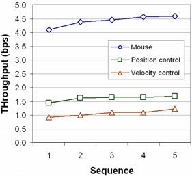
50 R. Javanovic and I.S. MacKenzie
(a) (b)
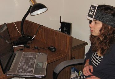
Fig. 1. MarkerMouse (a) printout (b) participant using MarkerMouse
The system is intended for people with restricted motor-control in the arms since
only head motion is required to move the mouse cursor. The rest of this paper is
organized as follows. In the next section, we review related work. Following this, we
describe our system and provide details on the interface and noise reduction algo-
rithm. Finally, we present an evaluation of our system, designed according to the
ISO 9241-9 standard for evaluating non-keyboard input devices [5].
2 Related Work
Most uses of head-mounted markers are in virtual worlds to connect the physical
position and movements of a real person with the virtual objects they interact with.
For example, Knoeflein et al. [6] used a head-mounted marker in a virtual world gam-
ing application. An IR marker was attached to a head-mounted camera and tracked to
determine the user’s head pose while playing ping-pong. Applications for cursor
control tend to use face and feature tracking, rather than makers [2, 11]. In these
applications, the focus is on the algorithms rather than the interaction. The use of a
head-mounted marker greatly simplifies the software, since the geometric features in
the marker are both precise and user-independent.
3 MarkerMouse
In this section, we describe the MarkerMouse interface, the position-control and ve-
locity-control modes of cursor control, button clicks, and noise reduction.
3.1 Interface Details
The MarkerMouse head-mounted marker system is simple to assemble. The user
simply prints the marker, positions it in some manner on her forehead, installs the
software, and performs a simple calibration procedure. The marker can be attached to
the user’s glasses, a hat, a bandana, or anything that might be comfortable.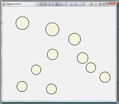
MarkerMouse: Mouse Cursor Control Using a Head-Mounted Marker        51

   For MarkerMouse to work, the user must sit in front of a web camera so that the
marker on the user's forehead is clearly visible (Fig. 1b). The orientation of the
marker with respect to the camera when the user is looking straight at the monitor is
the “neutral orientation”. The neutral orientation is sampled and used in computing
the movement of the marker and, hence, the motion of the mouse cursor.

3.2 Image Processing

The software linking the marker orientation to mouse cursor movement processes the
marker image as input by the web camera. The first task is to compute the marker’s
normal vector in 3D space. Since the marker has a distinct, non-symmetric pattern on
a square background it is possible to take an image captured by the web camera and
retrieve the 3D plane on which the marker is sitting. By finding this plane, we calcu-
late the normal vector of the marker. This is the neutral orientation. When the marker
undergoes movement, we take the angle between the new normal vector and the neu-
tral orientation and use this to determine where to move the cursor. To compute the
marker’s normal vector we used a software library called NyARToolkit1.

3.3 Button Clicks

Our primary focus is on emulating mouse cursor control, apart from the functionality
of clicking. To emulate a mouse button click, our system uses any key press on the
system’s keyboard. For accessible computing, depending on the disability, users may
have enough manual facility to press a switch, for example using their hand. For
users with severe disabilities who are not able to use their arms, the mouse button
clicks can be emulated in different ways, for example, using blinks [7, 10], intentional
muscle contractions [1, 3] or a sip-and-puff straw [12].

Position-Control and Velocity-Control
We evaluated two different modes of cursor control: position-control and velocity-
control. In position-control mode, the marker orientation on the user’s head deter-
mines the final position of the cursor on the screen. For example, if the user looks
straight at the monitor the cursor will be in the center of the screen. If the user looks
left the cursor will be on the left side of the screen, and if he then looks straight ahead
again the cursor will be in the center again. This is similar to the operation of a stylus
on a tablet or a finger on a touchscreen.
   In velocity-control mode, the head orientation determines the direction to move the
cursor. If the user looks straight at the monitor, the cursor is motionless. If the user
looks left the cursor starts moving left and continues moving left while the user con-
tinues to look left. Movement is initiated when the computed displacement is equiva-
lent to 200 pixels of mouse displacement. The rate of cursor movement is constant at
150 pixels per second. On the test system, this amounts to 10% horizontally and 16%
vertically of the display extent per second. In velocity-control mode, we constrained
the mouse movement to eight directions: up, down, left, right, and along the four
diagonals.

1
    Available from Virtual Worldlets (http://www.virtualworldlets.net/).
52 R. Javanovic and I.S. MacKenzie
3.4 Noise Reduction
Having the mouse cursor position directly dependent on the orientation of the marker
may cause the cursor to jump around due to camera noise and inaccuracies in comput-
ing the marker's transformation. We used two methods to minimize noise.
The first method uses dampening. Instead of using the marker's normal vector to
position the cursor directly, we compute the normal vector as a tentative cursor posi-
tion. For each step the cursor moves accordingly, but with added dampening, as
follows. Before the cursor is moved, a vector is computed in the direction of move-
ment. The length of the vector is the distance between the two positions. This vector
is multiplied by a dampening constant, D (0 < D < 1), and then the cursor takes a step
accordingly:
NewMousePos = MousePos + (TargetPos – MousePos) × D (1)
In our application, we set D to 0.5. For a large head movement, the cursor moves
relatively fast. For a small head movement, the cursor moves somewhat more slowly.
This helps reduce jitter in the cursor movement due to small variations in the compu-
tation of the marker's normal vector.
The second method uses a history of the mouse cursor position. Previous cursor
positions are recorded and used in computing the new position. Each new cursor
position was determined using the computed, new position averaged with the last 10
mouse positions. This sliding-average approach helps minimize big spikes in the
change of the marker's normal vector due to noise.
Applying these two methods together, the mouse cursor behaviour is more stable.
4 Method
While the design and initial testing of MarkerMouse system were promising, a proper
evaluation with a pool of participants is required to validate the design. Our experi-
mental evaluation tested how well participants could execute point-select tasks with
our MarkerMouse in each mode of cursor control. The evaluation also included a
generic mouse as a baseline condition.
Participants. Nine able-bodied participants were recruited from the local university
campus. Five were male, four female, Ages ranged from 22 to 27 years. All partici-
pants used a computer on a regular basis.
Apparatus (Hardware and Software). Participants worked on a Hewlett Packard
Pavilion dv7 laptop computer. The system includes an embedded web camera on the
top of the display. The resolution of the display was 1440 × 900 pixels. The operating
system was Microsoft Vista (Home Edition).
Two separate software utilities were used. For demonstrating MarkerMouse and to
provide participants the opportunity to practice, a simple program presenting an array
of circular targets was created. See Fig. 2a. The targets were of random diameters in
the range 30-80 pixels and were randomly scattered about the display. The targets
could be selected in any order. When a target was clicked on, the colour changed to
green to give visual feedback of a successful selection.MarkerMouse: Mouse Cursor Control Using a Head-Mounted Marker 53
(a) (b)
Fig. 2. Software (a) practice (b) ISO 9241-9 task #2
The experiment software was an implementation of task #2 in ISO 9241-9. See
Fig. 2b. Eight square targets were uniformly positioned around a layout circle with a
diameter of 600 pixels. Each target was 80 × 80 pixels. The participant first clicked on
the top target, then on the target directly opposite, then on the target next to the first
target, and so on around the layout circle. At any time, the target to select was high-
lighted. The target colour changed during selection. Selecting all targets was a “se-
quence”. This was repeated five times per mode of control.
Procedure. Participants sat in front of the laptop computer. The marker was put on
the participant’s forehead clearly visible to the web-cam. The participant was asked to
look straight into the screen and with a press of a button the current orientation of the
marker was saved. This orientation was the neutral orientation and was used for sys-
tem calibration. The calibration was done only once before each condition. Before
each condition, participants spent 10 minutes getting familiar with the head-mounted
marker using the practice software. For each condition, the participant was instructed
on how the mode of control worked and on what was expected. Testing started after
any button was pressed.
After the completion of all tests a questionnaire was handed to the participants to
solicit their impressions on the input modes. The questionnaire was based on response
items in ISO 9241-9 [5]. Each item had a rating from 1 to 5, as follows:
Smoothness during operation (1: very smooth – 5: very rough)
Mental effort required for operation 1: too low – 5: too high)
Accurate pointing (1: easy – 5: difficult)
Neck fatigue (1: none – 5: very high)
General comfort (1: very uncomfortable – 5: very comfortable)
Overall the input device was (1: very difficult to use – 5: very easy to use)
Experiment design. The experiment was a 3 × 5 within-subjects design, with the
following independent variables and levels:
Mode of control: Position-control, Velocity-control, Generic Mouse
Sequence: 1, 2, 3, 4, 5
Participants were divided into three groups with the mode of control conditions ad-
ministered using a Latin square.54 R. Javanovic and I.S. MacKenzie
The experiment included throughput as the dependent variable, as specified in
ISO 9241-9. Throughput, in bits per second (bps), is a composite measure combining
the speed and accuracy of participant responses. After each sequence of trials,
throughput was calculated using
Throughput = IDe / MT .(2)
MT is the mean movement time per trial over all trials in a sequence. IDe is the effec-
tive index of difficulty, computed as
IDe = log2(D / We + 1) (3)
where D is the distance in pixels between the two targets (600 pixels) and We is the
width of the distribution of clicks. We, is computed using
We = 4.133 × SDx (4)
where SDx is the standard deviation in selection coordinates along the axis of ap-
proach. Details are provided in other papers [e.g., 9].
5 Results and Discussion
Throughput. As clearly seen in Fig. 3a, there was a significant effect of mode of
control on throughput (F3,8 = 555.7, p < .0001). Not surprisingly, the mouse per-
formed best. Its throughput of 4.42 bps is consistent with mouse results in other
ISO 9241-9 evaluations [9], thus validating our methodology.
(a) (b)
Fig. 3. Throughput (a) by mode of control (b) by sequence
The mean throughput for position-control movement of 1.61 bps was about 34%
higher than the throughput of 1.07 bps observed for velocity-control movement.
While substantially less than the throughput for the mouse, these figures are consis-
tent with throughput for other pointing devices, such as a joystick (1.8 bps; see [8]).
As the trials continued, the throughput for both the position-control and velocity-
control modes improved (Fig. 3b). After the first sequence, the position-control mode
did not improve much, but the throughput for the velocity-control mode kept increasing.MarkerMouse: Mouse Cursor Control Using a Head-Mounted Marker 55
Position-control mode produced better results because the mouse cursor went to
the target position determined by the marker orientation almost instantaneously. In
velocity-control mode, the mouse cursor had a constant speed (150 pixels/second).
This slowed velocity-control mode, as multiple iterations of move and adjust were
needed to position the cursor on the target.
Participant feedback. As MarkerMouse is intended for accessible computing and
testing was done with able-bodied participants, there was an expected bias favoring
the mouse. In comparing the two modes of control for MarkerMouse, participants
indicated an overall preference for the position-control mode, rating it better than
velocity-control mode for both neck fatigue and accurate pointing. Participants, how-
ever, gave slightly better scores to velocity-control mode for mental effort and
smoothness.
6 Conclusions
In this paper we introduced a new method of controlling a mouse cursor using a
marker placed on the user's forehead. Two methods of cursor control, position-control
and velocity-control, were compared along with a desktop mouse. The mean through-
puts for the position- and velocity-control modes were 1.61 bps and 1.07 bps, respec-
tively, compared to the desktop mouse mean throughput of 4.42 bps.
Noise in marker detection was a limitation for the position-control mode. Velocity-
control mode was less influenced by noise. However, because velocity-control is less
intuitive, velocity-control mode performed worse than position-control mode.
An improvement for position-control movement would be a better way to deal with
the marker detection noise, to improve precision and reduce jitter. This problem can
be approached from two directions: to have a more robust method for marker detec-
tion and marker orientation calculation, and to have a better smoothing algorithm that
minimizes noise after the orientation was computed.
References
1. Barreto, A.B., Scargle, S.D., Adjouadi, M.: A practical EMG-based human-computer inter-
face for users with motor disabilities. Journal of Rehabilitation Research 37, 53 (2000)
2. Chauhan, V., Morris, T.: Face and feature tracking for cursor control. In: Proceedings of
the Scandinavian Conference on Image Analysis (Unpublished, 2001); retrieved from
http://www.cs.man.ac.uk/~tmorris/SCIA630.pdf (December 23, 2009)
3. Felzer, T., Nordmann, R., Rinderknecht, S.: Scanning-based human-computer interaction
using intentional muscle contractions. In: Smith, M.J., Salvendy, G. (eds.) Universal Ac-
cess in Human-Computer Interaction, Part II, HCII 2009. LNCS, vol. 5618, pp. 309–318.
Springer, Heidelberg (2009)
4. Harada, S., Landay, J.A., Malkin, J., Li, X., Bilmes, J.A.: The vocal joystick: Evaluation of
voice-based cursor control techniques. In: Proceedings of the ACM Conference on Com-
puters and Accessibility - ACCESS 2006, pp. 187–204. ACM, New York (2006)
5. ISO, Ergonomic requirements for office work with visual display terminals (VDTs) - Part
9: Requirements for non-keyboard input devices (ISO 9241-9), International Organisation
for Standardisation. Report Number ISO/TC 159/SC4/WG3 N147, February 15 (2000)56 R. Javanovic and I.S. MacKenzie
6. Knoerlein, B., Szekely, G., Harders, M.: Visuo-haptic collaborative augmented reality
ping-pong. In: Proceedings of the International Conference on Advances in Computer
Entertainment Technology - ACE 2007, pp. 91–94. ACM, New York (2007)
7. MacKenzie, I.S., Ashtiani, B.: BlinkWrite: Efficient text entry using eye blinks. In: Uni-
versal Access in the Information Society (UAIS) (in press)
8. MacKenzie, I.S., Kauppinen, T., Silfverberg, M.: Accuracy measures for evaluating com-
puter pointing devices. In: Proceedings of the ACM Conference on Human Factors in
Computing Systems - CHI 2001, pp. 119–126. ACM, New York (2001)
9. Soukoreff, R.W., MacKenzie, I.S.: Towards a standard for pointing device evaluation:
Perspectives on 27 years of Fitts’ law research in HCI. International Journal of Human-
Computer Studies 61, 751–789 (2004)
10. Su, N.M., Mark, G.: Communication chains and multitasking. In: Proceedings of the ACM
Conference on Human Factors in Computing Systems - CHI 2008, pp. 83–92. ACM, New
York (2008)
11. Tu, J., Tao, H., Huang, T.: Face as mouse through visual face tracking. Computer Vision
and Image Understanding 108, 35–40 (2007)
12. Yanco, H.A.: Wheelesley: A robotic wheelchair system: Indoor navigation and user inter-
face. In: Mittal, V.O., Yanco, H.A., Aronis, J., Simpson, R. (eds.) Assistive Technology
and Artificial Intelligence, pp. 256–268. Springer, Berlin (1998)You can also read