IMX RT1176 Developer's Kit User Guide - Get Up-and-Running Quickly and Start Developing Your Application On Day 1! - Embedded Artists
←
→
Page content transcription
If your browser does not render page correctly, please read the page content below
iMX RT1176 Developer’s Kit - User Guide
Copyright 2021 © Embedded Artists AB

                                       iMX RT1176 Developer’s Kit
                                              User Guide

                           Get Up-and-Running Quickly and
                           Start Developing Your Application On Day 1!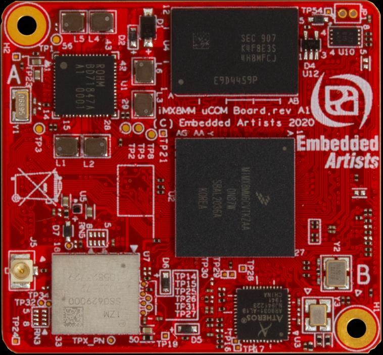
iMX RT1176 Developer’s Kit - User Guide                                                                            Page 2

                        Embedded Artists AB
                        Rundelsgatan 14
                        211 36 Malmö
                        Sweden
                        https://www.EmbeddedArtists.com

                        Copyright 2021 © Embedded Artists AB. All rights reserved.
                        No part of this publication may be reproduced, transmitted, transcribed, stored in a retrieval system, or
                        translated into any language or computer language, in any form or by any means, electronic,
                        mechanical, magnetic, optical, chemical, manual or otherwise, without the prior written permission of
                        Embedded Artists AB.

                        Disclaimer
                        Embedded Artists AB makes no representation or warranties with respect to the contents hereof and
                        specifically disclaim any implied warranties or merchantability or fitness for any particular purpose.
                        Information in this publication is subject to change without notice and does not represent a
                        commitment on the part of Embedded Artists AB.

                        Feedback
                        We appreciate any feedback you may have for improvements on this document. Please send your
                        comments to support@EmbeddedArtists.com.

                        Trademarks
                        All brand and product names mentioned herein are trademarks, services marks, registered
                        trademarks, or registered service marks of their respective owners and should be treated as such.

Copyright 2021 © Embedded Artists AB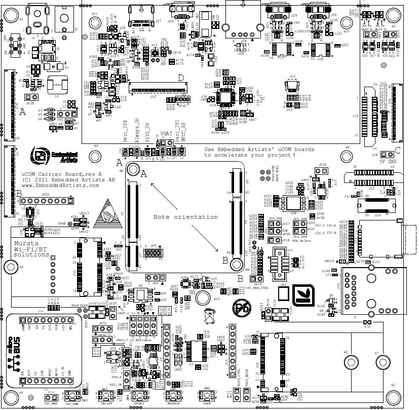
iMX RT1176 Developer’s Kit - User Guide                                                       Page 3

                                                  Table of Contents
                                                  1 Document Revision History                             4

                                                  2 Getting Started                                       5
                                                  2.1     iMX RT1176 Developer's Kit Content               5
                                                  2.2     Hardware Overview                                6
                                                  2.3     Connecting - Get Started                         7
                                                  2.3.1    Console                                         7
                                                  2.3.2    Tera Term Terminal Emulation Application        7
                                                  2.3.3    PuTTY terminal emulation application            9
                                                  2.3.4    Powering                                        9
                                                  2.3.5    Console output                                10
                                                  2.4     Alternative Powering                           10
                                                  2.5     ESD Precaution                                 10
                                                  2.6     Note uCOM Orientation when Mounting            11
                                                  2.7     General Handling Care                          12
                                                  2.8     OTP Fuse Programming                           12
                                                  2.9     CE Assessment                                  12

                                                  3 uCOM Carrier Board Design                            13

                                                  4 Disclaimers                                          14
                                                  4.1     Definition of Document Status                  15

Copyright 2021 © Embedded Artists AB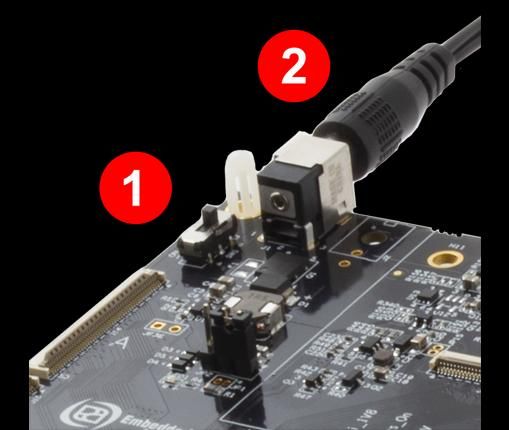
iMX RT1176 Developer’s Kit - User Guide                                                                  Page 4

                        1 Document Revision History
                        Revision       Date         Description
                        PA1            2021-03-08   Initial release.
                        PA2            2021-06-17   Minor layout corrections.
                        PA3            2021-09-20   Updated information about the uCOM Carrier Board hardware.

Copyright 2021 © Embedded Artists AB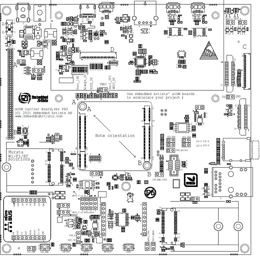
iMX RT1176 Developer’s Kit - User Guide Page 5
2 Getting Started
This chapter contains information about how to get acquainted with the iMX RT1176 Developer's Kit.
Please read this chapter first before you start using the board - it will be well spent time!
First of all, thank you for buying Embedded Artists’ iMX RT1176 Developer’s Kit based on NXP’s ARM
Cortex-M7/M4 i.MX RT1176 Crossover MCU. You will get up-and-running quickly!
Section 2.1 contains a list of what is included in the iMX RT1176 Developer's Kit.
Section 2.2 together with Figure 10 in chapter 3 gives an overview presentation of the
hardware and the interfaces and connectors available.
Section 2.3 describes how to connect the USB cable, install the UART-to-USB driver and
power-up the board the first time.
Section 2.4 presents an alternative powering solution via the USB console interfaces.
Section 2.5 - 2.9 describes important handling and care issues.
Chapter 3 presents the uCOM Carrier Board and where to find more information about the
hardware design of it.
To get started with program development and program download/flashing, see document iMX RT1176
Developer's Kit Program Development Guide.
2.1 iMX RT1176 Developer's Kit Content
One iMX RT1176 uCOM board mounted on one uCOM Carrier board, see Figure 1 below.
One 100/10Mbps Ethernet adapter with 40-pos flat cable
One MIPI-to-HDMI adapter
One 12V supply
One micro-B to A USB cable
One MCU-Link debug interface
For program development you can optionally use another debug probe (than MCU-Link), like ULINK, J-
LINK or LPC-Link2, and a program development environment, like MCUXpresso, Keil uVision or IAR
Embedded Workbench. For more information about program development, see document iMX RT1176
Developer's Kit Program Development Guide.
Copyright 2021 © Embedded Artists AB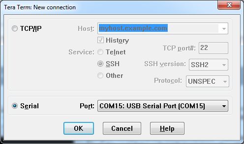
iMX RT1176 Developer’s Kit - User Guide                                                                            Page 6

                        2.2        Hardware Overview
                        Figure 1 below illustrates the top side of the uCOM Carrier board. Some key components, relevant to
                        get started, have been marked in the picture.

                                       2                        3                    4

                  1

                                           5                6
                        Figure 1 – iMX RT1176 Developer's Kit

                               1. ON/OFF switch (instead of having to plug in/out the 12V power supply barrel connector).
                               2. 12V power supply input, 12V/2-3A DC, via a 2.1mm power jack. The center position is the
                                  positive terminal.
                               3. USB OTG connector - this USB interface can, together with a PC application, be used to
                                  program the flash memory of the iMX RT1176 uCOM board.
                               4. UART-to-USB bridge - this gives access to the console UART of the i.MX RT1176 MCU.
                               5. ISP Enable push-button (and jumper, left of button) - pressing this button (or shorting jumper)
                                  while the board power up will place the i.MX RT1176 is ISP mode (typically used for
                                  programming the iMX RT1176 uCOM board flash memory).
                               6. Reset push-button - a press will generate a power cycle (in default behavior).

                        Figure 10 in chapter 3 gives a slightly more detailed presentation of all interfaces and connectors on
                        the board.

Copyright 2021 © Embedded Artists AB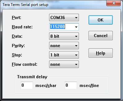
iMX RT1176 Developer’s Kit - User Guide                                                                             Page 7

                        2.3        Connecting - Get Started
                        It is recommended to visit the Getting Started with uCOM Developer's Kit landing page:
                             https://www.embeddedartists.com/getting-started-with-ucom-developers-kit/

                        2.3.1          Console
                        Begin by connecting the micro-B USB connector to position 1) in Figure 1 above. Connect the other
                        end of the USB cable to the PC.
                        Meanwhile the PC will typically install a driver automatically for the UART-to-USB bridge that creates a
                        Virtual COM port, if it is not already installed. If you have problems the drivers can be downloaded from
                        the links below:
                              http://www.ftdichip.com/Drivers/VCP.htm
                              http://www.ftdichip.com/Support/Documents/InstallGuides.htm
                        When the driver has been installed, a new COM port will listed under “Ports” in the Device Manager as
                        shown in Figure 2. Please note that the actual port number will most likely be different on your
                        computer.

                        Figure 2 – Virtual COM port shown in device manager

                        The next step is to open a terminal application and attached it to the Virtual COM port that has just
                        been created. The baud rate should be 115200.
                        Some development environments/IDEs have a built-in terminal application that can be used.
                        Sometimes it is better to have a terminal application with more features. For increased flexibility, we
                        recommend using any of the two alternative terminal applications presented in the following sub-
                        sections.

                        2.3.2          Tera Term Terminal Emulation Application
                        We recommend that you use Tera Term which can be downloaded and installed from either of the
                        links below.
                              https://ttssh2.osdn.jp/index.html.en
                              http://sourceforge.jp/projects/ttssh2/releases/
                        Launch Tera Term. The first time it launches, it will show you the following dialog. Select the serial
                        option. Assuming the USB cable is connected to the uCOM Carrier Board, there should be a COM port
                        automatically populated in the list.

Copyright 2021 © Embedded Artists AB
iMX RT1176 Developer’s Kit - User Guide Page 8
Figure 3 – Tera Term New Connection Window
Configure the serial port settings (using the COM port number identified earlier) to 115200 baud rate, 8
data bits, no parity and 1 stop bit. To do this, go to Setup Serial Port and change the settings.
Figure 4 – Tera Term Serial Port Setup
Verify that the connection is open. If connected, Tera Term will show something like below in its title
bar.
Figure 5 – Tera Term Menu
Copyright 2021 © Embedded Artists ABiMX RT1176 Developer’s Kit - User Guide Page 9
2.3.3 PuTTY terminal emulation application
Alternatively you can use PuTTY. It is another commonly used terminal emulation application. PuTTY
can be downloaded and installed from the link below.
http://www.chiark.greenend.org.uk/~sgtatham/putty/download.html
Launch PuTTY by either double clicking on the *.exe file you downloaded or from the Start menu,
depending on the type of download you selected.
In the window that launches, select the Serial radio button and enter the COM port number that you
determined earlier. Also enter the baud rate, in this case 115200.
Figure 6 – PuTTY New Session Configuration
Click Open to open the serial connection. Assuming the FTDI cable is connected and you entered the
correct COM port, the terminal window will open. If the configuration is not correct, PuTTY will alert
you.
2.3.4 Powering
The 12V power supply comes with plug adapters for different countries. Select the plug used in your
country and attach it to the power supply. Connect the 2.1mm male barrel jack to the uCOM Carrier
board (2 in the picture below).
Set the Power on/off switch (1 in the picture) to On state and the board will now power up.
Figure 7 – 12V Power Supply input
Copyright 2021 © Embedded Artists ABiMX RT1176 Developer’s Kit - User Guide Page 10
2.3.5 Console output
The pre-loaded demo application will output a greeting message on the console. Verify that you can
see this text in the terminal application.
2.4 Alternative Powering
The board is normally powered from the 12V input supply voltage. The board can also be powered via
the console USB interfaces, J29 and J30. Power selector JP2 must be placed in the 2-3 position for
this alternative supply source.
Note that this setup will not always work because the power consumption of the entire board can be
higher than what a PC/laptop can provide. This might also be true for a powered USB hub.
The 12V supply input is needed when running USB Host application that require powering external
USB devices.
See Figure 8 below where to locate JP2.
Powering Selector
JP2
Right (1-2): Power via 12V input supply, default
Left (2-3): Power from USB consoles (J29 and J30)
Figure 8 – Location of Powering Selector, JP2
2.5 ESD Precaution
Please note that the iMX RT1176 uCOM Board and uCOM Carrier Board come
without any case/box and all components are exposed for finger touches – and
therefore extra attention must be paid to ESD (electrostatic discharge)
precaution.
Make it a habit always to first touch the metal surface of one of the USB,
SD or Ethernet connectors for a few seconds with both hands before
touching any other parts of the boards. That way, you will have the same
potential as the board and therefore minimize the risk for ESD.
Never touch directly on the iMX RT1176 uCOM Board and in general as little as possible on the uCOM
Carrier Board. The push-buttons on the uCOM Carrier Board have grounded shields to minimize the
effect of ESD.
Note that Embedded Artists does not replace boards that have been damaged by ESD.
Copyright 2021 © Embedded Artists ABiMX RT1176 Developer’s Kit - User Guide Page 11
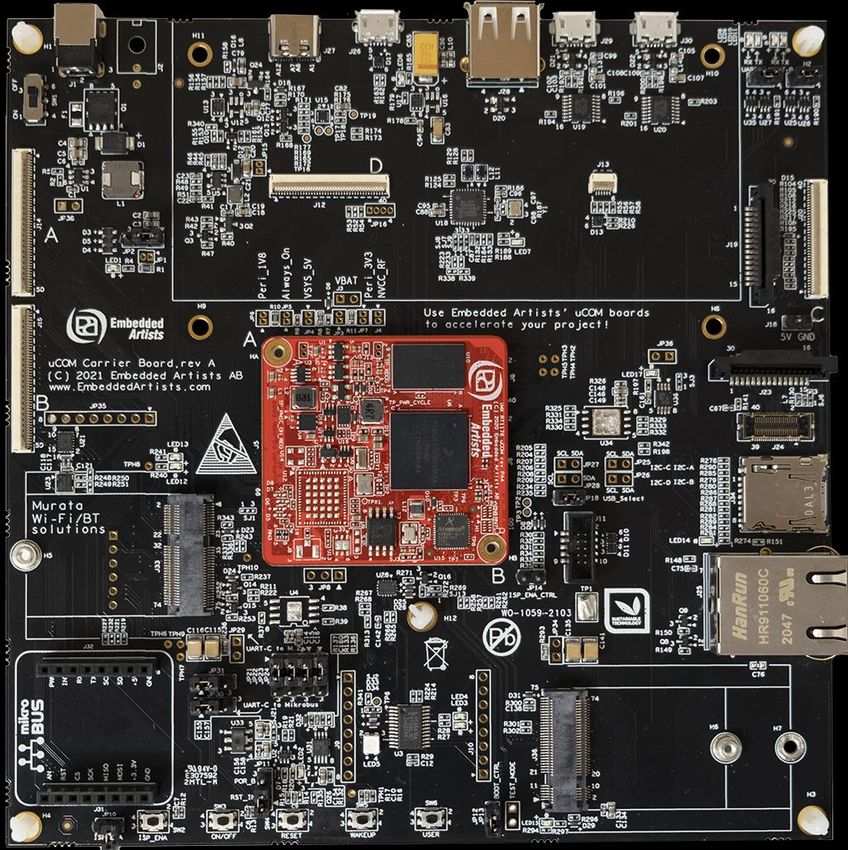
2.6 Note uCOM Orientation when Mounting
Normally, the iMX RT1176 uCOM board should never be removed/unmounted from the uCOM Carrier
Board. If it has been removed and it's time to mount it again, note that it is possible to mount the uCOM
board with incorrect orientation. Doing that will damage the uCOM board beyond repair and can also
damage the carrier board. The picture below illustrates how to identify the correct orientation of the
iMX RT1176 uCOM.
Always match the "A" and "B" marking on the uCOM with the "A" and "B" on the Carrier Board.
J8/JD
40-pos
J5/JA
100-pos
J6/JB
100-pos
J7/JC
40-pos
Note: match "A" on the EAuCOM
with "A" on the uCOM Carrier Board.
Figure 9 – Orientation of iMX RT1176 uCOM Board when Mounted on the uCOM Carrier Board
Copyright 2021 © Embedded Artists ABiMX RT1176 Developer’s Kit - User Guide Page 12
2.7 General Handling Care
Handle the iMX RT1176 uCOM Board and uCOM Carrier Board with care. The boards are not
mounted in a protective case/box and are not designed for rough physical handling. Connectors can
wear out after excessive use. The uCOM Carrier Board is designed for prototyping use, and not for
integration into an end-product.
Also handle the iMX RT1176 uCOM board with great mechanical care. Only remove/unmount it from
the uCOM Carrier board if absolutely needed. Only use small movements and small force. Do not
insert a screwdriver between the uCOM board and uCOM Carrier board and bend without having first
watched the Youtube clip we have published about this:
https://www.youtube.com/watch?v=UiYR1Oz8YPw, title "How to unmount the uCOM board from the
adapter"
2.8 OTP Fuse Programming
The i.MX RT1176 MCU has on-chip OTP fuses that can be programmed, see NXP documents
IMXRT1170RM, i.MX RT1170 Processor Reference Manual for details. Once programmed, there is no
possibility to reprogram them.
iMX RT1170 uCOM Boards are delivered with BT_FUSE_SEL = 1. No other OTP fuse has been
programmed. It is completely up to the COM board user to decide if OTP fuses shall be programmed
and in that case, which ones.
Just programming BT_FUSE_SEL = 1 will set the boot device to the on-board QSPI flash. It is possible
to specify another boot mode by programming the BOOT_CFG1[7:0] and BOOT_CFG2[3:0] fuses.
Note that Embedded Artists does not replace iMX RT1176 uCOM Boards because of wrong OTP
programming. It’s the user’s responsibility to be absolutely certain before OTP programming
and not to program the fuses by accident.
2.9 CE Assessment
The iMX RT1176 Developer's Kit (consisting of the iMX RT1176 uCOM Board and uCOM Carrier
Board) is CE marked. See separate CE Declaration of Conformity document.
The iMX RT1176 Developer's Kit is a class A product. In a domestic environment this product may
cause radio interference in which case the user may be required to take adequate measures.
EMC emission test has been performed on the iMX RT1176 Developer's Kit. Standard interfaces like
Ethernet, USB, serial have been in use. General expansion connectors where internal signals are
made available (for example processor pins) have been left unconnected. Connecting other devices to
the product via the general expansion connectors may alter EMC emission. It is the user’s
responsibility to make sure EMC emission limits are not exceeded when connecting other devices to
the general expansion connectors of the iMX RT1176 Developer's Kit.
Due to the nature of the iMX RT1176 Developer's Kit – an evaluation board not for integration into an
end-product – fast transient immunity tests and conducted radio-frequency immunity tests have not
been executed. Externally connected cables are assumed to be less than 3 meters. The general
expansion connectors where internal signals are made available do not have any other ESD protection
than from the chip themselves. Observe ESD precaution.
Note that the iMX RT1176 uCOM board is classified as a component and is hence not CE marked
separately. It can perform different functions in different integrations and it does not have a direct
function. It is therefore not in the scope of the CE Directive. An end product, where a uCOM Board is
integration into, is however very likely to need CE marking.
Copyright 2021 © Embedded Artists ABiMX RT1176 Developer’s Kit - User Guide Page 13
3 uCOM Carrier Board Design
There is a separate uCOM Carrier Board datasheet that covers peripherals, general design and
features of the uCOM Carrier Board. There is also a separate document on how to set the jumpers in
the default state for the iMX RT1176 Developer's Kit. The uCOM Carrier Board schematic can be
downloaded in pdf format and is recommended to available when working with the iMX RT1176
Developer's Kit.
The picture below gives an overview of the uCOM Carrier Board design. Note that there are different
revisions of the design but at the overview level they are all the same.
Power Supply Parallel RGB USB OTG USB Host UART-to-USB
Input display Interface Interface Interface Interface
Expansion MIPI-DSI
Connectors
Interface
MIPI-CSI
Interface
uCOM Board
Connectors
uSD
M.2 E-key Interface
Connector
Ethernet
Interface
Mikrobus
Connector M.2 B-key
Connector
ISP Enable, onoff, reset, Debug
wakeup and user push-buttons Connectors
Figure 10 – Overview of uCOM Carrier Board
The uCOM Carrier Board datasheet contains information about how to connect the 100/10Mbps
Ethernet Adapter, the MIPI-DSI to HDMI Adapter and the RK055HDMIPI4M display (NXP's 5.5 inch
720x1280 pixel LCD in portrait mode with direct MIPI-DSI interface).
Copyright 2021 © Embedded Artists ABiMX RT1176 Developer’s Kit - User Guide Page 14
4 Disclaimers
Embedded Artists reserves the right to make changes to information published in this document,
including, without limitation, specifications and product descriptions, at any time and without notice.
This document supersedes and replaces all information supplied prior to the publication hereof.
Customer is responsible for the design and operation of their applications and products using
Embedded Artists’ products, and Embedded Artists accepts no liability for any assistance with
applications or customer product design. It is customer’s sole responsibility to determine whether the
Embedded Artists’ product is suitable and fit for the customer’s applications and products planned, as
well as for the planned application and use of customer’s third party customer(s). Customers should
provide appropriate design and operating safeguards to minimize the risks associated with their
applications and products. Customer is required to have expertise in electrical engineering and
computer engineering for the installation and use of Embedded Artists’ products.
Embedded Artists does not accept any liability related to any default, damage, costs or problem which
is based on any weakness or default in the customer’s applications or products, or the application or
use by customer’s third party customer(s). Customer is responsible for doing all necessary testing for
the customer’s applications and products using Embedded Artists’ products in order to avoid a default
of the applications and the products or of the application or use by customer’s third party customer(s).
Embedded Artists does not accept any liability in this respect.
Embedded Artists does not accept any liability for errata on individual components. Customer is
responsible to make sure all errata published by the manufacturer of each component are taken note
of. The manufacturer's advice should be followed.
Embedded Artists does not accept any liability and no warranty is given for any unexpected software
behavior due to deficient components.
Customer is required to take note of manufacturer's specification of used components, for example
MCU, SDRAM and FLASH. Such specifications, if applicable, contains additional information that must
be taken note of for the safe and reliable operation. These documents are stored on Embedded Artists'
product support page.
All Embedded Artists’ products are sold pursuant to Embedded Artists’ terms and conditions of sale:
http://www.embeddedartists.com/sites/default/files/docs/General_Terms_and_Conditions.pdf
No license, express or implied, by estoppel or otherwise, to any intellectual property rights is granted
under this document. If any part of this document refers to any third party products or services it shall
not be deemed a license grant by Embedded Artists for the use of such third party products or
services, or any intellectual property contained therein or considered as a warranty covering the use in
any manner whatsoever of such third party products or services or any intellectual property contained
therein.
UNLESS OTHERWISE SET FORTH IN EMBEDDED ARTISTS’ TERMS AND CONDITIONS OF SALE
EMBEDDED ARTISTS DISCLAIMS ANY EXPRESS OR IMPLIED WARRANTY WITH RESPECT TO
THE USE AND/OR SALE OF EMBEDDED ARTISTS PRODUCTS INCLUDING WITHOUT
LIMITATION IMPLIED WARRANTIES OF MERCHANTABILITY, FITNESS FOR A PARTICULAR
PURPOSE (AND THEIR EQUIVALENTS UNDER THE LAWS OF ANY JURISDICTION), OR
INFRINGEMENT OF ANY PATENT, COPYRIGHT OR OTHER INTELLECTUAL PROPERTY RIGHT.
UNLESS EXPRESSLY APPROVED IN WRITING BY THE CEO OF EMBEDDED ARTISTS,
PRODUCTS ARE NOT RECOMMENDED, AUTHORIZED OR WARRANTED FOR USE IN MILITARY,
AIR CRAFT, SPACE, NUCLEAR, LIFE SAVING, OR LIFE SUSTAINING APPLICATIONS, NOR IN
PRODUCTS OR SYSTEMS WHERE FAILURE OR MALFUNCTION MAY RESULT IN PERSONAL
INJURY, DEATH, OR SEVERE PROPERTY OR ENVIRONMENTAL DAMAGE.
Resale of Embedded Artists’ products with provisions different from the statements and/or technical
features set forth in this document shall immediately void any warranty granted by Embedded Artists
Copyright 2021 © Embedded Artists ABiMX RT1176 Developer’s Kit - User Guide Page 15
for the Embedded Artists’ product or service described herein and shall not create or extend in any
manner whatsoever, any liability of Embedded Artists.
This document as well as the item(s) described herein may be subject to export control regulations.
Export might require a prior authorization from national authorities.
4.1 Definition of Document Status
Preliminary – The document is a draft version only. The content is still under internal review and
subject to formal approval, which may result in modifications or additions. Embedded Artists does not
give any representations or warranties as to the accuracy or completeness of information included
herein and shall have no liability for the consequences of use of such information. The document is in
this state until the product has passed Embedded Artists product qualification tests.
Approved – The information and data provided define the specification of the product as agreed
between Embedded Artists and its customer, unless Embedded Artists and customer have explicitly
agreed otherwise in writing.
Copyright 2021 © Embedded Artists ABYou can also read