5057 ORBIT - Operations Manual - Rupert Neve Designs
←
→
Page content transcription
If your browser does not render page correctly, please read the page content below
5057 ORBIT
16 x 2 Summing Mixer

     Operations Manual
Important Safety Instructions
1.  Read these instructions.                                                  20. NOTE: This equipment has been tested and found to comply with the
2.  Keep these instructions.                                                      limits for a Class B digital device, pursuant to part 15 of the FCC Rules.
3.  Heed all warnings.                                                            These limits are designed to provide reasonable protection against
4.  Follow all instructions.                                                      harmful interference in a residential installation. This equipment
5.  Do not use this apparatus near water.                                         generates, uses, and can radiate radio frequency energy and, if not
6.  Clean only with a dry cloth.                                                  installed and used in accordance with the instructions, may cause
7.  Do not block any ventilation openings. Install in accordance with the         harmful interference to radio communications. However, there is no
    manufacturer’s instructions.                                                  guarantee that interference will not occur in a particular installation.
8. Do not install near any heat sources such as radiators, heat registers,        If this equipment does cause harmful interference to radio or television
    stoves, or other apparatus (including amplifiers) that produce heat.          reception, which can be determined by turning the equipment off and
9. Do not defeat the safety purpose of the polarized or grounding-type            on, the user is encouraged to try to correct the interference by one or
    plug. A polarized plug has two blades with one wider than the other.          more of the following measures:
    A grounding-type plug has two blades and a third grounding prong.                 • Reorient or relocate the receiving antenna.
    The wide blade or the third prong are provided for your safety. If the            • Increase the separation between the equipment and the
    provided plug does not fit into your outlet, consult an electrician for              receiver.
    replacement of the obsolete outlet.                                               • Connect the equipment into an outlet on a circuit different from
10. Protect the power cord from being walked on or pinched particularly at               that to which the receiver is connected.
    plugs, convenience receptacles, and the point where they exit from the            • Consult the dealer or an experienced radio/TV technician for
    apparatus.                                                                           help.
11. Only use attachments/accessories specified by the manufacturer.               CAUTION: Changes or modifications to this device not expressly
12. Use only with a cart, stand, tripod, bracket, or      PORTABLE CART
                                                                                  approved by Rupert Neve Designs LLC, could void the user's authority to
    table specified by the manufacturer, or sold with        WARNING              operate the equipment under FCC rules.
    the apparatus. When a cart is used, use caution                           21. This  apparatus does not exceed the Class A/Class B (whichever is
    when moving the cart/apparatus combination to                                 applicable) limits for radio noise emissions from digital apparatus as
    avoid injury from tip-over.                                                   set out in the radio interference regulations of the Canadian Department
13. Unplug this apparatus during lightning storms or                              of Communications.
    when unused for long periods of time.                                     ATTENTION — Le présent appareil numérique n’émet pas de bruits
14. Refer all servicing to qualified service personnel. Servicing is required     radioélectriques dépassant las limites applicables aux appareils
    when the apparatus has been damaged in any way, such as power-                numériques de class A/de class B (selon le cas) prescrites dans le
    supply cord or plug is damaged, liquid has been spilled or objects have réglement sur le brouillage radioélectrique édicté par les ministere des
    fallen into the apparatus, the apparatus has been exposed to rain or          communications du Canada.
    moisture, does not operate normally, or has been dropped.                 22. Exposure to extremely high noise levels may cause permanent hearing
15. This apparatus shall not be exposed to dripping or splashing, and no          loss. Individuals vary considerably in susceptibility to noise-induced
    object filled with liquids, such as vases or beer glasses, shall be placed hearing loss, but nearly everyone will lose some hearing if exposed to
    on the apparatus.                                                             sufficiently intense noise for a period of time. The U.S. Government’s
16. Do not overload wall outlets and extension cords as this can result in a Occupational Safety and Health Administration (OSHA) has specified
    risk of fire or electric shock.                                               the permissible noise level exposures shown in the following chart.
17. This apparatus has been designed with Class-I construction and must           According   to OSHA, any exposure in excess of these permissible limits
    be connected to a mains socket outlet with a protective earthing              could result in some hearing loss. To ensure against potentially
    connection (the third grounding prong).                                       dangerous exposure to high sound pressure levels, it is recommended
18. This apparatus has been equipped with a rocker-style AC mains power that all persons exposed to equipment capable of producing high
    switch. This switch is located on the rear panel and should remain            sound pressure levels use hearing protectors while the equipment
    readily accessible to the user.                                               is in operation. Ear plugs or protectors in the ear canals or over the
                                                                                  ears must be worn when operating the equipment in order to prevent
19. The MAINS plug or an appliance coupler is used as the disconnect              permanent hearing loss if exposure is in excess of the limits set forth
    device, so the disconnect device shall remain readily operable.               here:

                                   CAUTION               AVIS                                          Duration,      Sound Level   Typical Example
                           RISK OF ELECTRIC SHOCK. DO NOT OPEN
                        RISQUE DE CHOC ELECTRIQUE. NE PAS OUVRIR
                                                                                                       per day in     dBA, Slow
           CAUTION: TO REDUCE THE RISK OF ELECTRIC SHOCK DO NOT REMOVE COVER (OR BACK)
                                                                                                       hours          Response
             NO USER-SERVICEABLE PARTS INSIDE. REFER SERVICING TO QUALIFIED PERSONNEL
      ATTENTION: POUR EVITER LES RISQUES DE CHOC ELECTRIQUE, NE PAS ENLEVER LE COUVERCLE.
                                                                                                       8              90            Duo in small club
                       AUCUN ENTRETIEN DE PIECES INTERIEURES PAR L'USAGER.
                             CONFIER L'ENTRETIEN AU PERSONNEL QUALIFIE.                                6              92
      AVIS: POUR EVITER LES RISQUES D'INCENDIE OU D'ELECTROCUTION, N'EXPOSEZ PAS CET ARTICLE
                                      A LA PLUIE OU A L'HUMIDITE                                       4              95            Subway Train
                 The lightning flash with arrowhead symbol within an equilateral triangle is           3              97
                 intended to alert the user to the presence of uninsulated "dangerous
                 voltage" within the product's enclosure, that may be of sufficient magnitude          2              100           Typical music via head phones
                 to constitute a risk of electric shock to persons.
                 Le symbole éclair avec point de flèche à l'intérieur d'un triangle équilatéral        1.5            102
                 est utilisé pour alerter l'utilisateur de la présence à l'intérieur du coffret de
                 "voltage dangereux" non isolé d'ampleur suffisante pour constituer un risque          1              105           Siren at 10 m distance
                 d'éléctrocution.
                 The exclamation point within an equilateral triangle is intended to alert the
                                                                                                       0.5            110
                 user of the presence of important operating and maintenance (servicing)
                 instructions in the literature accompanying the appliance.
                                                                                                       0.25 or less   115           Loudest parts at a rock concert
                 Le point d'exclamation à l'intérieur d'un triangle équilatéral est employé
                 pour alerter les utilisateurs de la présence d'instructions importantes pour le
                 fonctionnement et l'entretien (service) dans le livret d'instruction
                 accompagnant l'appareil.
                                                                                                     WARNING — To reduce the risk of fire or electric shock, do not
                                                                                                               expose this apparatus to rain or moisture.
Table of Contents
Introduction 1
Block Diagram 1
Front Panel 2
Rear Panel 3
5057 Features 4
Specifications 6
Frequency Reponse Graph 7
Limited Warranty 95057 Block Diagram
RIGHT
LEFT SIGNAL PRESENT / OVERLOAD
LINK RECEIVE
T LINK SEND
R
-
S
CHANNELS 1-8 IN
0
0 CASE
13
25
12 -IN1 CHANNELS 1 - 8 -
24 +IN1
11 ODD CHANNELS
23 -IN2
10 +IN2 -ODD
22 +
9 -IN3
21 +IN3
8 +ODD MONO -
20 -IN4 -1dBu
7 +IN4
19 -2dBu
6 -IN5
18 +IN5 -3dBu
5 EVEN CHANNELS LEFT OUTPUTS MAIN OUT
17 -IN6 -4dBu
4 +IN6 -EVEN
16 + -5dBu
3 -IN7 C1 -6dB OUT
15 +IN7 -6dBu +
2 +EVEN
14 -IN8 -9dBu
cw
1 +IN8
-12dBu
-15dBu
-18dBu
-20dBu
CHANNELS 9-16 IN
0
0 CASE
13 STEPPED TRIM SILK TEXTURE
25
12 -IN9 CHANNELS 9 - 16
24 +IN9
11 ODD CHANNELS
23 -IN10
10 +IN10 -ODD -
22 + -1dBu
9 -IN11
21 +IN11 -2dBu
8 +ODD
20 -IN12 -3dBu
7 +IN12 RIGHT OUTPUTS MAIN OUT
19 -4dBu
6 -IN13
18 +IN13 -5dBu
5 EVEN CHANNELS C2 -6dB OUT
17 -IN14 -6dBu +
4 +IN14 -EVEN
16 + -9dBu
cw
3 -IN15
15 +IN15 -12dBu
2 +EVEN
14 -IN16 -15dBu
1 +IN16
-18dBu
-20dBu
transformer-coupled outputs, and a high-accuracy stepped attenuator for mix output level control.
Rupert Neve Designs 5057 ORBIT: 16 x 2 Summing Mixer
1
Thank you for purchasing the Rupert Neve Designs 5057 ORBIT. We hope you enjoy using this product as much as we
have enjoyed designing and building it. The 5057 features Class-A analog signal paths, custom Rupert Neve Designs5057 Front Panel
SIGNAL PRESENT / OVERLOAD TRIM
LED that illuminates GREEN to indicate signal is 12-position rotary switch that controls the
present (-20dBu), and subsequently illuminates RED attenuation level of the Main Output and -6dB
(+24dBu) when the signal is 2dB below clip point Output within a tolerance of +/- 0.1 dB
TRIM
-5
5057 -6 -4
TEXTURE
MONO -9 -3 RUPERT NEVE DESIGNS
ORBIT SIGNAL SIGNAL
-12 -2
16 X 2 SUMMING MIXER LEFT RIGHT POWER
-15 -1
1/2 3/4 5/6 7/8 SILK MIN MAX -18 0dB
-20
MONO SILK TEXTURE POWER
Push-button switches that allow the Illuminated push-button switch that 31-detent potentiometer that controls Power status
user to MONO sum the first eight input toggles between the transformer the amount of transformer saturation indication LED
channels, in pairs. Each channel is saturation modes: OFF, RED, BLUE when SILK is engaged
unity gain from input to output
25057 Rear-Panel
POWER -6dB OUT LINK INPUT CHANNELS 1-8
IEC standard 3-pin AC Power Inlet -6dB transformer tapped TRS jacks that allow multiple 5057 units to be Female DB25 connector for
100-240VAC output that allows the user linked together for summing channel expan- balanced input channels 1-8
35 Watts Max to drive the transformer sion. Pre-attenuator, pre-transformer signal. ZIN = 16 kΩ
harder to achieve more These are only intended for use with other
transformer harmonics 5057 units
CAUTION POWER -6dB OUT MAIN OUT
Rupert Neve Designs, LLC Risk of Electric Shock
Model 5057 Disconnect from outlet 100-240 VAC OUT
before removing cover 50/60Hz
INPUT INPUT
5057-00001 35 Watts LIFT
IN
Rupert Neve Designs, LLC
Model 5057 MADE IN USA
GND LEFT RIGHT LEFT RIGHT LINK CHANNELS 9-16 CHANNELS 1-8
GND LIFT MAIN OUT INPUT CHANNELS 9-16
Slide switch that lifts XLR Output Pin Main output with custom Rupert Female DB25 connector for
1 from chassis ground to minimize Neve Designs transformer-coupled balanced input channels 9-16
ground loops outputs ZIN = 16 kΩ
35057 Front-Panel Features
Mono
These four push-button switches allow the user to input mono signals for equal summing to the left and right mix buss
outputs. Each individual channel gets summed to mono at unity gain from input to output (0dBu In = 0dBu Out). There
is no pan law associated with this feature. If an input signal is connected to Channel 1 or Channel 2, and the MONO 1/2
button is depressed, that signal will be equally summed to the left and right mix buss outputs. If two identical input
signals are connected to Channels 1 and 2, the output will be +6dB due to standard voltage summing laws.
Silk
The SILK illuminated push-button switch allows the user to toggle between OFF, RED and BLUE SILK transformer modes.
Red SILK has adds high-frequency emphasis to the transformer harmonic content. Blue SILK adds low-frequency em-
phasis to the transformer harmonic content.
Texture
This 31-detent potentiometer allows the user to control the amount of harmonic saturation added to Main Out and -6dB
Out signal path. The texture potentiometer is only functional when Red or Blue SILK modes are engaged.
Signal Present / Overload (Left and Right)
The Signal Present / Overload LEDs illuminate green to show Signal Present conditions (-20dBu) and subsequently illu-
minate Red to indicate Overload conditions (+24dBu). The Overload LED illuminates when the signal is 2dB below clip
point in order to warn the user that the signal peaks are close to actual clip point so that the user can adjust accordingly.
Trim
This 12-position rotary switch allows the user to accurately adjust the desired attenuation level for the mix output. The
TRIM control is accurate to within +/- 0.1dB of the labeled attenuation steps on the front panel control. (see pg. 2)
Power
The front-panel POWER LED illuminates GREEN to provide the user with power status of the 5057.
5057 Rear-Panel Features
Power
An IEC 3-Pin grounded AC inlet with power switch is provided on the back of the 5057. The 5057 can accept an input
range of 100-240VAC, and draws a maximum of 35 Watts. There are no user-accessible fuses, they are integrated within
the internal power supplies.
GND Lift
This slide switch lifts XLR Output Pin 1 from chassis ground. This switch enables the user to more effectively eliminate
ground loops if they are present.
-6dB Out
This output is fed from the custom Rupert Neve Designs tapped transformer output. This lower level output allows the
user to drive the transformer harder, achieving more harmonic saturation, without having to worry about clipping the
inputs of their DAW or other successive piece of gear. The -6dB Output and the Main Output can be connected simulta-
neously to feed two different destinations.
45057 Rear-Panel Features
Main Out
The Main Output features a custom Rupert Neve Designs transformer and is capable of a maximum output level of
+26dBu. The transformer outputs on the 5057 maintain excellent signal to noise performance, wide bandwidth and are
driven by a fully Class-A signal path.
Link
The Link TRS jacks on the 5057 rear-panel allow the user to link multiple 5057 summing mixers for expansion of sum-
ming channel count. The Link input and output jacks are solely intended to be used to connect other 5057 summing
mixers. DO NOT use these jacks for any other purpose.
Note: Each TRS link jack (IN and OUT) connects to the Left (Tip) and Right (Ring) UNBALANCED mix buss paths. It is
therefore important to ONLY use a TRS cable to connect 5057 units.
Input Channels 1-8
The first group of eight balanced Class-A input channels are made available on this rear-panel female DB25.
Input Channels 9-16
The second group of eight balanced Class-A input channels are made available on this rear-panel female DB25.
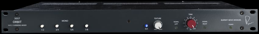
55057 Specifications
Input Impedance 16 kΩ
Frequency Response ZSOURCE = 40Ω Balanced, 30 ft. XLR Output Cable, 200k Termination
10 Hz to 50 kHz +/- 0.1dB typical
150 kHz -3dB typical
Noise (BW 22 Hz - 22 kHz, Un-terminated) -90 dBu typical
Maximum Input Level @ 1 kHz +26dBu typical
Maximum Output Level @ 1 kHz +26dBu typical
THD+N% BW 22 Hz - 22 kHz, Balanced Input to Main Out
0 dBu @ 1kHz 0.003% typical
+20 dBu @ 1kHz 0.0006% typical
Crosstalk BW 22 Hz - 22 kHz, Balanced Input to Main Output
1 kHz -103 dBu typical
10 kHz -93 dBu typical
Product Dimensions (W x D x H) 19” (48.3 cm) x 9” (22.9 cm) x 1.65” (4.2 cm)
Shipping Dimensions (L x W x H) 24” (61 cm) x 13” (33 cm) x 4” (10.2 cm)
Shipping Weight 10 lbs (4.5 kg)
65057 Frequency Response 7
This page intentionally left blank.

                                      8
PRODUCT WARRANTY
Rupert Neve Designs warrants this product to be free from defects in materials and workmanship for a period of one (1)
year from date of purchase, and agrees to remedy any defect identified within such one year period by, at our option,
repairing or replacing the product.
LIMITATIONS AND EXCLUSIONS
This warranty, and any other express or implied warranty, does not apply to any product which has been improperly
installed, subjected to usage for which the product was not designed, misused or abused, damaged during shipping,
damaged by any dry cell battery, or which has been altered or modified in any way. This warranty is extended to the
original end user purchaser only. A purchase receipt or other satisfactory proof of date of original purchase is required
before any warranty service will be performed. THIS EXPRESS, LIMITED WARRANTY IS IN LIEU OF ALL OTHER WARRANTIES,
EXPRESS OR IMPLIED, TO THE EXTEND ALLOWED UNDER APPLICABLE STATE LAW. IN NO EVENT SHALL RUPERT NEVE
DESIGNS BE LIABLE FOR ANY SPECIAL, INCIDENTAL, OR CONSEQUENTIAL DAMAGES RESULTING FROM THE USE OF THIS
PRODUCT. Some states do not allow the exclusion or limitation of consequential damages or limitations on how long
an implied warranty lasts, so this exclusion may not apply to you.
WARRANTY SERVICE
If you suspect a defect in this product, please call us at 512-847-3013 or email us at service@rupertneve.com to discuss
the suggested defect (it is possible that a suspected defect could be due to improper usage) and to obtain a return
authorization number. It shall be your responsibility to pay for shipping the product to us, and, if the product is
determined to be defective, our responsibility to pay for shipping the product back to you.
Rupert Neve Designs
PO Box 1969
Wimberley TX 78676
www.rupertneve.com
tel: +1 512-847-3013
775-00041 Rev A2
fax: +1 512-847-8869
9You can also read