EDS Series (late 2018) - Iseg-hv
←
→
Page content transcription
If your browser does not render page correctly, please read the page content below
Technical documentation
Last changed on: 17.06.2020

EDS Series (late 2018)
Distributor High Voltage Module with Common Floating Ground

  •   16 / 24 / 48 channel, 1kV – 3 kV versions
  •   Low cost version with reduced current measurement accuracy
  •   very low ripple and noise
  •   hardware voltage and current limit
  •   voltage control and current measurement per channel
  •   programmable parameters

                                      www.iseg-hv.com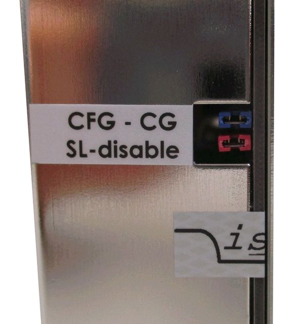
Document history
  Version        Date                Major changes

  3.2            17.06.2020          Figure for Jumper configuration (CG-CFG)

  3.1            26.03.2020          Improved documentation chapter Hardware Limit, Delayed Trip

  3.0            25.11.2019          safety information, glossary

  2.3            12.11.2019          Improved documentation

  2.2            06.09.2019          Configuration revised

  2.1            17.12.2018          Model revision “late 2018”, starting with Serial number: 7100001
                                     Technical data and configurations updated

  2.0            28.02.2017          Relayouted documentation
                 01.10.2018          Notes revised

 Disclaimer / Copyright
 Copyright © 2020 by iseg Spezialelektronik GmbH / Germany. All Rights Reserved.
 This document is under copyright of iseg Spezialelektronik GmbH, Germany. It is forbidden to copy, extract parts, duplicate for
 any kind of publication without a written permission of iseg Spezialelektronik GmbH. This information has been prepared for
 assisting operation and maintenance personnel to enable efficient use.
 The information in this manual is subject to change without notice. We take no responsibility for any mistake in the
 document. We reserve the right to make changes in the product design without reservation and without notification to
 the users. We decline all responsibility for damages and injuries caused by an improper use of the device.

EDS High Voltage Power Supply series | Last changed on: 17.06.2020 | www.iseg-hv.com                                               2/21
Safety
This section contains important security information for the installation and operation of the device. Failure to follow safety
instructions and warnings can result in serious injury or death and property damage.
Safety and operating instructions must be read carefully before starting any operation.
We decline all responsibility for damages and injuries caused which may arise from improper use of our equipment.
Depiction of the safety instructions
DANGER!
“Danger!” indicates a severe injury hazard. The non-observance of safety instructions marked as “Danger!” will
lead to possible injury or death.
DANGER!
WARNING!
“Warning!” indicates an injury hazard. The non-observance of safety instructions marked as “Warning!” could
lead to possible injury or death.
WARNING!
CAUTION!
Advices marked as “Caution!” describe actions to avoid possible damages to property.
CAUTION!
INFORMATION
Advices marked as “Information” give important information.
INFORMATION
Read the manual.
Attention high voltage!
Important information.
EDS High Voltage Power Supply series | Last changed on: 17.06.2020 | www.iseg-hv.com 3/21Intended Use
The device may only be operated within the limits specified in the data sheet. The permissible ambient conditions (temperature,
humidity) must be observed. The device is designed exclusively for the generation of high voltage as specified in the data sheet.
Any other use not specified by the manufacturer is not intended. The manufacturer is not liable for any damage resulting from
improper use.
Qualification of personnel
A qualified person is someone who is able to assess the work assigned to him, recognize possible dangers and take suitable
safety measures on the basis of his technical training, his knowledge and experience as well as his knowledge of the relevant
regulations.
General safety instructions
• Observe the valid regulations for accident prevention and environmental protection.
• Observe the safety regulations of the country in which the product is used.
• Observe the technical data and environmental conditions specified in the product documentation.
• You may only put the product into operation after it has been established that the high-voltage device complies with
the country-specific regulations, safety regulations and standards of the application.
• The high-voltage power supply unit may only be installed by qualified personnel.
EDS High Voltage Power Supply series | Last changed on: 17.06.2020 | www.iseg-hv.com 4/21Important safety instructions
WARNING!
To avoid injury of users it is not allowed to open the unit. There are no parts which can be maintained by users
inside of the unit. Opening the unit will void the warranty.
WARNING!
WARNING!
The high-voltage cable must be professionally connected to the consumer/load and the connection insulated
with the appropriate dielectric strength. Do not power the consumer/load outside of its specified range.
WARNING!
WARNING!
Before connecting or disconnecting HV cables or any operation on the HV output or the application, the unit has
to be switched off and discharge of residual voltage has to be finished. Depending on application residual
voltages can be present for long time periods.
WARNING!
WARNING!
Do not operate the unit in wet or damp conditions.
WARNING!
WARNING!
Do not operate the unit in an explosive atmosphere.
WARNING!
WARNING!
Do not operate the unit if you suspect the unit or the connected equipment to be damaged.
WARNING!
EDS High Voltage Power Supply series | Last changed on: 17.06.2020 | www.iseg-hv.com 5/21CAUTION!
When installing the units, make sure that an air flow through the corresponding air inlet and outlet openings is
possible.
Caution!
CAUTION!
When controlling, with software, the high voltage systems, make sure that nobody is near the high voltage or
can be injured.
Caution!
INFORMATION
Please check the compatibility with the devices used.
INFORMATION
EDS High Voltage Power Supply series | Last changed on: 17.06.2020 | www.iseg-hv.com 6/21Table of Contents
Document history 2
Disclaimer / Copyright 2
Safety 3
Depiction of the safety instructions 3
Intended Use 4
Qualification of personnel 4
General safety instructions 4
Important safety instructions 5
1 General description 8
2 Technical data 9
3 Handling 11
3.1 Connection 11
3.2 Module status 12
3.3 Hardware Limit 12
3.4 Safety Loop 12
3.5 Delayed Trip 13
4 Options 13
4.1 SLA – Active safety loop 13
4.2 SLP – Internally powered safety loop 13
5 Front panel versions 14
6 Dimensional Drawings 15
7 Connectors and PIN assignments 17
8 Accesories 18
9 Order guides 18
10 Appendix 19
11 Glossary 20
12 Warranty & service 21
13 Disposal 21
14 Manufacturer contact 21
EDS High Voltage Power Supply series | Last changed on: 17.06.2020 | www.iseg-hv.com 7/211 General description
CAUTION!
The devices must only be used in combination with iseg approved crates.
Caution!
EDS modules are cost effective distribution multichannel high voltage power supplies in MMS system (Eurocard format). The
modules are available as Standard version and as Low Cost version with a reduced resolution and precision of the current
measurement. EDS supplies come with common floating ground to reduce the voltage noise level. With up to 48 channels each
single channel has an independent voltage control. The modules are made of high precision components such as 24 bit ADC and
20 bit DAC and provide comprehensive security features. By offering different configurations and options this module perfectly
covers various types of applications such as detector supply, experimental setup or lab use.
EDS High Voltage Power Supply series | Last changed on: 17.06.2020 | www.iseg-hv.com 8/212 Technical data
SPECIFICATIONS EDS STANDARD EDS LOW COST
Polarity Factory fixed, positive or negative
Floating principle Common Floating Ground
Ripple and noise (f > 10 Hz) < 5 mVp-p
Ripple and noise (f > 1 kHz) < 2 mVp-p
Stablity
Stability − [ΔVout vs. ΔVin] < 1 • 10-5 Vnom
Stability − [ΔVout vs. ΔRload] < 5 • 10-5 Vnom
Long term stability (1h warmup) 24h < 1 • 10-5 Vnom
Temperature coefficient − Voltage measurement < 20 ppm / K
Temperature coefficient − Current measurement < 100 ppm / K
Set voltage limitation − If the maximum voltage of all channels in the module is greater 2000V the set accuracy, stability and
ripple and noise specifications are only guaranteed for set values of more than 10% of the maximum set voltage
Resolution − The resolution of measurable values depends on the settings of the sampling rate and the digital filter!
Resolution voltage setting 2 • 10-6 • Vnom
Resolution voltage measurement (1 2 • 10-6 • Vnom
Resolution current measurement (1 1 • 10-4 • Inom 5 • 10-4 • Inom
Measurement accuracy − The measurement accuracy is guaranteed in the range 1% • Vnom < Vout < Vnom and for 1 year
Accuracy voltage measurement ± (0.01 % • Vout + 0.02 % • Vnom)
Accuracy current measurement ± (0.1 % • Iout + 0.1 % • Inom) ± (1 % • Iout + 1 % • Inom)
Sample rates ADC (SPS) 5, 10, 25, 50, 60, 100, 500 (2
Digital filter averages 1, 16, 64 (2, 256, 512, 1024
Voltage ramp up / down up to 0.2 • Vnom / s | opt. up to 0.75 • Vnom / s
Hardware limits Potentiometer per module [Vmax and Imax]
Limit monitor voltage 2.5 V
Digital interface CAN (potential free)
Protection Safety loop, overload and short circuit protected
(ATTENTION: there is only one short circuit or arc per second allowed!)
HV connector R51 | SHV
System connector 96 PIN (MMS HV compatible, according to DIN 41612)
Safety loop connector Lemo 2pole
Limit monitor connector Lemo 1- and 2-pole
Case 19” plug-in cassette
Dimensions – L/W/H 220mm / 8HP / 6U
EDS High Voltage Power Supply series | Last changed on: 17.06.2020 | www.iseg-hv.com 9/21SPECIFICATIONS EDS STANDARD EDS LOW COST
Operating temperature 0 − 40 °C
Storage temperature -20 − 60 °C
Humidity 20 − 80 %, not condensing
Notes:
1)
The resolution of measurable values depends on the settings of the sampling rate and the digital filter!
2)
Standard factory settings
Table 1: Technical data: Specifications EDS
CONFIGURATIONS EDS SERIES
Type Vnom Inom Ch Max. Iin (A) at 24V HV connector Item code Options
Standard
EDS F1 10x 1 kV 1 mA 16 1.7 R51.46 ED161010x1050004300 SLA, SLP
EDS 18y 10x 1 kV 1 mA 24 2.6 R51.46 ED24y010x1050004300 SLA, SLP
EDS 30y 10x 1 kV 1 mA 48 5.2 R51.46 ED48y010x1050004300 SLA, SLP
EDS F1 30x 3 kV 500 µA 16 1.7 R51.46 ED161030x5040004300 SLA, SLP
EDS 18y 30x 3 kV 500 µA 24 2.6 R51.46 ED24y030x5040004300 SLA, SLP
EDS 30y 30x 3 kV 500 µA 48 5.2 R51.46 ED48ys030x5040004300 SLA, SLP
Notes:
16 channel modules in standard only
Table 2: Technical data: Configurations of EDS series
OPTIONS OPTION CODE EXAMPLE ITEM CODE HEX CODING
POLARITY Positive: x = p, EDS F1 10p
Negative x = n
STANDARD Standard: y=1 EDS F1 10p
LOW COST low cost: y=3 EDS F3 10p
ACTIVE SAFETY LOOP SLA 001
INTERNALLY SOURCED SAFETY LOOP SLP 002
Notes:
16 channel modules in standard only
Table 3: Technical data: Options and order information
EDS High Voltage Power Supply series | Last changed on: 17.06.2020 | www.iseg-hv.com 10/213 Handling
3.1 Connection
The supply voltages and the CAN interface are connected to the module via a 96-pin connector on the rear side of the module.
The physical address of the module, determined by the slot position in the crate, is also accessible via this connector Modules
and crate controllers with different settings of bit rate do not work on the same CAN-Line.
INFORMATION
Note: For proper operation the module must be configured with the correct CAN bitrate, which meets the
configuration of the crate controller, the module will be used with. The delivery condition is shown on the
modules typeplate (side plate of the module).
INFORMATION Typically newer iseg crate controllers (CC24, CC23, CC238) are delivered with 250 kBits/s standard.
Wiener M-POD Controller and older iseg hardware is set on 125 kBit/s standard bitrate.
INFORMATION
EDS modules with Common Floating Ground (CFG) will be delivered with a jumper, which connects the
module-GND with the crate-GND. To operate in CFG configuration the jumper (CG-CFG) on the module back
must be removed, see Figure 1: Jumper configuration on back side.
INFORMATION
Figure 1: Jumper configuration on back side
EDS High Voltage Power Supply series | Last changed on: 17.06.2020 | www.iseg-hv.com 11/213.2 Module status
The module status is displayed by two LEDs on the front panel
green LED „OK“ on all channels have the status “OK“.
green LED „OK“ off an error occured: safety loop is possibly not closed or the power supplies are out of
tolerance or the threshold of Vmax, Imax, Iset or Itrip (see function descriptions for details)
has been exceeded.
LED will be switched off until the error has been fixed and the corresponding status bit
has been erased via software interface.
yellow LED on one or more channels have status “HV ON” (voltage on output is greater than 56V).
Green LED blinking Firmware update is stored into flash, do not switch of power supply, crate etc.
Table 4: Module status information
3.3 Hardware Limit
The maximum output voltage for all channels (hardware voltage limit) is defined by the position of the corresponding
potentiometer Vmax. The maximum output current for all channels (hardware current limit) is defined by the position of the
corresponding potentiometer Imax . The highest possible set value for voltage and current is given by Vmax – 2% and Imax – 2%,
respectively. It is possible to measure the hardware voltage and current limits at the sockets below the potentiometer. The socket
voltages are proportional to the relative limits, where 2.5 V corresponds to 102 ± 2 % V nom and 102 ± 2% Inom. The output voltage is
limited to the specified value. If the current exceeds the hardware current limit (about 30% above the current limit value set by
the limit potentiometer) the channel will be shut off without delay and ramp. In both cases the green LED on the front panel
turns off.
3.4 Safety Loop
A safety loop can be implemented by the safety loop socket (SL) on the front panel and between the SLcontacts (Pin 22 and
PIN 30) at the REDEL-connector, if equipped. If the safety loop is active a high voltage generation in any channel is only possible if
the safety loop is closed and an external current in a range of 5 to 20 mA of any polarity is driven through the loop. For modules
with a REDEL-connector the front panel SL input must be shortened. If the safety loop is opened during the operation the output
voltages will be shut off without ramp and the corresponding bits in the “ModuleStatus” and “ModuleEventStatus” are cancelled
(see chapter 10 Appendix, “CAN_EDCP_Programmers-Guide.pdf”). After closing the loop again the “ModuleEventStatus” has to be
reset and the channels have to be switched ON. The loop connectors are potential free, the internal voltage drop is approx. 3 V.
By factory setup the safety loop is not active (the corresponding bits are always set). The loop can be activated by removing the
jumper “SL-disable” on the rear side of the module, see Figure 1: Jumper configuration on back side.
EDS High Voltage Power Supply series | Last changed on: 17.06.2020 | www.iseg-hv.com 12/213.5 Delayed Trip
The function "Delayed Trip" provides a user-configurable, time-delayed response to an increased output current (Iout) higher than
the set current (Iset). The response to this kind of event can be, for example, to ramp down the channel with the programmed
ramp. A detailed description for the configuration can be found in the manual “CAN_EDCP_Programmers-Guide.pdf”,
see chapter 10 Appendix.
By a programmable timeout with one millisecond resolution, the trip can be delayed up to four seconds. If the measured current
exceeds the set current the programmed timeout counter is decremented, keeping the output voltage. If the current returns to a
value < Iset before timeout the counter will be reset. So this process can be restarted if the current rises again.
Note that the actual current is acquired approximately every 150ms, which can lead to delays in the detection of an exceeded or
again reduced current.
If the current at any time exceeds the hardware current limit (about 30% above the current limit value set by the limit
potentiometer) the channel will be shut off without delay and ramp.
If the Delayed Trip function is activated the voltage ramp should be limited to 1 % of Vnom before. Higher values could trigger a trip
by internal charge balancing during a ramp, even though the output current does not exceed the set value I set.
If the connected load contains capacities or if Iset is very small, it might be necessary to further reduce the ramp speed.
Alternatively, the Delayed Trip can be activated only after the completion of the ramp.
INFORMATION
An activated KillEnable feature disables the Delayed Trip function.
INFORMATION
An active KillEnable function disables the Delayed Trip function. If KillEnable is active and a trip occurs, the channel is shut down
without ramp. However, the actual discharge time strongly depends on the connected load.
4 Options
4.1 SLA – Active safety loop
Actively opens the Safety loop in case of a trip or a delayed trip. This option allows to shut down other modules and devices by
interrupting the SL when a trip is detected.
4.2 SLP – Internally powered safety loop
Internal current source for the Safety Loop (no galvanic isolation of the SL and the crate GND).
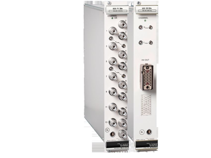
EDS High Voltage Power Supply series | Last changed on: 17.06.2020 | www.iseg-hv.com 13/215 Front panel versions FRONT PANELS Channels 16 24 / 48 Floating CFG CFG HV Connector SHV / S08 R51 Figure Table 5: Front panel versions EDS High Voltage Power Supply series | Last changed on: 17.06.2020 | www.iseg-hv.com 14/21
6 Dimensional Drawings

 Figure 2: Dimensional Drawing (ex. R51)

EDS High Voltage Power Supply series | Last changed on: 17.06.2020 | www.iseg-hv.com   15/21
Figure 3: Dimensional Drawing (ex. SHV)

EDS High Voltage Power Supply series | Last changed on: 17.06.2020 | www.iseg-hv.com   16/21
7 Connectors and PIN assignments
  HV CONNECTOR ASSIGNMENTS

  Name                    R51.44 (REDEL)                             R51.46 (REDEL)                              SHV / S08

  Figure

             SAFETY LOOP                                LIMIT MONITOR                              LIMIT MONITOR

  Name       Safety Loop socket                         Limit monitor socket 2pol                  Limit monitor socket 1pol

  Figure

 Table 6: Connector and pin assignments

  CONNECTORS PART NUMBERS (manufacturer code / iseg accessory parts item code)
                           POWER SUPPLY SIDE                                                        CABLE SIDE

                                                           R51 (REDEL 51 PINS)

               Socket                          SLG.H51.LLZG                        Connector                      SAG.H51.LLZBG

      Socket contacts (male)              FFA.05.403.ZLA1 / Z592189      Connector contacts (female)        ERA.05.403.ZLL1 / Z592263

   Contacts Safety Loop (male)            FGG.2B.565.ZZC / Z592261      Contacts Safety Loop (female)       EGG.3B.665.ZZM / Z592262

                                                                                Socket Load Side             SLA.H51.LLZBG / Z201035

                                                           SHV (ROSENBERGER)

               Socket                          57S501-200N3                        Connector                 57K101-006N3 / Z590162

                                                                S08 (RADIALL)

               Socket                           R317.580.000                       Connector                  R317.005.000 / Z592474

                                                            Safety Loop (LEMO)

               Socket                          ERA.0S.302.CLL                      Connector                FFA.0S.302.CLAC / Z592312

                                                        Limit monitor 1pol. (LEMO)

               Socket                          ERN.00.250.CTL                      Connector               FFA.00.250.CTAC31 / Z200793

                                                        Limit monitor 2pol. (LEMO)

               Socket                          EGG.00.302.CLL                      Connector                FGG.00.302.CLAD / Z201466

 Table 7: Connectors part number information

EDS High Voltage Power Supply series | Last changed on: 17.06.2020 | www.iseg-hv.com                                                     17/21
8 Accesories
CAUTION!
Only use genuine iseg parts like power cables, CAN cables and terminators for stable and safe operation.
CAUTION!
ACCESSORY ITEM ORDER ITEM CODE
REDEL Socket contact, ERA.05.403.ZLL1 Z592263
REDEL SL sockets Contact, EGG.3B.665.ZZM Z592262
REDEL socket carrier red SLA.H51.LLZG Z201035
SHV coupler screw for RG58 Z590162
SHV coupler screw for RG58, >5kV Z592474
Lemo plug 2-pole without collet chuck (SL) Z592312
1-pin LEMO connector FFA.00.250.CTAC31 Z200793
2-pin LEMO connector, FGG.00.302.CLAD30 Z201466
9 Order guides
CABLE ORDER GUIDE
POWER SUPPLY SIDE CABLE CABLE DESCRIPTION LOAD SIDE ORDER CODE
CONNECTOR CODE CONNECTOR LLL = length in m (1
R51.44-G 07 HV cable 6kV Kerpen SL-v2YCeHI 37xAWG26/7red R51.44-A RG44_C07-LLL_RA44
R51.46-G 08 HV cable 6kV Kerpen SL-v2YCeHI 56xAWG26/7red R51.46-A RG46_C07-LLL_RA46
SHV 04 HV cable shielded 30kV (HTV-30S-22-2) open SHV_C04-LLL
Notes:
1)
Length building examples: 10cm ➜ 0.1, 2.5m ➜ 2.5, 12m ➜ 012, 999m ➜ 999
Table 8: Guideline for cable ordering
CONFIGURATION ORDER GUIDE (item code parts)
ED 48 1 030 P 504 000 02 00
High Numbers Class Vnom Polarity Inom (nA) Option (hex) HV-Connector Customized
Voltage, of Version
Distributor channels
1 = normal three significante p = positive two significante Sum of the hex 02 = SHV 00 = none
Current digits • 100V n = negative digits + number codes (see Table 03 = S08
Measurement For Examle: of zeros 3: Technical 44 and 46 =
3 = Low Cost 030 = 3000V For Examle: data: Options Redel Multipin
Current 305 = 3mA and order (see 7 Connectors
Measurement information) and PIN
For Example: assignments )
SLP = 002
Table 9: Item code parts for different configurations
EDS High Voltage Power Supply series | Last changed on: 17.06.2020 | www.iseg-hv.com 18/2110 Appendix For more information please use the following download links: This document http://download.iseg-hv.com/SYSTEMS/MMS/EDS/iseg_datasheet_EDS_en.pdf CAN-EDCP Programmers-Guide http://download.iseg-hv.com/SYSTEMS/MMS/CAN_EDCP_Programmers-Guide.pdf iseg Hardware Abstraction Layer http://download.iseg-hv.com/SYSTEMS/MMS/isegHardwareAbstractionLayer.pdf EDS High Voltage Power Supply series | Last changed on: 17.06.2020 | www.iseg-hv.com 19/21
11         Glossary
  SHORTCUT                         MEANING

  Vnom                             nominal output voltage

  Vout                             output voltage

  Vset                             set value of output voltage

  Vmon                             monitor voltage

  Vmeas                            digital measured value of voltage

  Vp-p                             peak to peak ripple voltage

  Vin                              input / supply voltage

  Vtype                            type of output voltage (AC, DC)

  Vref                             internal reference voltage

  Vmax                             limit (max.) value of output voltage

  ∆Vout – [∆Vin]                   deviation of Vout dep. on variation of supply voltage

  ∆Vout – [∆Rload]                 deviation of Vout dep. on variation of output load

  Vbounds                          Voltage bounds, a tolerance tube Vset ± Vbounds around Vset.

  Inom                             nominal output current

  Iout                             output current

  Iset                             set value of output current

  Imon                             monitor voltage of output current

  Imeas                            digital measured value of current

  Itrip                            current limit to shut down the output voltage

  Iin                              input / supply current

  Imax                             limit (max.) value of output current

  Ilimit                           Current Limit.

  Ibounds                          Current bounds, a tolerance tube Iset ± Ibounds around Iset.

  Pnom                             nominal output power

  Pin                              input power

  Pin_nom                          nominal input power

  T                                temperature

  TREF                             Reference temperature

  ON                               HV ON/OFF with voltage ramp

  /ON                              HV OFF/ON with voltage ramp

  CH                               channel(s)

  HV                               high voltage

  LV                               low voltage

  GND                              signal ground

  INH                              Inhibit

  POL                              Polarity

  KILL                             KillEnable

EDS High Voltage Power Supply series | Last changed on: 17.06.2020 | www.iseg-hv.com              20/21
12       Warranty & service
 This device is made with high care and quality assurance methods. The standard factory warranty is 36 months. Please contact
 the iseg sales department if you wish to extend the warranty.

  CAUTION!

                 Repair and maintenance may only be performed by trained and authorized personnel.

                 For repair please follow the RMA instructions on our website: www.iseg-hv.com/en/support/rma

    CAUTION!

 13       Disposal
  INFORMATION

                  All high-voltage equipment and integrated components are largely made of recyclable materials. Do not
                  dispose the device with regular residual waste. Please use the recycling and disposal facilities for electrical and
                  electronic equipment available in your country.

  INFORMATION

 14       Manufacturer contact
 iseg Spezialelektronik GmbH
 Bautzner Landstr. 23
 01454 Radeberg / OT Rossendorf
 GERMANY
 FON: +49 351 26996-0 | FAX: +49 351 26996-21
 www.iseg-hv.com | info@iseg-hv.de |sales@iseg-hv.de

EDS High Voltage Power Supply series | Last changed on: 17.06.2020 | www.iseg-hv.com                                                    21/21
You can also read