Digital Power Line Carrier Utility Communications Center
←
→
Page content transcription
If your browser does not render page correctly, please read the page content below

Digital Power Line Carrier
          Utility Communications Center

Unique Features

• The UCC 2021D is a self-contained Digital Power Line Carrier equipment
  comprising integrated F6 teleprotection and premium voice and data
  communications.
• Various embedded protocols allow IP connectivity, therefore, easy integration
  in any digital network.
• WAN Gateway over the High Voltage Power Lines.
• Numerically Programmable, local or remote, from Carrier frequency of 20 to
  500 Khz, there is no components to change in the field.
• High Quality telephone traffic and multiple data channels of variable rate.
• Extremely reliable Digital Power Line Carrier link based in a state of the art
  Adaptive QAM and Channel Equalization.
• 50 or 100 Watt PEP output power.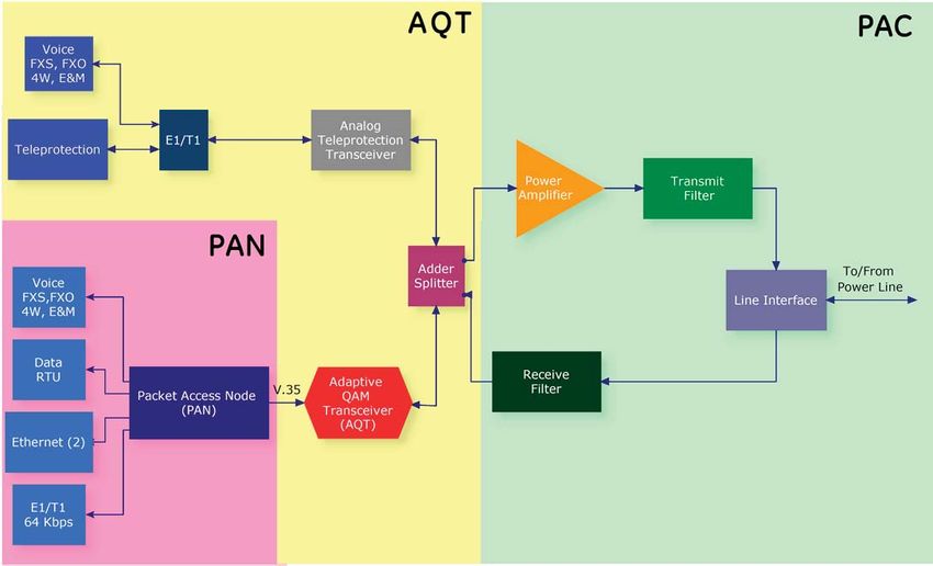
System Overview                                                            The UCC 2021D offers a choice of two power output levels, Imped-
                                                                           ance Adapter, Loopback Test, Programmable RF filters, Skewed Hybrid,
The Utility Communication Center (UCC 2021D) is a complete Digital         Dummy Load and Power Monitor.
Power Line Carrier equipment comprising four integrated subsystems:        The UCC 2021D integrates a plug-in F6 Teleprotection Module (F6T)
                                                                           complying with the IEC-60834 teleprotection standard, integrated test
• Power Amplifier and Coupling (PAC)                                        switch, selectable unblock logic and integrated SOE and Trip Counters.
• Adaptive QAM Transceiver (AQT)                                           The equipment is designed to operate in the harsh environment of elec-
• F6 Teleprotection (F6T)                                                  tric utility substations, based on the successful and proven UCC 2020
• Packet Access Node (PAN)                                                 E1/T1 Multiplexer used by thousands in high-voltage power networks
                                                                           around the world.
The UCC 2021D unique features incorporate the latest Digital Signal        A versatile Windows® GUI (Graphical User Interface) allows the user to
Processing technology (DSP) making a rugged Adaptive QAM transceiv-        configure the various parameters via a local or remote computer. SNMP
er, along with a unique Digital Packet Network Multiplexer Node (PAN)      alarm reporting traps are also supported if required.
that integrates voice, data, multiple T1 or E1 data ports, and IP traffic
over the Digital Power Line Carrier link.                                  UCC2021D Equipment Architecture
The UCC 2021D system utilizes QAM modulation, proven to be the most
robust and reliable method for Digital Power Line Carrier Systems. The     The modularity of the UCC 2021D allows high flexibility to comply with
QAM adaptability with channel equalization and echo canceling makes        different requirements; as per Fig 1:
the UCC 2021D the most flexible and dependable Digital Power Line           There are three physical shelves, enclosing the PAN, AQT and PAC
Carrier System in the market today.                                        respectively.
The UCC 2021D Adaptive QAM Transceiver (AQT) transmission channel          We have the Analog and the Digital path, both working concurrently
occupies a total bandwidth of 8 KHz. This feature allows the replace-      but independent of each other . In the Analog Path the different types
ment of analog PLC systems, not just improving the overall perfor-         of voice channels and the F6 Teleprotection are connected to an Analog
mance and interfaces but using the existing frequency assignments.         Tranceiver via an E1/T1 Multiplexer Module. In the Digital Path, the vari-
The Adaptive QAM Transceiver (AQT) system is able to operate at a re-      ous voice and data interfaces, the two Ethernet Ports, the 64 Kbps Port
duced rate in a bandwidth of 4 KHz using algorithms for error detection    the E1/T1 Ports, as well as the V.35 High Speed Serial Port converged in
and correction in order to achieve better performance in the presence      the PAN where the digital stream interconnects with the QAM Transceiv-
of power line channel noise.                                               er. Both Transceivers are adde or splitted, depending on the path direc-
Transmission is carried out at a gross bit rate of 64 Kbps where 2.6       tion, being Transmission or Reception. For Transmission the combined
Kbps is used for synchronization leaving 62.4 kb/s available for the       low level RF signal feed the Power Amplifier, the Transmission Filter and
Packet Access Node through a V.35 interface.                               finally the Line Interface, for Reception the combined RF signal is taken
The UCC 2021D Packet Access Node (PAN) excels an adaptive 64kbps           from the Line Interface to the receive Filter.
digital data stream; multiplexing voice, data, T1, E1, and IP streams      All the Power Line Carrier configuration is done in the Transceivers,
to provide the user with flexibility not yet seen in Power Line Carrier     and the Networking configuration is performed in the PAN. The typical
Systems.                                                                   Digital PLC will not require of the Analog Voice and data Channels.

                                                          Figure 1. Equipment Architecture
UCC2021D Equipment description                                                      • Modulation: It is an Adaptive Trellis Code Modulation with Multidi-
                                                                                      mensional Error Correction resulting in fractional bits per symbol,
Power Amplifier and Coupling (PAC)                                                     from 4 QAM to 1024 QAM, depending on the Power Line Conditions
                                                                                      and Bandwidth available.
The PAC chassis comprises the 50 or 100 Watts Peak Envelope Power                   • Programmable RF Test Generator, the Transceiver can generate an
(PEP), RF Filters, Dummy Load, Power Monitor, RF Impedance Adapter,                   RF test tone between 20 and 500 kHz to be transmitted over the
Loop Back test Module and RF Skewed Hybrid. The RF Interface is                       power line carrier path.
located at the top in the PAC chassis. Test points are found inside the
front panel: Line Tx (after transmit filter), Line Rx (before front-end filter)     Packet Access Node
and Line (after the Hybrid), These signals facilitate equipment testing ad
commissioning. The Skewed Hybrid efficiently separates the send and                 The UCC 2021D is a Utility Communications Center (UCC) because of
receive frequencies. Use of a skewed hybrid keeps losses in the send              its unique ability to integrate voice and data traffic across a single,
direction very low, in the order of 0.5 to 1 dB.                                  converged network utilizing a multi-service access gateway that uses
                                                                                  data packets switched for distributed substation utility applications, the
                                                                                  UCC2021D PAN Highlights are:

                                                                                    • Delivers High Quality Over Narrow Bandwidth : The UCC 2021D
                                                                                      PAN offers state of the art prioritization and voice/data compres-
                                                                                      sion technology performing superior quality of service with minimal
                                                                                      bandwidth utilization, providing high compression voice and data
                                                                                      transport over the High Voltage Power Lines. The versatility of the
                                                                                      UCC 2021D helps to take advantage of the narrow bandwidth avail-
                 Fig 2A, Power Amplifier and Coupling, PAC                             able over the Power Lines without sacrificing quality of service for
                                                                                      voice and data applications.
                                                                                    • Any-to-Any Voice Switching: The UCC 2021D PAN integrates
Adaptive QAM Transceiver (AQT)
                                                                                      the disparate phone systems of individual sites; with support for
The Transceiver, the E1/T1 Common Module and the F6 Teleprotection                    both analog and digital voice, allowing legacy and packet data
are mounted in an additional 19” wide chassis. The connection between                 equipment sharing the Power System Network. Analog and digital
the Transceiver and the Common Module is an E1 or T1 connection.                      telephony channels as well as multiple T1/E1 data interfaces and
This transceiver is intended for use on connections on Power Line Car-                serial data ports are supported by the UCC 2021D PAN. These are
rier Systems on point-to-point, mesh, hierarchical or star topology. The              optimized specifically for distributed enterprise networks that have
principal characteristics of the Transceiver are as follows:                          needs for multiple WAN connectivity requirements and different
   • Duplex mode of operation.                                                        needs for functionality, density, performance and connectivity.
   • Channel separation by echo cancellation techniques;
   • Adaptive Quadrature Amplitude Modulation (QAM) for each channel
     with synchronous line transmission at selectable symbol rates
     of 2400, 2743, 2800, 3000, 3200, 3249 symbols/s.
   • Depending on the Power Line Conditions, the following standard
     Synchronous channel data signaling rates can be achieved: 64.000
     bit/s; 62.400 bit/s; 33 600 bit/s; 28 800 bit/s; 14 400 bit/s; 4800 bit/s;
     2400 bit/s;
   • Trellis coding for all data signaling rates;
   • Adaptive techniques that enable the modem to achieve close to
     the maximum data signaling rate the channel can support on each
     connection;
   • Exchange of rate sequences during start-up to establish the data
     signaling rate.

                                                                                                      Fig 2C, Packet Access Node, PAN

                                                                                    • Simplified Network Management: Utilizing versatile software the
                                                                                      UCC 2021D PAN is easy to configure and manage, integrating with
                                                                                      multivendor network management systems via SNMP-compli-
                                                                                      ant MIBs and user friendly Windows graphical management. The
                                                                                      UCC2021D PAN is extremely flexible and easy to configure and
                  Fig 2B, Adaptive QAM Transceiver, AQT                               manage. As a modular voice and data solution, the UCC 2021D PAN
                                                                                      platform delivers ease of use and scalability in a fully integrated,
                                                                                      stand-alone form factor by efficiently packetizing and compressing
   • Automatic Gain Control (AGC) to compensate for variations in sig-                telephony traffic and delivering it.
     nal level caused by line attenuation changes. If the Teleprotection            • Supports Industry Standards: UCC 2021D PAN supports standards-
     received signal level varies more than 40 dB from normal in the                  based Voice Over IP (VoIP) via the SIP protocol and a wide range of
     regulation range of -20 to +20 dB or -26 to +14 dB, a relay and LED              voice codecs, providing interoperability for multi-vendor and mixed
     will indicate an alarm. Additionally the AGC functions to perform                private/public networks. Seamless interconnectivity is not limited to
     the signal-to-noise squelch which disables the system and initi-                 voice, however, the UCC 2021D PAN also offers flexible data protocol
     ates an alarm under excessive noise conditions.                                  support and interfaces with a wide range of SCADA, network ser-
                                                                                      vices and user requirements.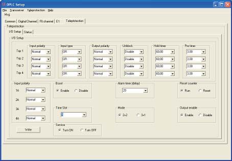
PLC System Planning

A good planning for a Digital Power Line Carrier System will depend on
many factors like the Signal to Noise ratio (SNR), the Bandwidth available
and the services needed.
To help in this planning we provide the following BER curve, based on large
number of simulation, lab and field tests.

     From the curve, an SNR of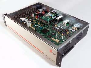
Integrated F6 teleprotection                                                 Many times the protective relays are not located in the same building
                                                                             as the communications systems that are used to transmit the relaying
The UCC 2021D is available with an integrated teleprotection. This           signals. A unique feature of the UCC 2021D is that the Teleprotection mod-
system use a four function plug-in Modular Transfer Trip System (MTS)        ules can be housed in a separate chassis and communicate with the UCC
based on the proven F6 protection scheme.                                    2021D via fiber optic cable The Teleprotection chassis can be located up to
The system is suitable for Direct Transfer Trip (DTT), Permissive Transfer   113km (70 miles) from the UCC 2021D depending on the type of fiber optic
Trip (PTT), Blocking and Unblocking applications. The UCC2021D comply        transceiver selected. This chassis is known as the UCC 2021 RT.
to the IEC-60834 teleprotection standard.
The MTS system is comprised of two parts, the MTS module and the I/O         Integrated Test Switch
modules. Together these modules work with the balance of the UCC             The MTS module supports the connection of an internal test panel. The
2021D system to provide four-function teleprotection. Up to two MTS          test panel can be mounted inside the door of the chassis and connect to
modules can be used in each system to provide up to eight functions          the MTS via an 8 wire cable. The test panel has a 10 position rotary switch,
of teleprotection. The MTS module senses the inputs, de-bounces them,        a push-button, and two-toggle switches. The rotary switch has Normal,
applies a small amount of logic, and passes them in a timeslot on the        Input #1, Input #2, Input #3, and Input #4 positions. The test switch can
E1/T1 link to the transceiver. The MTS limits commands to 2 seconds,         accommodate 2 MTS cards. Selecting input 1 through 4 positions will
returning to the guard states after that time, even if the inputs remain     not do anything until the push-button is pressed. Pressing the push-but-
keyed. The MTS user interface is in the UCC2021D NMS. Two and four           ton will send the command corresponding to the selected position. The
function relay and solidstate I/O’s are available. Additional I/O for        toggle switch disables the local outputs. Depending on the mode and
providing parallel contacts is also supported. The PLC transceiver DSP       the command, the transceiver sends one frequency for the entire time or
decodes the message from the MTS and creates the necessary tones             switches back and forth between two frequencies. The single frequency
to transfer the command to the other end. The other end receives the         is considered un-coded operation. Un-coded is less secure and is used for
tones, performs the necessary actions to generate the needed security        permissive or blocking applications. Coded transmission consists of two
and dependability, and sends the information to the MTS via the E1/T1        frequencies sent one after the other for a specified time. The receiver must
link.                                                                        receive each tone for a specified time period before declaring a valid trip
                                                                             reception. Once the receiving DSP has determined that a valid trip has
General                                                                      been received, the RX trip command is sent to the MTS where it is decoded
F6 teleprotection is a single tone system that sends only one tone at a      into output contacts according to a user
time, making it ideal for PLC. Different combinations of inputs use a pri-
ority scheme to generate the correct tone and the correct output on the      Selectable Unblock Logic
receiving side. This system can have two, four or eight inputs and out-      In the event that the receiver enters an alarm state, the outputs pro-
puts, which are programmable. Each input can be optionally inverted or       grammed for unblocking will go active after 20 ms and will remain active
not and if 8 inputs are employed, paired inputs can be AND’ed or OR’ed       for 150 ms.
to form each of the 4 command inputs. Once the input commands have
been determined, the transmitted command is determined according to          Integrated SOE
the priority chart. Two charts are available, based on the mode setting,     The MTS stores up to 100 events including; Time/Date, and Input/Output
“2+2” which provides four commands with priority or “3+1” which pro-         contact status.
vides three independent and simultaneous commands. The 2+2 mode is
typically used for parallel line applications, while the 3+1 mode is typi-   Trip Counters
cally used for single pole trip applications. The transmitted command is     Trip counters record how many times each command is sent or received.
sent to the PLC transceiver after an appropriate de-bounce period.           The counters roll over after 255 counts.

    INPUT         TX Command         Frequency        Receiver                  INPUT           TX Command           Frequency           Receiver
  COMMAND          (actual TX)       (2 / coded)      outputs                 COMMAND            (actual TX)         (2 / coded)         outputs

   No Input           None             Guard           None                     No Input            None               Guard               None
       A                S                F2               A                        A                  A                  F3                  A
       B                B                F5               B                        B                  B                  F5                  B
     A&B               A&B               F7             A&B                       A&B                 D                  F7                A&B
       C                C               F2,F4             C                        C                  C                  F2                  C
       D                D               F2,F6           C&D                       B&C                 D                  F4                B&C
     A&D               A&D              F6,F8           A&D                       A&C                 D                  F1                A&C
     B&C               B&C              F4,F8           B&C                     A&B&C                 D                  F6               A&B&C
     A&C                C               F2,F4             C
                                                                                        Figure 5. Command Priority Table for “3+1” Mode
     B&D                D              F2&F6             D
    A&B&C              B&C              F4,F8           B&C
    A&B&D              A&D              F6,F8           A&D
    A&C&D              C&D              F4,F6           C&D
    B&C&D              C&D              F4,F6           C&D
  A&B&C&D              C&D              F4,F6           C&D

     Figure 4. Command Priority Table for “2+2” Mode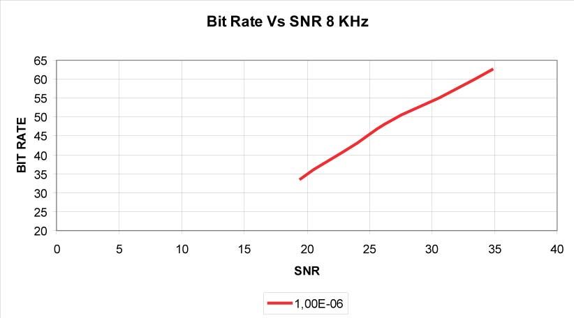
Man Machine Interface
  • A Windows® (W95, W98, ME, W2000, NT and XP) program allows the user to configure all UCC2021D parameters; the channel mapping for
    the Teleprotection, load the carrier frequency to the NCO, adjust output power level, as well as to measure the SNR, alarms, etc.
  • All the settings are saved in a file for future use or reference.
  • The configuration can be done locally or remotely
  • Easy and practical distribution of the parameters categories avoiding mistakes during the system configuration/review.

Two operation modes “USER” and “ADMIN” provides protection of critical settings which are not required to be modified in a normal mainte-
nance or supervision routine avoiding system shutdown due to incorrect configuration.

                                                                     Figure 6

        For better understanding of the system, the GUI is classified in a similar way as the hardware distribution, so that the E1 interface,
        Teleprotection and QAM transceiver will be configured separately.

                                Figure 7                                                                     Figure 8

                 The adaptive feature of the QAM modulation could be specified among a few or all of the available data rates.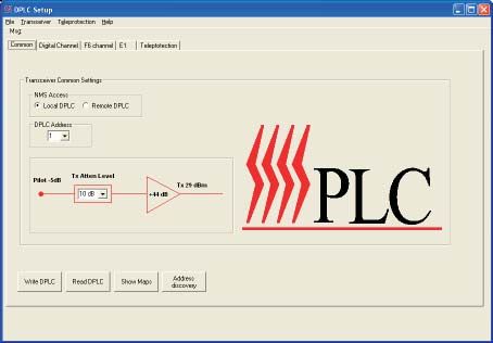
Technical Specifications
RF Band                                                                            Network Signalling:
                                                                                   • Analog Telephony channels:      FXS: loop and ground start, forward
  Frequency range:                   20 to 500 kHz                                                                   disconnect, caller ID generation.
  Modulation:                        Adaptive QAM with Channel equalization                                          FXO: loop start, forward disconnect and
  Raw data Speed:                    64 KBps@8Khz                                                                    caller ID detection
  Full duplex Channels:              1 RF Channel                                                                    E&M: immediate and wink start
  Channel Bandwidth:                 2.5 kHz, 4 kHz, 8 kHz                         • Digital telephony channels:     T1 signaling: robbed bit signaling
                                     with or without superimposed bandwidth                                          E1 signaling: CAS
  Selectivity:                                                                     • Digital CAS Signaling types:    Immediate, Wink, FXO, FXS, FXO ground,
   Overall (4 kHz from Band-edge)
USA
201 Alhambra Circle, # 502,
Coral Gables, FL 33134; USA
Tel (786) 552 0035
Fax (786) 552 0037
email: plci@plcpower.com
Venezuela
Calle 8, Edif PLC
Caracas; MI 1073
Venezuela
Tel (582) 212 243 6055
Fax (58) 212 243 6064
email: info@plc.com.ve
Chile
Barros Errázuriz 1953, Piso 7,
Providencia, Santiago, Chile
Tel (562) 397 6000
Fax (562) 269 8728
email: contacto@plci-ge.comYou can also read