5G WIRELESS INFRASTRUCTURE SEMICONDUCTOR ANALYSIS
←
→
Page content transcription
If your browser does not render page correctly, please read the page content below

5G WIRELESS
INFRASTRUCTURE
SEMICONDUCTOR
ANALYSIS

           SIA CONFIDENTIAL | 5G INFRASTRUCTURE ANALYSIS | 1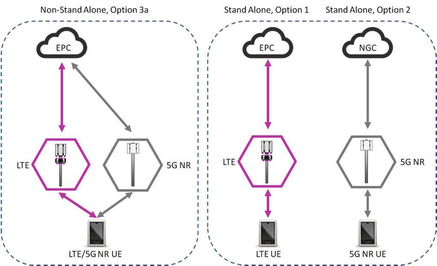
2 | 5G INFRASTRUCTURE ANALYSIS
EXECUTIVE
                           SUMMARY
                           On behalf of SIA, a wireless market
                           intelligence firm has analyzed all of the
                           semiconductor function product families
                           within the key elements of a 5G radio access
                           network (RAN)- baseband unit (BBU) and
                           active antenna unit (AAU)/remote radio unit
                           (RRU) systems for 5G base stations along
                           with the current domestic United States and
                           foreign/international semiconductor
                           suppliers.

                           Our conclusion is that despite the United
                           States maintaining overall market-share
                           leadership in semiconductors with a 45%
                           share of the global market, substitutes
                           for U.S. components exist for nearly every
                           semiconductor product family required to
                           build a complete RAN infrastructure. In fact,
                           our analysis indicates that of the more than
                           fifty critical semiconductor elements
                           necessary to design, manufacture, and sell a
                           competitive 5G RAN network1, only 3
                           components could face supply constraints
                           outside the United States in the event of
                           an export restriction. For each of those
                           three components, we have further
                           concluded that alternatives are currently
                           being deployed or under active development,
                           especially within China by Huawei’s
                           semiconductor design arm, HiSilicon.
8 | 5G INFRASTRUCTURE ANALYSIS | SIA CONFIDENTIAL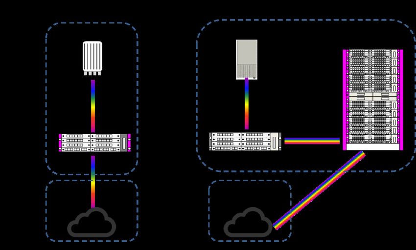
OUR CONCLUSION FOR THE BASEBAND UNIT
SYSTEM FOR A 5G BASE STATION IS THAT THE
TWO KEY SEMICONDUCTOR PRODUCT FAMILIES
THAT MAY PRESENT SUPPLY ISSUES OUTSIDE
OF THE UNITED STATES ARE:
• Commercial off-the-shelf Field Programmable Gate Arrays (FPGAs)
• 10Gbps Ethernet PHY Transceivers/Switches

This is based upon current available information regarding foreign/
international semiconductor suppliers, their current products,
and performance metrics. For FPGAs, this bottleneck only applies
to merchant FPGAs, as several BBU vendors including Huawei, Ericsson,
and Nokia have long had internal capability to develop their own
Application Specific Integrated Circuits (ASICs) that can replicate
the minimum necessary requirements of an FPGA within a baseband
unit. This is called the ASIC crossover, as vendors first deploy FPGAs
in initial product release then deploy ASICs to reduce costs and improve
power efficiency. These ASICs are designed in-house with fabrication
outsourced to leading foundries, typically at the 14nm FinFET node
ASICs for wireless infrastructure are developed on the same advanced
process nodes as merchant chips. Deploying an ASIC as opposed
to an FPGA does not degrade the overall functionality of the BBU.
For merchant FPGAs, we note that state-of-the-art process nodes are
at 7nm FinFET using Taiwan Semiconductor Manufacturing Company
(TSMC) silicon foundry services. Current state of the art FPGAs available
from Chinese domestic suppliers are at a 28nm process node. While it
is logical that foreign FPGA suppliers have access to all of the process
nodes at TSMC, Chinese suppliers will likely attempt to develop
and scale FPGA designs to be on par with the U.S.-based suppliers.

1
  For the purposes of this report we identified only semiconductor components deemed “critical” to aspects
of a 5G RAN network. Critical is defined as essential for the design, manufacturing, and sale of 5G RAN equipment
and possessing technical performance parameters unique to 5G networks.

                                                                                  5G INFRASTRUCTURE ANALYSIS | 4
EXECUTIVE SUMMARY

           For Gigabit Ethernet PHY transceivers and switches, we note the availability of 1Gbps
           Ethernet PHY transceiver and switch solutions from foreign/international semiconductor
           suppliers but no availability for 10Gbps Ethernet PHY transceiver and switch solutions
           outside the U.S. Within the 5G base station systems, the 10GE standard is predominantly
           used for optical/electrical transport functions. We understand that China-based suppliers,
           as identified in this report, are rapidly closing the gap between their current capability of
           1Gbps to 10Gbps, and we project the gap can be closed in the next eighteen months.

           We are convinced time is the only issue for development of non-U.S.-based designs and
           availability for these two functional product families. Non-U.S. based chip designs will
           continue to have access to leading semiconductor electronic design automation (EDA) tools
           and the best semiconductor foundries, enabling rapid development and manufacturing.
           We are also convinced the amount of investment capital available in China is not an issue
           in preventing the evolution of the domestic semiconductor design industry.

                  EXHIBIT 1: BBU FUNCTION PRODUCT FAMILY BOTTLENECK ANALYSIS
                                                                        Memory
            Fronthaul Optical             L1-L3 Baseband                SDRAM    Clock Gen/Dist     Power
                                   FPGA                     Switches                                           Power Conversion
                Modules                     Processing                   Flash      Std Logic     Management
                                                                       EEPROM

                                                           10 GE PHY

                      Bottleneck

                      No Supply Issue

           OUR CONCLUSION FOR THE AAU/RRU SYSTEM FOR A 5G BASE
           STATION IS THAT THERE IS ONLY A SINGLE POTENTIAL SUPPLY
           CONSTRAINT, AGAIN BEING THE FPGA. ALTHOUGH, AS NOTED
           ABOVE, VENDORS SUCH AS HUAWEI HAVE ALREADY DEVELOPED
           ASIC SOLUTIONS THAT REPLACE THE FUNCTIONALITY OF THE
           FPGA. IN EFFECT, THIS POTENTIAL SUPPLY CONSTRAINT DOES
           NOT IMPACT HUAWEI, BUT COULD IMPACT OTHERS.

5 | 5G INFRASTRUCTURE ANALYSIS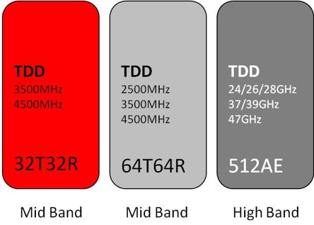
Similar to our outlook for research and development of such semiconductor products, it is
simply time and money, neither of which is limited from the perspective of the domestic Chinese
semiconductor design industry. We do not have a timeline as to how quickly and when such
products will become available at the same performance as current U.S.-supplied solutions.

For radio frequency (RF) functions such as power amplifiers, GaN has been identified as a
key enabler for 5G radio systems due to the inherent wider bandwidth of operation as well as
thermal performance. Additionally, we believe that the current evolution of 4G radio systems
will also require GaN technology to achieve optimal performance. We believe that foreign/
international availability of GaN power amplifiers is sufficient and will not be a supply chain
issue currently. We also note that while domestic Chinese supply of GaN may be performance
limited, research and development will not be impacted by a lack of investment capital.

   EXHIBIT 2: AAU/RRU FUNCTION PRODUCT FAMILY BOTTLENECK ANALYSIS

Fronthaul Optical               Digital Front End       Analog         Clock Gen/Dist     Power                          Isolator     RF Filter    Antenna
                       FPGA                                                                          Power Conversion
    Modules                      Beamforming           Front End          Std Logic     Management                      Circulator   Multiplexer    Array

  CPRI/eCPRI                    A/D Converters
                       RF SoC                       Power Amplifiers
   Fronthaul                    D/A Converters

                                                       Low Noise
                                                       Amplifiers

          Bottleneck

                                                      RF Switches
          No Supply Issue

                                                                                                                                     5G INFRASTRUCTURE ANALYSIS | 6
EXECUTIVE SUMMARY
The potential for development of domestic Chinese semiconductor
products is based upon access to semiconductor foundries for silicon,
silicon germanium (SiGe), silicon on insular (SOI), gallium arsenide (GaAs),
indium phosphide (InP), silicon carbide (SiC), and gallium nitride (GaN)
semiconductor materials.
WE NOTE THE FOLLOWING NON-U.S. BASED COMPOUND
SEMICONDUCTOR FOUNDRIES AND THEIR LOCATIONS:
• Advanced Wireless Semiconductor Company (Taiwan)
• Global Communications Semiconductors (U.S., Taiwan)
• OMMIC S.A. (France)
• United Monolithic Semiconductors (France)
• Wavetek Microelectronics Corporation (Taiwan)
• WIN Semiconductor (Taiwan)
• Sanan Integrated Circuits (China)
WE ALSO NOTE THE FOLLOWING NON-U.S. BASED SiGe
FOUNDRIES AND THEIR LOCATIONS:
• Innovation for High Performance (Germany)
• Tower Jazz (U.S., Japan, Israel)
We believe that any potential supply chain bottlenecks to the specific
semiconductor functional products highlighted in this analysis is merely
a temporary “blip” in the supply chain. While there may be some level of
disruption and performance degradation due to the unavailability of these
specific products, we expect that these issues will be resolved.
7 | 5G INFRASTRUCTURE ANALYSISWIDESPREAD FOREIGN AVAILABILITY FOR KEY
AAU/RRU SEMICONDUCTOR COMPONENTS
ADC
FRONTHAUL OPTICAL MODULES FPGA RF SoC DIGITAL FRONT END
Company A Company A Company A
Company B
Company B
Company B Company C
Company C
Company C Company D
Company D
Company D Company E
Company E
Company E Company F
Company F
Company F Company G
Company G
Company G Company H
Company H
Company H Company I
Company I Company J
Company I
Company J Company K
Company K
Company L
Company M
Company N
Company O
Company P
Company Q
ANALOG FRONT END Tx AMPLIFIER ANALOG FRONT END Rx LOW ANALOG FRONT END RF SWITCH
[ ] Company A NOISE AMPLIFIER Company A
Company B [ ] Company A Company B
Company C Company B Company C
Company D Company C Company D
Company E Company D [ ] Company E
Company F Company E
Company G Company F [ ] Company F
[ ] Company H [ ] Company G
Company G
Company I Company H
Company H
Company J [ ] Company I
Company K Company J
Company L Company K
Company M Company L
Company N Company M
Company O Company N
ISOLATOR/CIRCULATOR RF FILTER/MULTIPLEXER ANTENNA ARRAY
Company A Company A Company A
Company B Company B Company B
Company C Company C Company C
Company D Company D Company D
Company E Company E [ ] Company E
Company F Company F Company F
Company G Company G Company G
Company H Company H Company H
Company I Company I Company I
Company J Company J Company J
Company K Company K Company K
Company I Company I Company I
Company L Company L Company L
Company M Company M
Company N 5G INFRASTRUCTURE ANALYSIS | 8INTRODUCTION:
WHAT IS 5G?
The 5G standard, also known as IMT-2020,
is the next evolution for the wireless industry.
Every ten years, the wireless industry adopts
a new, next generation standard for the network
architecture as well as the radio waveform.
14 | 5G INFRASTRUCTURE ANALYSIS | SIA CONFIDENTIALThe official industry standard defining the transition between the 4G Long
Term Evolution (LTE) standard and 5G is 3rd Generation Partnership Project
(3GPP) Release 15, approved in December 2017. 3GPP Release 16 is scheduled
to be completed by December 2019 and adopted in 2020. The new 5G NR
standard has two variants, non-stand alone (NSA, or new 5G RAN but core
network utilizes existing 4G LTE core infrastructure) and stand alone (SA,
i.e. both RAN and core are 5G compliant) which relates to the mobile core
network (CN). Verizon Wireless created its own standard, Verizon Technical
Forum (VTF), based upon 3GPP Release 15 NSA specifications due to the
necessity of launching fixed wireless access (FWA) services in October 2018
in the United States.
THERE ARE THREE PRIMARY GROUNDBREAKING
ASPECTS OF 5G THAT THE 3GPP SPECIFICATIONS
SUPPORT:
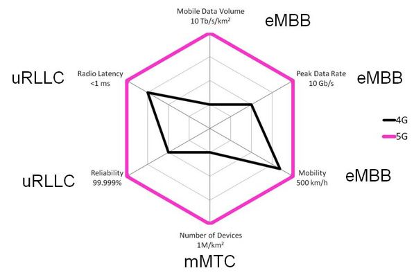
1. Enhanced Mobile Broadband (eMBB)
2. Ultra Reliable Low Latency Communications (uRLLC)
3. Massive Machine Type Communications (mMTC)
eMBB is the continued evolution of wireless data for mobile networks with
the goal of a 10X improvement in downlink (DL) speeds to mobile devices,
achieving 10 Gb/sec compared with 1Gb/sec for 4G LTE services.
uRLLC is a new type of wireless communications service that supports
low latency applications of 1M per km2) for
Smart X applications.
5G is essentially a 10x+ increase in all technical parameters compared
with existing 4G technology today.
5G INFRASTRUCTURE ANALYSIS | 10INTRODUCTION: WHAT IS 5G?
EXHIBIT 3: COMPARISON OF 4G VS. 5G TECHNICAL SPECIFICATIONS
As with prior generation wireless network architecture upgrades, true standalone (SA) 5G
will require a new core network as well as a new radio access network (RAN). We show the
most likely immediately migration path, NSA Option 3a, which allows a mobile operator to
build out a new 5G RAN while utilizing the existing 4G core network. This will save costs for
network operators in the short-term, while allowing initial deployment of 5G network services.
Ultimately, we believe mobile networks will evolve to a SA Option 1/2 architecture where there
are two distinct and separate mobile networks, layered on top of each other. To fully utilize
the uRLLC and mMTC technologies of 5G, a separate core network must be built. In the
short term non-standalone 5G will remain the predominant version of 5G deployment
around the world.
11 | 5G INFRASTRUCTURE ANALYSISEXHIBIT 4: 5G NETWORK EVOLUTION, NSA OPTION 3A VS. SA OPTION 1/2
CORE CORE
NETWORK NETWORK
The other significant change in the network architecture is in the RAN portion of the mobile
network. The 4G evolved node B (eNB) performs the networking Layer 1-2 L1-L3 baseband
processing functions, transport, and operations & maintenance functions. The 5G next generation
node B (gNB) is split into two logical and physical blocks, gNB-DU (5G distributed unit) and gNB-CU
(5G centralized unit). The distributed unit (DU) performs all of the low latency real time processing
of the radio signals while the central unit (CU) performs all of the non-real time processing of the
radio signals. It is important to note that in a first generation 5G mobile network, the vast majority
of mobile operators are implementing a NSA network architecture where all of the traditional eNB
functions are performed by the gNB. The CU-DU split of the gNB will likely occur when the 5G
network transitions to a SA network architecture.
5G INFRASTRUCTURE ANALYSIS | 12INTRODUCTION: WHAT IS 5G?
EXHIBIT 5: RADIO ACCESS NETWORK ARCHITECTURE, 4G VS. 5G
The final major changes in 5G are the 4G LTE networks are frequency division
radio implementation for the duplex mode, duplex (FDD) centric with China Mobile
frequency bands, channel bandwidth, and Sprint as the two major networks using
and a focus on massive MIMO radio units. the time division duplex (TDD) mode. 5G NR
networks will be TDD centric for all frequency
Current 4G LTE frequency bands operate bands in the mid-band and high band
at frequenciesEXHIBIT 6: 5G RU VS. MIMO ORDER VS. FREQUENCY BAND
THE EXISTING WIRELESS NETWORK EQUIPMENT SUPPLIERS
FOR 4G LTE NETWORKS ARE ALSO THE SAME VENDORS FOR
5G NR NETWORKS. THESE ARE:
• China Information and Communication Technologies Group Corporation (CICT)
• Telefonaktiebolaget LM Ericsson
• Huawei Technologies Co., Ltd.
• Nokia Corporation
• Samsung Networks
• ZTE Corporation
Due to the emergence of the O-RAN Alliance, there is a new group of potential
wireless equipment and software suppliers for 5G NR networks that will comply
with the open specifications that the alliance is developing. The twenty-two mobile
operator members of the O-RAN Alliance include the major operators in the United
States, South Korea, Japan, India, China, and Europe. While the O-RAN Alliance is
driving towards a software defined networking focus that would rely on “white- box”
hardware integration, these O-RAN vendors will have to rely on the same standard
network architectures, hardware design blocs, and semiconductor components as
the existing incumbents.
5G INFRASTRUCTURE ANALYSIS | 145G VENDOR NEUTRAL
FUNCTIONAL
REFERENCE
ARCHITECTURES
20 | 5G INFRASTRUCTURE ANALYSIS | SIA CONFIDENTIALTHIS SECTION IDENTIFIES 5G WIRELESS EQUIPMENT
VENDOR NEUTRAL FUNCTIONAL REFERENCE
ARCHITECTURES FOR THE FOLLOWING SYSTEMS:
1. Baseband Unit (BBU)
2. Remote Radio Unit (RRU)
3. Active Antenna Unit (AAU)/Antenna Radio System (ARS)
This functional reference was developed by analyzing each of
the vendor design-bloc choices for the above three systems, then
aggregating design similarities into a “vendor-neutral” model.
WE CLASSIFY A WIRELESS EQUIPMENT VENDOR
AS ONE OF THE FOLLOWING COMPANIES:
1. CICT (China)
2. Ericsson (Sweden)
3. Huawei Technologies (China)
4. Nokia Networks (Finland)
5. Samsung Networks (South Korea)
6. ZTE Corporation (China)
5G INFRASTRUCTURE ANALYSIS | 165G VENDOR NEUTRAL FUNCTIONAL
REFERENCE ARCHITECTURES
BASEBAND UNIT (BBU)
Each baseband unit vendor has a slightly
different system architecture for their
respective solutions, yet still retain many
inherent similarities in order to meet 3GPP
5G standards compliance.
CICT
CICT (China Information and Communications Technology Group Corporation)
is a result of a state merger between FiberHome Telecommunications Technologies
Co., Ltd. (also known as Wuhan Hongxin Communication Technologies Co., Ltd.)
and Datang Mobile Communications Equipment Co., Ltd. in mid-2018 during the
U.S. export ban on ZTE Corporation.
The company uses a typically 8 slot 19” wide 2 rack unit (2U) chassis system for
its 5G BBU. One of the slots is reserved for up to two power supplies while another
is for the transport card, leaving up to six slots for baseband processing.
EXHIBIT 7: CICT 5G BBU
17 | 5G INFRASTRUCTURE ANALYSISERICSSON
Ericsson is the only baseband unit vendor that does not use a upgradeable chassis solution
for its baseband unit. The unit is fixed in terms of hardware capability and ports for backhaul
as well as Fronthaul. The Ericsson 5G BBU is a 19” wide 0.75U height chassis.
EXHIBIT 8: ERICSSON 5G BASEBAND 6630
HUAWEI TECHNOLOGIES CO., LTD.
Similar to CICT, Huawei uses an 8 slot 19” wide 2 rack unit (2U) chassis system for
its 5G BBU. Two of the slots are reserved for backhaul transport cards, leaving up
to six slots for baseband processing.
EXHIBIT 9: HUAWEI 5G BBU5900
NOKIA NETWORKS
Nokia Networks uses a larger 8 slot 19” wide 3U height chassis for its 5G BBU. Two
slots are reserved for the power supply/transport functions, leaving six slots available
for baseband processing.
EXHIBIT 10: NOKIA 5G AIRSCALE BBU
5G INFRASTRUCTURE ANALYSIS | 185G VENDOR NEUTRAL FUNCTIONAL
REFERENCE ARCHITECTURES
SAMSUNG NETWORKS
Samsung Networks also uses a 19” wide 2U height chassis for its 5G BBU but the chassis
only supports four cards, three radios and one transport. We believe that a special high
capacity variant of this solution specific for the South Korean market is between 4-5U
in height supporting up to five radio cards instead of the standard three radio cards.
EXHIBIT 11: SAMSUNG 5G BBU
ZTE CORPORATION
Similar to CICT and Huawei, ZTE uses an 8 slot 19” wide 2 rack unit (2U) chassis system for its
5G BBU. One of the slots is reserved for the power supply while another is for the transport card,
leaving up to six slots for baseband processing.
EXHIBIT 12: ZTE 5G V9200 BBU
The reference architecture that we have chosen to use is representative of
a multi-slot 5G BBU chassis solution where multiple baseband processing cards may be used
within a single chassis. The reference architecture refers to the combination of one baseband
processing card and one transport/timing card.
For architectures that use more than one baseband processing card within the
BBU chassis, the major types of semiconductor integrated circuits (ICs) that
would be duplicated on the additional baseband processing cards would be the
following:
• L1 DSP/ASIC • DDR4 SDRAM • sRIO Switch/ASIC • eCPRI FPGA/ASIC
Additionally, there would be power management and power conversion ICs as well as timing
and logic ICs.
19 | 5G INFRASTRUCTURE ANALYSIS5G VENDOR NEUTRAL FUNCTIONAL
REFERENCE ARCHITECTURES
REMOTE RADIO
UNIT (RRU)
We believe that the primary configuration
for 5G NR TDD RRUs will be 8T8R for all mid-
band 5G NR frequencies (2500-4500MHz).
While we acknowledge that many countries
will also use low-band frequencies
(600-700MHz) in FDD mode for 5G NR, we
believe that the RRU configuration will be
4T4R.
The 8T8R RRUs will be high power using 20W-40W per RF carrier with
a total system RF power of 160-320W. The 8T8R RRU is connected to a separate
passive sectorized antenna panel via nine RF coaxial jumper cables.
THE RRU SYSTEM CAN BE DIVIDED INTO THREE
MAIN SUBSYSTEMS:
1. CPRI Fronthaul + L1 Baseband Processing
2. Digital IF/Analog RF Radio Transceiver
3. Filter
20 | 5G INFRASTRUCTURE ANALYSISEXHIBIT 13: ERICSSON RADIO EXHIBIT 14: NOKIA
8823 3.5GHZ 8T8R RRU NETWORKS 8T8R RRU
EXHIBIT 15: HUAWEI EXHIBIT 16: SAMSUNG
RRU5258 3.5GHZ 8T8R RRU NETWORKS 3.5GHZ 8T8R RRU
EXHIBIT 17: ZTE ZXSDR
R8998 3.5GHZ 8T8R RRU
Sources: Ericsson, Nokia, Huawei, Samsung, ZTE 5G INFRASTRUCTURE ANALYSIS | 215G VENDOR NEUTRAL FUNCTIONAL
REFERENCE ARCHITECTURES
ACTIVE ANTENNA UNIT
(AAU)/ANTENNA RADIO
SYSTEM (ARS)
The primary radio units for 5G NR networks
using mid-band frequencies (2500-4500MHz)
will be configured as a massive MIMO type of
active antenna unit (AAU) or antenna radio
system (ARS). The typical radio transceiver
configurations will be 32T32R or 64T64T with
average RF power levels varying from 100W
up to 320W.
The xTxR massive MIMO configuration of the radio transceiver implies 32 or
64 radio transceivers where x=32 or x=64. A typically 64T64R massive MIMO
antenna system is configured in a 16H4V antenna dipole array with 8 columns
(H) and 12 rows (V) with 2 polarizations (+45/-45). This is typically designated
in the following manner and is shown in Exhibit 23 below:
8(H) x 12 (V) x 2
Each radio transceiver drives three (3) antenna elements on the vertical
plane and one (1) antenna element on the horizontal plane. The typical radio
transceiver to antenna element ratio is a 1:3 in a 64T64R massive MIMO
system for the wireless industry. We define a antenna dipole as formed
by two antenna elements.
22 | 5G INFRASTRUCTURE ANALYSIS5G VENDOR NEUTRAL FUNCTIONAL
REFERENCE ARCHITECTURES
THE AAU SYSTEM CAN BE DIVIDED INTO THREE MAIN SUBSYSTEMS:
1. eCPRI Fronthaul + L1 Baseband Processing
2. Digital IF/Analog RF Radio Transceiver
3. Filter/Antenna
EXHIBIT 18: AAU EXAMPLES BY VENDOR
Source: Ericsson, Huawei, Nokia, Samsung Networks, ZTE Corporation
23 | 5G INFRASTRUCTURE ANALYSISASIC VS. STANDARD
MERCHANT ICs
38 | 5G INFRASTRUCTURE ANALYSIS | SIA CONFIDENTIALBBU
The exhibit below illustrates where the focus for application specific integrated
circuit (ASIC) development has been within the baseband unit. Given the very
high costs of ASIC development, initial prototype equipment is usually designed
around the use of field programmable gate array (FPGA) products to allow for
flexibility as system design parameters and specifications shift during the product
development cycle.
EXHIBIT 19: BBU ASIC VS. MERCHANT IC
ACROSS FUNCTIONAL PRODUCT FAMILIES
Memory
Switches
Fronthaul Optical L1-L3 Baseband SDRAM Clock Gen/Dist Power
FPGA sRIO Power Conversion
Modules Processing Flash Std Logic Management
10GE
EEPROM
ASIC
Merchant
Additionally, given the high costs for design engineers, as well as CAPEX costs
associated with wafer mask sets on leading foundry process nodes, the decision
to go down the ASIC route carries a very high financial and strategic risk. We
believe that the majority of baseband unit designs for 5G use ASICs from the
various wireless equipment suppliers for the L1-L3 baseband processing functions
within the BBU. We also believe that the high speed switching function is also
migrating towards an ASIC solution from merchant solutions.
5G INFRASTRUCTURE ANALYSIS | 25ASIC VS. STANDARD MERCHANT ICs
A key decision factor for choosing to develop an ASIC solution is performance
optimization. While merchant solutions may allow for specific functions to be performed,
they are developed and brought to market for generic use cases and typically do not
factor in specific software functionality support at the hardware level. The development
of an ASIC solution allows an equipment vendor to tailor the level of software required
and hardware required to achieve maximum performance of the system.
WE ARE AWARE OF ASIC SOLUTIONS AT THE
FOLLOWING WIRELESS EQUIPMENT SUPPLIERS
FOR THEIR BBU ARCHITECTURES:
• Ericsson
• Huawei Technologies (using HiSilicon)
• Nokia Networks
• Samsung Networks
• ZTE
AAU/RRU
FOR THE AAU AND RRU SYSTEMS, WE NOTE THAT THE FOCUS
FOR ASIC DEVELOPMENT HAS BEEN ON DIGITAL FRONT END
FUNCTIONS INCLUDING:
• Digital Up Conversion (DUC)
• Digital Down Conversion (DDC)
• Digital Pre Distortion (DPD)
• Beamforming
All of these functions can be supported with FPGAs, however we are seeing a migration
within AAU system designs to focus ASIC development on the antenna beamforming function.
We are also seeing a migration for some equipment vendors to ASIC development for the
common public radio interface (CPRI) and evolved common public radio interface (eCPRI)
fiber optic links that connect the AAU/RRU to the BBU. This remains uncommon as it is simply
much easier to use an FPGA to perform this function. We are also seeing “ASIC” or custom
development for the antenna arrays, as this non semiconductor function is critical for
the AAU performance.
26 | 5G INFRASTRUCTURE ANALYSISThe DUC, DDC, and DPD functions within the radio system can be supported with FPGAs.
We have not seen internally developed RF IC solutions for any of the wireless equipment
vendors that address the transmit (Tx) and receive (Rx) functions of the radio system.
EXHIBIT 20: AAU/RRU ASIC VS. MERCHANT IC
ACROSS FUNCTIONAL PRODUCT FAMILIES
Digital Front
Fronthaul Optical Analog Clock Gen/Dist Power Isolator RF Filter
FPGA End Power Conversion
Modules Front End Std Logic Management Circulator Multiplexer
Beamforming
CPRI/eCPRI A/D Converters
RF SoC Power Amplifiers
Fronthaul D/A Converters
Low Noise
Amplifiers
ASIC
RF Switches
Merchant
WE ARE AWARE OF ASIC SOLUTIONS AT THE
FOLLOWING WIRELESS EQUIPMENT SUPPLIERS
FOR THEIR AAU/RRU ARCHITECTURES:
• Ericsson
• Huawei Technologies (using HiSilicon)
• Nokia Networks
• ZTE
5G INFRASTRUCTURE ANALYSIS | 27SEMICONDUCTOR IC
FUNCTIONAL FAMILIES/
SUPPLIERS
42 | 5G INFRASTRUCTURE ANALYSIS | SIA CONFIDENTIALWE HAVE IDENTIFIED THE FOLLOWING
SEMICONDUCTOR IC PRODUCT FUNCTION FAMLIES FOR
THE 5G BBU REFERENCE ARCHITECTURE:
• Fronthaul Optical SFP/SFP+/QSFP Module
• Field Programmable Gate Array (FPGA)
• L1-L3 Baseband/Network Processor
• Switch, sRIO, PCIe, and Ethernet
• GE PHY Transceivers
• Memory, SDRAM and Flash
• Clock Generation/Distribution
• Standard Logic
• Power Management
• Power Conversion, AC-DC, DC-DC
EXHIBIT 21: SEMICONDUCTOR IC FUNCTIONAL FAMILIES
FOR 5G BBU SYSTEMS
Fronthaul sRIO/ AC-DC
L1-3 Clock Power DC-DC
Optical FPGA Ethernet Memory
Modules
Processing Gen/Dist Mgmt Power
Switch Conversion
GE PHY Standard
Transceivers Logic
WE HAVE IDENTIFIED THE FOLLOWING SEMICONDUCTOR IC
PRODUCT FUNCTION FAMILIES FOR THE 5G RRU AND AAU
REFERENCE ARCHITECTURES:
• Fronthaul Optical SFP/SFP+/QSFP Module
• Field Programmable Gate Array (FPGA)
• RF SoC
• Digital Front End
• Analog Front End
• Tx Gain Blocks, Driver Amplifiers, Power Amplifiers
• Rx Low Noise Amplifiers
• RF Switches
• Clock Generation/Distribution
• Power Management
• Power Conversion, AC-DC, DC-DC
5G INFRASTRUCTURE ANALYSIS | 29SEMICONDUCTOR IC FUNCTIONAL FAMILIES/SUPPLIERS
NON-SEMICONDUCTOR FUNCTIONAL PRODUCT FAMILIES
WITHIN THE RRU AND AAU INCLUDE:
• Isolator/Circulator • RF Filter • Antenna Array
EXHIBIT 22: SEMICONDUCTOR IC FUNCTIONAL
FAMILIES FOR 5G RRU/AAU SYSTEMS
Fronthaul Digital Analog AC-DC
Clock Power DC-DC
Optical FPGA Front Front
Modules Gen/Dist Mgmt Power
End End Conversion
Rx
LNA
RF SoC RF
Switch
Tx
Power
Amplifier
EXHIBIT 23: NON SEMICONDUCTOR
FUNCTIONAL FAMILIES FOR 5G
RRU/AAU SYSTEMS
RF
Isolator Antenna
Filter
Circulator Multiplexer
Array
30 | 5G INFRASTRUCTURE ANALYSIS5G INFRASTRUCTURE ANALYSIS | 31
102 | 5G INFRASTRUCTURE ANALYSIS | SIA CONFIDENTIAL
You can also read