SL-PLUS MIA Stem Surgical Technique for the Minimally Invasive Anterolateral Approach
←
→
Page content transcription
If your browser does not render page correctly, please read the page content below
Joint action improves mobility.

                        ®
SL-PLUS MIA
Stem
Surgical Technique for the Minimally Invasive Anterolateral Approach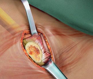
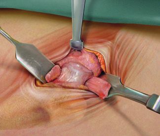
Table of contents

1 Indications                                                        3

2 Contraindications                                                  3

3 Preoperative Planning                                              4

4 Surgical Technique                                                 5

5 Postoperative Treatment                                           16

6 Explanation of the SL-PLUS® MIA Stem                              16

7 Implants                                                          17

8 Instrumentation                                                   18

9 Sterilization                                                     22

The surgical technique was developed and written by Prof. Pflüger
1. Indications

Femora of almost all morphologies can be treated with the SL-PLUS® MIA prosthesis. However,
in some femora with extreme curvatures (e.g. after angulation osteotomies), corrective oste-
otomy should be considered before proceeding with prosthesis insertion. Indications include:

 Advanced wear of the hip joint due to degenerative, posttraumatic or rheumatoid
  arthritis
 Fracture or avascular necrosis of the femoral head
 Condition of the hip joint following previous operations (e.g. osteosynthesis, joint
  reconstruction, arthrodesis, hemiarthroplasty, or total hip prosthesis)

2. Contraindications

 Acute or chronic infections (local or systemic)
 Diseases of the muscular, nervous, or vascular systems that seriously involve the operative
  extremity
 Femora with structural defects or poor bone quality affecting the stability of the
  prosthesis
 Any concomitant disease which may endanger the implant’s function
 Revision THR in the presence of extensive bone defects

                                                                                                3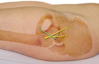
3. Preoperative Planning

    Preoperative planning is recommended to properly choose the size and orientation of the pros-
    thesis. The offset and neck length achieved with the SL-PLUS® MIA prosthesis are determined by
    overlaying X-ray templates (enlarged by 15%) on plain radiographs (AP and axial views).

                                             To determine the appropriate entrypoint for access
                                             of instruments to the medullary canal, it is recom-
                                             mended that the surgeon draw the femoral shaft axis
                                             on the AP radiograph and extend it proximally. This
                                  x
                                             line indicates how far laterally it is necessary to place
                                             the box chisel to open up the canal. This entry point
                                             is easy to locate during surgery.

                                             It is also helpful to define the position of the SL-PLUS®
                                             MIA stem within the canal. This is defined by the
                                             distance from the shoulder of the stem to the greater
                                             and lesser trochanters, and can serve as an additional
                                             intraoperative check of correct stem placement.

                                             For implantation of an SL-PLUS® MIA stem, both the
                                             basic SL-PLUS® instrument case (No. 110450) and the
                                             appropriate SL-PLUS® MIA instrument set are required.

4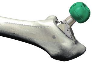
4. Surgical Technique
Note
This technique was developed by Professor Dr. G. Pflüger and his colleagues at the Evangelisches
Krankenhaus in Vienna for the anterolateral, minimally invasive approach performed in the su-
pine position.
Users of other (minimally invasive) approaches are requested to also consult the following op-
erative instructions: posterolateral approach (Lit. No. 1426); anterior approach (Lit. No. 1494).
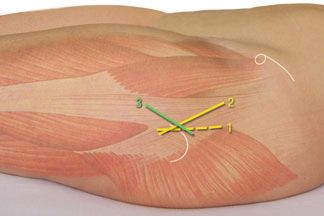
Skin incision
Previous clinical experience has shown that the
SL-PLUS® MIA stem may be successfully implanted
via several skin incisions, including:
1) A longitudinal incision along the anterior edge of
the greater trochanter, extending from 2⁄3 proxi-
mally to 1⁄3 distally to the tip of the trochanter
(Line 1).
2) An oblique incision extending from the anterior
edge of the greater trochanter in the direction of
the anterior superior iliac spine (Line 2).
3) A reverse oblique incision approximating the inter-
trochanteric line (Line 3).
The fascial incision extends from the upper edge of
the tip of the trochanter in the direction of the an-
terior superior iliac spine. Dorsal incision of the ilio-
tibial band is optionally possible.
5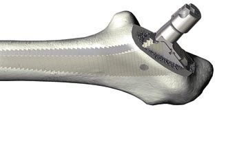
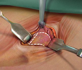
Capsular incision and dissection
After blunt lateral entry between the tensor fasciae
latae and gluteus medius/minimus, the raspatory is
used to dissect along the femoral neck.
Sharp lateral retractors and a blunt medial Hohmann
retractor are used during the surgical exposure. The
arc of the rectus tendon is visualized, underpinned,
incised, and released from its capsule.
The femoral neck is exposed via an H-shaped incision
of the joint capsule, consisting of:
A longitudinal incision, placed as far medially as
possible, and extending from the acetabular
margin to the intertrochanteric line and
a proximal transverse incision of the acetabular
labrum, extending around the acetabular margin
from approximately the nine o’clock to the three
o’clock position and
a distal transverse incision distal extending along
the intertrochanteric line.
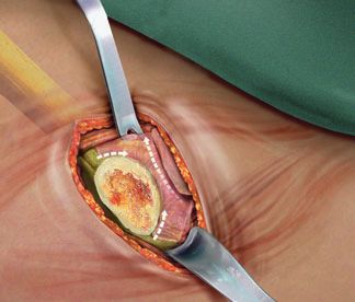
After the wing-like opening of the joint capsule, addi-
tional dissection of the capsule can be performed by
extending the distal incision in the direction of the
lesser trochanter and the proximal incision medially
and/or laterally.
Two blunt Hohmann retractors are positioned intra-
articularly. Problematic osteophytes on the acetabular
rim are removed.
The technique used for the neck resection depends on
the patient (coxa vara/valga) and is selected by the
surgeon (single-incision or double-incision technique).
6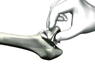
Capsule release
In order to facilitate alignment of the cup, an addi-
tional release of the posterior capsule is performed
with the leg in the “Figure 4” position.

The knee of the operative leg is flexed, allowing it to
be placed under the extended contralateral leg. In this
position, the operative hip is placed in approx. 30°– 40°
of adduction and 90° external rotation.

The proximal femur is mobilized with two hooks: one
placed lateral to the trochanter and the other placed
on the medial side of the neck of the femur.

Capsule releases have to be carried out in the direc-
tion of the lesser trochanter and the trochanteric fossa
to the trochanteric tip. Additional capsular release can
also be carried out on the caudal rim of the acetab-
ulum.

Preparation of the femur for stem insertion
The leg is hyperextended and adducted approx.
30°– 40°, and placed in 90° of external rotation, with
the operative leg positioned under the opposite leg,
in the “Figure 4” position.

In very muscular or obese patients, patients with a
valgus femoral neck, or in cases where the proximal         Inferior Gemellus m.
femur sits deep to the skin surface, further release of       Obturatorius internus m.
the posterior capsule or release of the piriformis ten-
don may be necessary to allow adequate mobiliza-                Superior Gemellus m.
tion of the femur prior to preparation of the implan-            Pirifomis m.
tation site.

                                                                                     7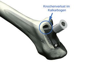
Entry into the medullary cavity
    With the lower thigh kept in a horizontal position, the
    box chisel is placed close to the posterior cortex at the
    resection level. The box chisel should be introduced
    along the femoral axis and a small square block of
    bone is removed. If the box chisel is not used to clear
    hard bone from the osteotomy site, fracture of the
    trochanter may occur during rasp insertion.

    Driving the box chisel below the level of the resected
    bony surface should also be avoided.

    The MIA curved rasp facilitates opening of the diaph-
    yseal medullary cavity.

    Further opening of the diaphyseal medullary cavity
    and probing of the diaphysis with corresponding awl
    is to be recommended.

8
Optional: Use of the pilot rasp
The MIA guide rasps are used to make neutral align-
ment of the rasp easier to achieve, thereby pre-
venting varus positioning of the implant. The MIA
guide rasp should be introduced into the canal in the
desired degree of anteversion, matching the target
rotation of the stem.
The rasp depth can be controlled using the line Markings of the
markings on the shaft. These markings correspond implant shoulder
to the position of the shoulder for each stem size.
During insertion of the MIA guide rasp, care should
be taken to restrict its depth of insertion to one or
two sizes higher than the shoulder position of the
planned implant.
When placing the rasp onto the slap hammer or the
reciprocating driver (“woodpecker”), please ensure
that the side marked “MEDIAL” is indeed oriented
medially. If the medial and lateral sides are inadvert-
ently reversed, the rasp handle may impinge on the
medial aspect of the greater trochanter, preventing
neutral alignment.
For correct stem alignment, the rasp must be seated
in alignment with the canal axis. Please note that
any deviation of the rasp from this axis may lead to
varus positioning of the final implant during stem
insertion.
After the MIA guide rasp has been introduced to the
desired depth, the detachable rasps are used to create
an implantation site of the correct size and alignment
for the femoral implant. This procedure is described
below.
9The rasp cuts longitudinal grooves within the femoral
cortex. The goal of canal preparation is to make the
area of contact between the prosthesis and the cor-
tex as large as possible. By gradually extending the
depth of rasping within the medullary cavity, the area
of contact increases, along with the resistance to
advancement of the rasp in the canal. Once the rasp
is fully engaged within cortical bone, the pitch of the
hammer blows increases and traces of pale cortical
bone appear within the cutting teeth along the
corner edges. To ensure correct sizing of the stem it
is critical that the surgeon establishes the expected
size of implant through preoperative planning prior
to the surgical procedure.
The initial rasp must be size 01 when preparing the
canal for implants of size 4 or smaller. For larger
implants (size 5 or greater), the surgeon may start
with a rasp of size 1.
At the start of the rasping process, the rasp must not
Bone loss in be inserted below the level of the estimated final
calcar arch
position of the implant. It is extremely important to
understand that the femoral osteotomy has no
relationship to the final position. There is a tendency
for surgeons to implant the starting smaller size
rasps too deeply into the femur. This will result in an
excessive enlargement of the implantation site and
lead to gaps around the medial aspect of the final
implant position.
10The subsequent rasp is introduced into the cavity
along a slightly arc-shaped path until resistance is
felt. The rasp is then driven laterally and distally into
the femur with the help of a manual slaphammer or
a power-driven rasping machine. This process is re-
peated with sequential rasp sizes until the final rasp
is seated at an acceptable depth and further up-
sizing is not possible. When using the double offset
adapters (Art. No. 600923/600924), care should be
taken to select the instruments corresponding to the
side of the operative extremity.
Because the first rasp determines the position of all
subsequent rasps, proper orientation of the first rasp
is necessary to ensure correct positioning of the fem-
oral stem.
Attention should be paid to the anteversion and
varus/valgus alignment of the rasping machine with
respect to the femoral axis. Insertion of the rasps or
the stem in a varus inclination increases the risk of
perforation and fracture of the lateral cortex of the
femur.
11Rasping is carried out using the slap hammer or the
rasping machine. The weight of these instruments
helps to ensure the longitudinal alignment of the
rasp within the femur. It is important that a lateral
force is continuously applied to the rasping machine
to ensure that the rasp moves in line with the axis of
the canal and does not seat in a varus position.
Unlike the SL-PLUS® stem, the SL-PLUS® MIA rasp
does not enter and exit the canal along the femoral
axis, but rather along a curved arc.
The shoulder of the detachable rasp corresponds in
height to the shoulder of the implant, and its depth
below the tip of the trochanter should approximate
the corresponding measurement made during pre-
operative planning.
In rare situations, the prosthesis size determined
intraoperatively is in disagreement with the size de-
rived from preoperative templating. If this difference
is two sizes or more, the rasp may not have reached
the necessary depth because of incorrect angulation
or the presence of an obstacle within the canal. In
such cases, the implanted prosthesis is too small to
provide stable long-term fixation. In these situations,
intraoperative fluoroscopy or an intraoperative radio-
graph should be obtained to evaluate the obstruc-
tion.
The offset adapter is removed from the detachable
rasp.
12The modular neck is attached to the detachable rasp
manually.
The trial ball head can be attached to the modular
neck in advance or in situ.
In each case, there is a standard modular neck for
the detachable rasps of sizes 01– 0, 1– 6 and 7–12.
The “lateral” modular necks are available to suit the
detachable rasps of sizes 1– 6 and 7–12.
Care should be taken that the modular neck is cor-
rectly seated on matching surface of the detachable
rasp and engages properly.
The joint is repositioned and leg length, soft-tissue tension, and range of motion are checked by the surgeon.
During the initial operations, it is recommended that the surgeon obtain AP and lateral intraoperative radio-
graphs to verify the size and position of the rasp within the femur.
If necessary, the trial ball head and/or the modular neck (standard or lateral) should be changed until a
satisfactory result is achieved.
The modular neck can be uncoupled either by hand or with a Kocher clamp from the detachable rasp.
The offset adapter is linked with the detachable rasp. The detachable rasp is removed from the canal using
the slap hammer or “woodpecker.” Removal of the rasp, as with its introduction, must be performed along
a curved arc to minimize disturbance of the bone bed and to avoid fractures of any overhanging bone in the
trochanteric region.
13Implantation of the stem
The correct size SL-PLUS® MIA stem is introduced
manually as deep as possible into the canal, and is
then seated with the impactor, using appropriately
measured strokes to minimize the risk of fracture of
the femur.
Pressing the stem in solely by hand is inadequate.
During impact, the protective cover remains posi-
tioned on the cone.
Once the stem is firmly seated, attempts to drive it
further down the canal or to adjust its alignment
within the femur cannot be performed without
fracturing the bone.
Before repositioning the original ball head, the tapered
trunnion is carefully cleaned by hand.
The ball head is then attached to the trunnion with
a slight turning motion and permanently fixed with
a blow delivered with the plastic hammer.
14Metal objects must never be used to deliver impact to
prosthetic heads. If a metal hammer is used, a plastic
coupling must be used to protect the head from direct
contact with the hammer.
Pressing the prosthetic head onto the trunnion solely
by hand provides inadequate fixation.
Each femoral stem has a standard 12/14 trunnion to
allow coupling with ceramic or metal heads supplied
by Plus Orthopedics AG.
Wound closure
Reposition and check joint tension and mobility
on all sides
Insert Redondrains
Closure of the surgical wound
Place the leg in slight abduction and internal
rotation in a foam-padded splint
155. Postoperative Treatment
Postoperative rehabilitation should be completed in accordance with each hospital’s own practices.
The SL-PLUS® MIA stem, similar to the SL-PLUS® stem, is immediately capable of bearing weight.
The definitive osseointegration does not occur until 3 months postoperatively.
®
6. Explanation of the SL-PLUS MIA Stem
The SL-PLUS® MIA stem can be removed using the
extraction screw M6 (Art. No. 110249). If this causes
difficulties, the extraction screw M8 (Art. No. 110911)
and an extractor block are available.
167. Implants
SL-PLUS® MIA standard stem
Art. No. Size Length (L)
11000163 01 128 mm
11000164 0 132 mm
11000165 1 137 mm
11000166 2 141 mm
11000167 3 146 mm
11000168 4 150 mm
11000169 5 154 mm
11000170 6 159 mm
11000171 7 163 mm
11000172 8 168 mm
11000173 9 173 mm
11000174 10 178 mm
11000175 11 183 mm
11000176 12 189 mm
SL-PLUS® MIA lateralized stem
Art. No. Size Length (L)
11000177 1 137 mm
11000178 2 141 mm
11000179 3 146 mm
11000180 4 150 mm
11000181 5 154 mm
11000182 6 159 mm
11000183 7 163 mm
11000184 8 168 mm
11000185 9 173 mm
11000186 10 178 mm
11000187 11 183 mm
11000188 12 189 mm
* undergoing clinical evaluation
SL-PLUS® is a trademark of Plus Orthopedics AG, Switzerland, registered in Switzerland and other selected countries.
178. Instrumentation
SL-PLUS® MIA Set. No. 0943030
Art. No. Description Size
110450 Case Basic Instruments
110901 Slap hammer
110902 Extractor block
110911 Extraction screw M8
110249 Extraction screw M6
110242 Head Impactor
21000143 Trial ball head 28/14 S
21000144 Trial ball head 28/14 M
21000145 Trial ball head 28/14 L
21000146 Trial ball head 28/14 XL
21000147 Trial ball head 28/14 XXL
21000148 Trial ball head 32/14 S
21000149 Trial ball head 32/14 M
21000150 Trial ball head 32/14 L
21000151 Trial ball head 32/14 XL
21000152 Trial ball head 32/14 XXL
21000153 Trial ball head 36/14 S
21000154 Trial ball head 36/14 M
21000155 Trial ball head 36/14 L
21000156 Trial ball head 36/14 XL
21000141 Trial ball head 22/14 M
21000142 Trial ball head 22/14 L
600621 MIA Stem Impactor
21000138 MIA curved rasp
41000029 SL-PLUS® Box chisel
Optional:
41000030 MIA Guide rasp
Optional for users of the SL-PLUS® MIA Stem and SL-PLUS® stem:
110500 Adapter for trial rasp
1810
OPTIONAL
8 1
4
3
6
11 OPTIONAL
9
5
2
7
19SL-PLUS® MIA Set. No. 0943030
Art. No. Description Size
990019 Cover
600930 MIA Instrument case for SL
21000123 MIA Detachable rasp 01
21000124 MIA Detachable rasp 0
21000125 MIA Detachable rasp 1
21000126 MIA Detachable rasp 2
21000127 MIA Detachable rasp 3
21000128 MIA Detachable rasp 4
21000129 MIA Detachable rasp 5
21000130 MIA Detachable rasp 6
21000131 MIA Detachable rasp 7
21000132 MIA Detachable rasp 8
21000133 MIA Detachable rasp 9
21000134 MIA Detachable rasp 10
21000135 MIA Detachable rasp 11*
21000136 MIA Detachable rasp 12*
21000253 MIA modular neck for detachable rasp 01– 0 Std.
21000254 MIA modular neck for detachable rasp 1– 6 Std.
21000255 MIA modular neck for detachable rasp 7–12 Std.
21000256 MIA modular neck for detachable rasp 1– 6 Lat.
21000257 MIA modular neck for detachable rasp 7–12 Lat.
41000029 SL-MIA box chisel
SYS251374 Trochanter retractor
600922 MIA Offset Adapter 10 mm
600923 MIA Double Offset Adapter left 17 mm left 13 mm
600924 MIA Double Offset Adapter right 17 mm right 13 mm
Optional for users of the SL-PLUS® MIA Stem and SL-PLUS® stem:
600620 MIS Offset box chisel
Optional:
600920 MIA Offset adapter 25 mm
600921 MIA Offset adapter 40 mm
* Optional and must be ordered separately
204
OPTIONAL
5
1
9
3 2
7
6
8
219. Sterilization
Implants
All the implants described in this Surgical Technique are sterile when they are delivered by the
manufacturer. Resterilization is not allowed.
Instruments
System components and instruments are not sterile when they are delivered. Before use, they
must be cleaned by the usual methods in accordance with internal hospital regulations and
sterilized in an autoclave in accordance with the legal regulations and guidelines applicable in the
relevant country. (For detailed information please refer to leaflet Lit. No. 1363.)
The correct settings are given in the instructions for use issued by the autoclave manufacturer.
Instrument manufacturers and dealers accept no responsibility for sterilization of products by the
customer.
2223
Notes

24
Belgium
                                Plus Orthopedics Belgium Sprl
                                Rue du Bosquet, 2, P.I Nivelles Sud, 1400 – Nivelles
                                Phone +32 67 879 500, Fax +32 67 646 640
                                China
                                Plus Orthopedics (Beijing) Co., Ltd.
                                7th Floor, Modern Palace, No. 20 Daluyuan
                                Dongsanhuan Nanlu, Chaoyang District
                                Beijing 100022, P.R. China
                                Phone +86 10 8778 3322, Fax +86 10 6776 3622
                                Germany
                                Plus Orthopedics GmbH
                                Mainstrasse 2, 45768 Marl
                                Phone +49 2365 91 81 0, Fax +49 2365 91 81 10
                                France
                                Plus Orthopedics France Sarl
                                14, Villa des Fleurs, 92400 Courbevoie
                                Phone +33 1 49 97 04 60, Fax +33 1 47 68 09 36
                                Greece
                                Plus Orthopedics Hellas S.A.
                                Kleanthous Street 8, GR 16346 Ilioupoli, Athina
                                Phone +30 2 10 99 13 190, Fax +30 2 10 99 31 809
Distribution                    United Kingdom
                                Plus Orthopedics (UK) Limited
                                Barbury House, Stonehill Green, Westlea, Swindon SN5 7HB
                                Phone +44 1793 719 222, Fax +44 1793 619 222
                                Italy
                                Plus Orthopedics Italy Srl
                                Via Archimede 76, 20041 Agrate Brianza (MI)
                                Phone +39 039 657 921, Fax +39 039 657 92 35
Sales Partners in:              Japan
                                Plus Orthopedics K.K.
Australia                       Tomigaya-Ogawa Bldg. 2-41-12, Tomigaya
Baltic countries (EE, LT, LV)   Shibuya-ku, Tokyo 151-0063
Belarus                         Phone +81 3 3467 5581, Fax +81 3 3467 5582
Bosnia
                                The Netherlands
Brazil
                                Plus Orthopedics Netherlands BV
Bulgaria
                                Postbus 785, 2700 AT Zoetermeer
India
                                Phone +31 793 41 7071, Fax +31 793 42 5601
Indonesia
Iran                            Austria
Croatia                         Plus Orthopedics GmbH
Kuwait                          Grenzgasse 38a, 2340 Mödling
Malaysia                        Phone +43 2236/48 407-0, Fax +43 2236/41 149-4
Norway
Russia                          Switzerland
Slovakia                        Plus Orthopedics Schweiz AG
Slovenia                        Erlenstrasse 4a, 6343 Rotkreuz
South Africa                    Phone +41 41 798 41 11, Fax +41 41 798 41 00
South Korea                     Spain
Thailand                        Plus Orthopedics España S.A.
Czech Republic                  c/Islas Aleutianas n 4, 28035 Madrid
Turkey                          Phone +34 91 376 86 20, Fax +34 91 376 86 21
                                USA
                                Plus Orthopedics USA, Inc.
                                10188 Telesis Court, San Diego, CA 92121
                                Phone +1 858 550 3800, Fax +1 858 457 56 18

                                Switzerland
                                Plus Orthopedics AG (Manufacturer)
                                Erlenstrasse 4a, 6343 Rotkreuz
                                Phone +41 41 798 41 11, Fax +41 41 798 41 00

                                info@plusorthopedics.com
                                www.plusorthopedics.com

Technical changes reserved      Lit. No. 1524-e Ed. 07/07 500 Ex. 07/07                    0123
You can also read