Optimization and Application of Support Scheme for Tunnel with High In-situ Stress in Ningchan
←
→
Page content transcription
If your browser does not render page correctly, please read the page content below
E3S Web of Conferences 248, 03004 (2021)                                                                https://doi.org/10.1051/e3sconf/202124803004
CAES 2021

           Optimization and Application of Support Scheme for Tunnel with
           High In-situ Stress in Ningchan
           ZHANG Xueqiang1*
           1Qinghai   Communications Construction Management Co, Ltd., Xining, Qinghai, 810003, China

                         Abstract. Based on the national highway 569 Mandala Datong highway Ningchan tunnel, the study on the
                         optimization design of high ground stress tunnel support parameters is carried out. The results show that the
                         single-layer primary support with I20b as the main support framework cannot control the large deformation
                         of high ground stress tunnel, mainly manifested as arch frame failure and concrete spalling; adopting
                         "double-layer initial support" can control large deformation to a certain extent; increasing the stiffness of
                         inner layer support can reduce the "double-layer" to a certain extent The results show that the cumulative
                         deformation of "support", but cannot significantly shorten the deformation stability period; appropriately
                         increasing the reserved deformation between the inner and outer layers of the initial support has the best
                         supporting effect, the cumulative deformation is small, and the deformation stability period is shortened.
                         The research results provide a basis for similar high stress tunnel support measures.

       1        Introduction                                                   that the effect of "strong support" was better. In China,
                                                                               Wushaoling Tunnel on Lanzhou-Xinjiang Railway [11]
       The stability of tunnel rock masses is controlled by                    and Muzhailing Tunnel on Lanzhou-Chongqing Railway
       various structural planes formed by the ground stress on                [12-14] have successfully passed through the high
       the site and the interaction between ground stress field                ground stress areas by means of "multi-layer support"
       and rock masses. Ground stress is not only an important                 and "pilot tunnel stress release". Zheng Xixi et al., after
       factor that determines the regional stability, but also a               analyzing the surface deformation law and influencing
       fundamental force for deformation and failure of                        factors caused by tunnel construction, put forward
       underground engineering. It is a prerequisite for                       targeted design schemes and control measures based on
       determining the properties of engineering rock mass                     project features [15].
       mechanics, analyzing the stability of surrounding rock                       However, up to now, no support measure suitable for
       and realizing scientific excavation design and decision-                tunnels with high ground stress is clearly given in either
       making of geotechnical engineering [1,2]. Due to the                    relevant codes or practice summary. Disasters caused by
       poor self-stability of surrounding rocks, tunnel                        high ground stress during tunnel construction process are
       construction in high ground stress areas is prone to                    still common, so it is necessary to further summarize and
       serious engineering problems such as rock burst, large                  refine the effective support measures to enrich the
       deformation, intrusion, collapse or lining damage [3],                  sample database.
       which will not only worsen the engineering geological                        In this paper, relying on Ningchan high ground stress
       conditions of tunnel rock masses, but also cause direct                 tunnel, the experimental study of support parameters is
       harms to structures. Therefore, the selection of                        carried out on the basis of high ground stress tests. By
       reasonable support measures has become a challenge in                   means of field test and theoretical analysis, the support
       engineering construction.                                               effects of different support methods are monitored and
           Up to now, scholars at home and abroad have done a                  measured by optimizing support parameters, and
       lot of research work on the support measures of tunnels                 reasonable support parameters for expressway tunnels
       with high ground stress [4-6]. Wang Daoyuan et al. [7-8]                crossing high ground stress areas are put forward to
       carried out field test researches on the control method of              provide successful cases for similar projects..
       large deformation of high ground stress tunnel, and
       summed up the support concept of "flexible support
       before rigid support, deformation before stabilization,                 2     Project overview
       and combination of both". Wang Bo et al. [9] think that
                                                                               Ningchan Tunnel is located in Xianmi Township,
       "yielding support" is more suitable for tunnels with high
                                                                               Menyuan County in the section from Ningchan Pass to
       ground stress than "strong support" and "layered
                                                                               Ketu on National Highway 569 Mandela-Datong
       support". On the other hand, Cui Guangyao et al. [10]
                                                                               Highway. It is a two-way twin-bore four-lane tunnel of
       conducted the field test at Zhongyi Tunnel, and believe
                                                                               Class I highway. The starting/ending mileage peg
           *
               Corresponding author: 413436993@qq.com

  © The Authors, published by EDP Sciences. This is an open access article distributed under the terms of the Creative Commons Attribution License 4.0
  (http://creativecommons.org/licenses/by/4.0/).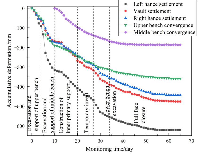
E3S Web of Conferences 248, 03004 (2021) https://doi.org/10.1051/e3sconf/202124803004
CAES 2021
numbers of the left and right tunnels are Table 1 and Table 2 are the vertical borehole
ZK37+140~ZK43+164 and YK37+190~YK43+133 hydrofracturing and horizontal borehole hydrofracturing
respectively, and the excavation area is 114m2. When results, respectively. By using the borehole
the left line of the tunnel was excavated to hydrofracturing stress test method and rock uniaxial
ZK41+123~ZK41+063, the surrounding rock conditions compression test, the obtained results at the tunnel site
changed. According to the exposure of the tunnel face, it was that the average value of the maximum horizontal
was mainly strongly weathered carbonaceous slate, with principal stress was 18.38MPa, the average value of the
blastopelitic texture, layered and massive structure, minimum horizontal principal stress was 11.2MPa and
extremely developed joint fissures, and the rock masses the dominant direction of the maximum horizontal
were broken and loose, with the attrition crushing principal stress was NW64º. The average value of
surface accounting for more than 75%. Fig. 1 shows the saturated compressive strength of rock, Rc, was
vault surrounding rock of Tunnel Face ZK41+088 of the 13.04MPa, and the strength-stress ratio of rock,
left line. RC/σmax, was 0.71, which was less than 4. According to
the Standard for Engineering Classification of Rock
Mass (GB/T 50218-2014), it was an extremely high
ground stress area.
Fig. 1. Vault Surrounding Rock of Tunnel Face ZK41+088 of
Left Line.
Table 1. Vertical Borehole Hydrofracturing Results.
Fracture Reopening Closing Maximum Minimum
Head Pore Direction of
pressure pressure pressure horizontal horizontal
pressure pressure maximum
Depth principal principal
' ' horizontal
/m Pb
' Pr Ps PH P0 principal
stress H stress h
/MPa /MPa /MPa /MPa stress
/MPa /MPa /MPa
29.3 8.92 8.25 7.66 0.29 0.29 15.02 7.95
31.3 14.26 10.54 9.42 0.31 0.31 18.03 9.73
33.3 15.25 11.28 9.92 0.33 0.33 18.81 10.25 NW63°
35.3 12.68 10.74 9.78 0.35 0.35 18.95 10.13
37.3 15.00 13.39 10.66 0.37 0.37 18.96 11.03 NW65°
39.3 12.40 10.61 10.00 0.39 0.39 19.78 10.39
Table 2. Horizontal Borehole Hydrofracturing Results
Fracture Reopening Closing Maximum Minimum
pressure pressure pressure principal stress principal stress Direction of
Depth
/m Pb
'
Pr
'
Ps
'
H h maximum
principal stress
/MPa /MPa /MPa /MPa /MPa
33 16.15 11.58 9.14 15.84 9.14
35 17.81 12.63 9.06 14.55 9.06
37 21.90 17.52 11.39 16.65 11.39
39 24.28 19.05 12.01 16.98 12.01
and tests were carried out in Section
3 Support parameter optimization ZK41+120~ZK40+988.
After adopting I18 steel arch reinforcement as per the
Combined with the geological conditions and aiming at original design scheme, the deformation was controlled,
the high ground stress characteristics of Ningchan but the accumulative deformation was large. Therefore,
Tunnel, the tunnel support parameters were optimized, starting from the two aspects of "increasing support
stiffness" and "appropriately increasing reserved
2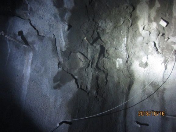
E3S Web of Conferences 248, 03004 (2021)                                                             https://doi.org/10.1051/e3sconf/202124803004
CAES 2021

       deformation", an experimental study for the optimization             section ZK41+063~ZK41+033, S2 support was adopted
       of support parameters were conducted on a total of four              in test section ZK41+033~ZK41+003 (See Fig. 2 for the
       test sections.                                                       parameters of S2 support), and S3 support was adopted
           S0 support was adopted in test section                           in test section ZK41+003~ZK40+988. See Table 3 for
       ZK41+120~ZK41+075, S1 support was adopted in test                    specific design parameters.

                                                                                                          Φ42×4 grouted spiles, L=4.5m

            Φ42×4 grouted spiles, L=4.5m                                                                  Φ8 reinforcing mesh with a
                                                                                                          spacing of 20×20 (single layer)
            Spacing 60×120 (longitudinal
            × circumferential), in blossom-                                                               I 22b arch frame (longitudinal
            shape arrangement                                                                             spacing 60)

                                                                                                          28cm-thick C25 shotcrete

                                                                                                          Reserved deformation 50cm

                                                                                                          Φ8 reinforcing mesh with a
                                                                                                          spacing of 20×20 (single layer)
                                                                                                          I 20b arch frame (longitudinal
                                                                                                          spacing 60)

                                                                                                          26cm-thick C25 shotcrete

                                                                                                          Reserved deformation 20cm

                                                                                                          350g/m2 non-woven fabrics

                                                                                                          Waterproof board

                                                                                                          65cm-thick C30 reinforced
                                                                                                          concrete

                                                          Fig. 2. S3 Support Parameters

                                                Table 3. Support Parameter Design of Test Sections

          Support
                                                                      Support parameters
           type
                       Forepoling: Adopt Φ42×4 grouted spiles. L=4.5m, with a circumferential spacing of 35cm, a longitudinal spacing of
                       60cm, an setting angle of 8~12° and an overlapping length of 249cm
                       Primary support: Φ8 reinforcing mesh, I20b steel arch frame (layout spacing 50cm). Spray C25 concrete with a
             S0
                       thickness of 26cm. Use 8 groups of Φ42× 4 grouted spiles (L=5m) in the feet-lock bolts of each arch frame (2 in
                       each group)
                       Secondary lining: Adopt 50cm-thick C40 reinforced concrete
                       Forepoling: Φ42 grouted spiles, L=4.5m.
                       System anchor bolt: Φ42 grouted spiles, L=4.5m.
                       Outer primary support: Φ8 reinforcing mesh, I22b arch frame (layout spacing 60cm). Spray 28cm-thick C25
                       concrete
             S1
                       Reserved deformation: 30cm
                       Inner primary support: Φ8 reinforcing mesh, I18 arch frame (layout spacing 60cm). Spray 28cm-thick C25 concrete
                       Reserved deformation: 25cm
                       Secondary lining: 65cm-thick C30 reinforced concrete
                       Forepoling: Φ42 grouted spiles, L=4.5m.
                       System anchor bolt: Φ42 grouted spiles, L=4.5m.
                       Outer primary support: Φ8 reinforcing mesh, I22b arch frame (layout spacing 60cm). Spray 28cm-thick C25
                       concrete
             S2
                       Reserved deformation: 30cm
                       Inner primary support: Φ8 reinforcing mesh, I20 arch frame (layout spacing 60cm). Spray 28cm-thick C25 concrete
                       Reserved deformation: 25cm
                       Secondary lining: 65cm-thick C30 reinforced concrete

                                                                        3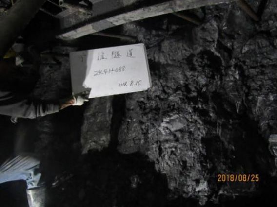
E3S Web of Conferences 248, 03004 (2021)                                                                      https://doi.org/10.1051/e3sconf/202124803004
CAES 2021

                    Forepoling: Φ42 grouted spiles, L=4.5m.
                    System anchor bolt: Φ42 grouted spiles, L=4.5m.
                    Outer primary support: Φ8 reinforcing mesh, I22b arch frame (layout spacing 60cm). Spray 28cm-thick C25
                    concrete
            S3
                    Reserved deformation: 50cm
                    Inner primary support: Φ8 reinforcing mesh, I20 arch frame (layout spacing 60cm). Spray 28cm-thick C25 concrete
                    Reserved deformation: 20cm
                    Secondary lining: 65cm-thick C30 reinforced concrete

                                                                                         (1)     Vault settlement value monitoring;
                                                                                         (2)     Sidewall convergence value monitoring.
       4 Layout of monitoring points in test
       sections
                                                                                      4.2 Layout of monitoring points in test
                                                                                      sections
       4.1 Monitoring contents in the tests
                                                                                      In order to measure the development law of vault
       In order to master the deformation development of                              settlement and horizontal convergence after tunnel
       Ningchan high ground stress tunnel after excavation and                        excavation, a total of five monitoring points were
       evaluate the advantages and disadvantages of the                               arranged on vault, left spandrel, right spandrel and left
       existing support schemes in time, the field monitoring                         sidewall. The detailed layout is shown in Fig. 2.
       mainly covered the following two aspects:

                                                                                          Monitoring point - Vault

                                                                                                            Monitoring
                                                                                                            point - Spandrel
                                                              Tunnel centerline

                                                                                                                     Monitoring
                                                                                                                     point - Sidewall

                                                    Fig. 3. Layout of Monitoring Points

                                                                                      deformation (as shown in Fig. 4) and shotcrete spalling
       4.3 Analysis of test results                                                   (as shown in Fig. 5).
       1. Analysis on effect of S0 support
           The primary support structure with I20b as the main
       skeleton adopted in the original design scheme has poor
       effect. According to the monitoring data of Section
       ZK41+120~ZK41+075 in the left line, the vault
       settlement and horizontal convergence values were large
       after the completion of the primary support, and there
       was no sign of tending towards stability. The maximum
       vault settlement reached 6cm/d, and the maximum
       horizontal convergence reached 11cm/d. Under the
       action of high ground stress, the primary support
       structure could no longer resist the surrounding rock
                                                                                                 Fig. 4 Severe Arch Frame Deformation
       pressure, and some sections even had serious arch frame

                                                                                  4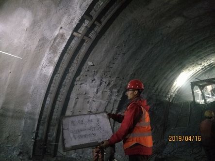
E3S Web of Conferences 248, 03004 (2021) https://doi.org/10.1051/e3sconf/202124803004
CAES 2021
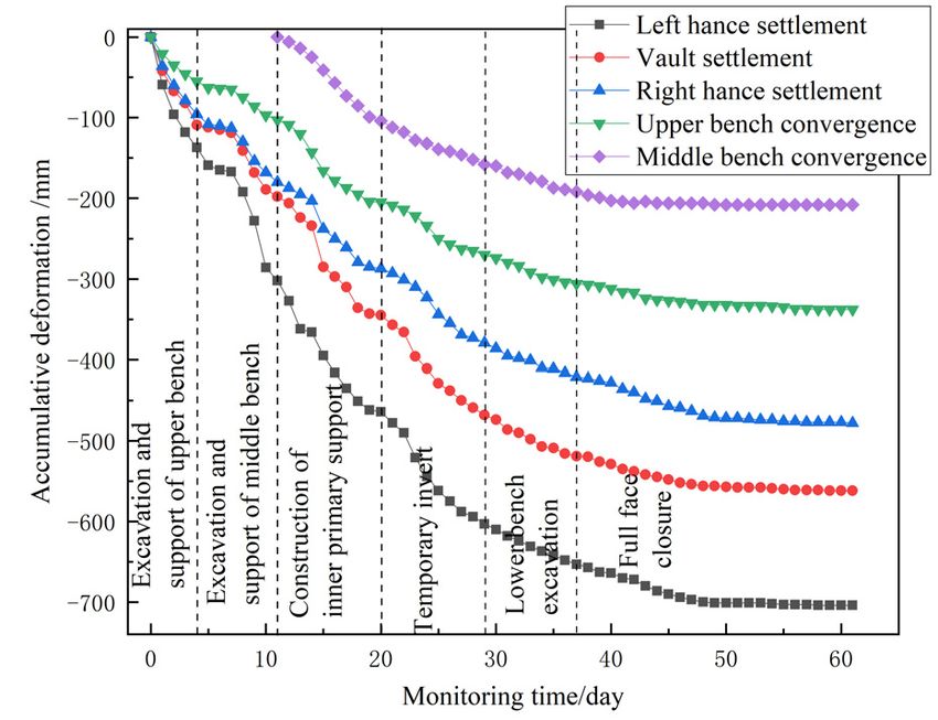
Fig. 7 is the convergence duration curve of Section
ZK41+038 when adopting S1 double-layer primary
support. The figure shows: (1) Compared with the
settlement values of vault and right spandrel, the
settlement value of left spandrel was relatively larger,
that is, the location of the maximum settlement value
was basically consistent with the direction of the
maximum principal stress (NW64°); (2) The arch
settlement can be divided into three stages: the rapid
development stage before the completion of the inner
primary support, with a settlement accounting for 61%;
the slow-down stage from the completion of the inner
Fig. 5 Spalling of Sprayed Concrete
primary support to the full face closure, with a settlement
accounting for 31%; the slow deformation stage after the
In order to prevent the further development of
full face closure, with a settlement accounting for 8%.
deformation and ensure the safety of the primary support
That is, after the inner support was constructed, the arch
of the tunnel, radial grouting reinforcement with I18
settlement was still very large, and the settlement was
steel arch reinforcement and Φ42 spile was conducted
close to 40%. In the next optimization, the stiffness of
for the primary support of this section. After the
the inner primary support can be appropriately increased.
completion of the "double-layer primary support"
construction, although the accumulative deformation is
large, the rate of vault settlement and horizontal
convergence of surrounding rock was controlled to a
certain extent, and the vault settlement and convergence
tended to be stabilized. That is to say, the "double-layer
primary support" had a certain control effect on large
deformation of high ground stress tunnel. On this basis,
"double-layer primary support" was determined as the
main support measure in the next stage, and double-layer
primary support test was carried out in Section
ZK41+063~ZK40+988 of the left line to optimize the
support parameters.
2. Analysis on effect of S1 support
About 55 days after S1 support was adopted in
Section ZK41+063~ZK41+033 (See Fig. 6 for the result
after the construction of the inner primary support), the
arch settlement and horizontal convergence tended to be Fig. 7 Convergence Duration Curve of Section ZK41+038
stabilized, the arch frame and shotcrete were intact, and
there was no steel frame damage or concrete falling off. 3. Analysis on effect of S2 lining support
Compared with single-layer primary support, double- On the basis of S1 support, this section mainly
layer primary support can obviously control large improved the stiffness of inner primary support, and
deformation in high ground stress. The final value of adjusted the arch frame from I18 to I20b. After S2
horizontal convergence was between 208mm and support was adopted in Section ZK41+033~ZK41+003,
338mm, but the final value of arch settlement was the arch settlement and horizontal convergence tended to
between 478mm and 704mm, which had exceeded the be stabilized in about 55 days. The final value of arch
reserved deformation, so the support parameters need to settlement was between 443mm and 622mm, which was
be further optimized. reduced by 7%~12%. The final value of peripheral
convergence was between 187mm and 359mm, and the
lower bench convergence value decreased, but the upper
bench convergence increased. Obviously, the maximum
deformation (the settlement value of the left hance was
622mm) had exceeded the reserved deformation of 55cm.
Although increasing the stiffness of the inner primary
support brought some reduction in the cumulative
deformation, the supporting effect was still poor.
Fig. 8 is the convergence duration curve of Section
ZK41+006. It can be seen that after the inner primary
support was completed, the arch structure with higher
stiffness could not control the deformation completely,
Fig. 6. Inner Primary Support of S1 Support Completed and the surrounding rock pressure at this time was still
very high, and its release took a long time. Although
adopting the optimization measure of “stiff resisting" can
5
E3S Web of Conferences 248, 03004 (2021)                                                        https://doi.org/10.1051/e3sconf/202124803004
CAES 2021

       reduce the accumulative settlement to a certain extent, it
       still cannot achieve the expected supporting effect.

                                                                             Fig. 9 Increasing Reserved Deformation of S3 Support

          Fig. 8 Convergence Duration Curve of Section ZK41+006

           4. Analysis on effect of S3 lining support
           On the basis of S2 support, this section mainly
       increased the reserved deformation: the total reserved
       deformation was adjusted to 70cm, and the reserved
       deformation of the inner and outer primary supports was
       adjusted from 30cm to 50cm. The increased reserved
       deformation of S3 support was shown in Fig. 9. After S3
       support was adopted in Section ZK41+003~ZK40+988,
       the supporting effect was good: the arch settlement and
       horizontal convergence had tended to be stabilized in
                                                                          Fig. 10. Convergence Duration Curve of Section ZK40+991
       about 40 days, the final value of arch settlement was
       between 411mm and 525mm, and the final value of                       Fig. 10 is the convergence duration curve of Section
       horizontal convergence was between 73mm and 214mm,                ZK40+991. Due to the enough deformation set between
       both of which were less than the reserved deformation of          the inner and outer primary supports, the surrounding
       70cm.                                                             rock pressure was released enough. After the inner
                                                                         support was completed, the settlement of S3 support was
                                                                         relatively small, and it tended to converge in a short time
                                                                             5. Comparative Analysis of Supporting Effects
                                                Table 4. Comparison of Supporting Effects

                                              Maximum                                       Reserved deformation
          Support     Optimization                                  Maximum cumulative                               Convergence
                                            accumulative                                     of inner and outer
           type        measures                                      convergence value                                  time
                                           settlement value                                        layers
                       Single-layer                                                                                       No
            S0                                    -                          -                        -
                     primary support                                                                                  convergence
                      Double-layer                                                                                     About 55
            S1                                 704mm                     338mm                      30cm
                     primary support                                                                                    days
                      Increasing the                                                                                   About 55
            S2                                 622mm                     359mm                      30cm
                         stiffness                                                                                      days
                      Increasing the
                                                                                                                       About 40
            S3           reserved              525mm                     214mm                      50cm
                                                                                                                        days
                       deformation

           The original design scheme adopted single-layer               support with higher stiffness, but because the reserved
       primary support, which could not effectively control              deformation between the inner and outer supports was
       large deformation. After adopting S1 double-layer                 small, the surrounding rock pressure could not be
       primary support, although the large deformation was               released before the construction of the inner support,
       controlled, the accumulative deformation still exceeded           resulting in the subsequent accumulative deformation
       the reserved deformation, and its deformation                     still exceeding the reserved deformation, and the
       convergence period was long. The deformation could be             convergence period was still very long. Setting reserved
       reduced to a certain extent by adopting the inner primary         deformation between the inner and outer primary

                                                                     6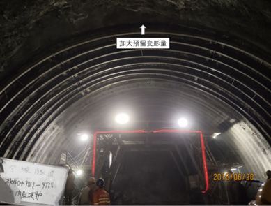
E3S Web of Conferences 248, 03004 (2021)                                                        https://doi.org/10.1051/e3sconf/202124803004
CAES 2021

       supports could make the surrounding rock pressure                 5.    Yin Liu,Brian Moran. Large deformation near a
       released, and the accumulative deformation was small                    crack tip in a fiber-reinforced neo-Hookean sheet[J].
       and the convergence period was short.                                   Journal of the Mechanics and Physics of Solids,
                                                                               2020,143.
       5     Conclusions                                                 6.    Ummer Amin Sheikh,Azher Jameel. Elasto-plastic
                                                                               large deformation analysis of bi-material
       Through the optimization study on the support                           components by FEM[J]. Materials Today:
       parameters in the test sections of Ningchan high ground                 Proceedings, 2020,26(Pt 2).
       stress tunnel, the following conclusions are obtained             7.    Cao Xiao ping, Wei Fei peng, Wang Bo, Liu Zi
       after comprehensive analysis:                                           yang. Experimental study on reasonable support
           (1)    The single-layer supporting structure with                   scheme of soft rock tunnel with high in-situ stress
       I20b as the main skeleton cannot cope with the high                     [J]. Journal of Railway Engineering, 2018, 35(07):
       ground stress of Ningchan Tunnel, which is mainly                       65-71+102.
       manifested by arch deformation, shotcrete spalling and            8.    Wang Dao yuan, Liu jia, Zhang Chuo etc. High in-
       excessive and non-convergent accumulative deformation;                  situ stress fractured buried tunnel with large
           (2)    Double-layer primary support can effectively                 deformation control method for field test study [J].
       deal with the non-convergent deformation problem of                     Chinese Journal of Geotechnical Engineering: 1-10.
       Ningchan high ground stress tunnel. After adopting
       double-layer primary support, the maximum deformation             9.    Wang Bo, Guo Xin xin, He Chuan, Wu De xing.
       position of Ningchan Tunnel is consistent with the                      Analysis on Characteristics and Development Trend
       direction of the maximum ground stress, and its                         of High-in-situ Stress Tunnel Support Technology in
       deformation development presents three stages: the rapid                China [J]. Modern Tunneling Technology, 2018,
       development stage before the completion of the inner                    55(05): 1-10.
       primary support, the slow-down stage from the                     10.   Cui Guang yao, Wang Xue lai, Wang Ming sheng.
       completion of the inner primary support to the full face                Field test study on large deformation control in
       closure, and the gradual stabilization stage after the full             fracture zone of deep buried tunnel with high in-situ
       face closure;                                                           stress [J]. Chinese Journal of Geotechnical
           (3)    Increasing the stiffness of inner primary                    Engineering, 2019, 41(07): 1354-1360.
       support can reduce the deformation to a certain extent,           11.   Li Guo liang, Zhu Yong quan. Large deformation
       but properly increasing the reserved deformation of                     control technology of weak surrounding rock with
       inner and outer primary support and giving the                          high in-situ stress in Wushaoling tunnel [J]. Journal
       surrounding rock pressure an appropriate release time                   of Railway Engineering, 2008(03): 54-59.
       will produce better supporting effect, which is                   12.   Li Yan zong, Zhao Shuang. Construction Scheme
       manifested in the reduction of accumulative deformation                 and Deformation Analysis of Multi-layer Support
       and shortening of convergence period.                                   Structure for a High In-situ Stress Soft Rock Tunnel
                                                                               [J]. Modern Tunneling Technology, 2019, 56(03):
       Acknowledgments                                                         161-165.
                                                                         13.   Liu Zhao wei, Wang Ming sheng, Fang Jun bo.
       This work is jointly supported by the Science and                       Experimental study on supporting system of tunnel
       Technology Project of Transportation Department of                      with high in-situ stress and large deformation [J].
       Qinghai Province (No. 2020-01).                                         Chinese Journal of Civil Engineering, 2010, 43(05):
                                                                               111-116.
       References                                                        14.   Liu Gao, Zhang Fei yu, Li Xin zhao et al. Analysis
                                                                               of Large Deformation Characteristics and
       1.   Chen Jun quan. The treatment of large deformation                  Mechanism of Muzhailing Tunnel [J]. Chinese
            of soft surrounding rock in highway tunnel [J].                    Journal of Rock Mechanics and Engineering,
            Highway Traffic Technology, 2018, 34(05):106-112.                  2005(S2): 5521-5526.
       2.   Technology - Materials Research; Studies from                15.   Zheng Xi xi, Wu Sheng zhong. Study on Ground
            Swinburne University of Technology Provide New                     Deformation Control of Large Span Shallow Buried
            Data on Materials Research (Large Deformation of                   Asymmetric Urban Tunnel with Small Clear
            Corrugated Sandwich Panels Under Three-point                       Distance [J]. Highway Traffic Technology, 2019,
            Bending)[J]. Journal of Technology,2020.                           35(03):94-99..
       3.   Wang Wan ping, Li Jian fei, Xin jiang he, Bie Su
            ping. Analysis of Large Deformation Structure of
            Large Span Flat Extreme Soft Rock Tunnel [J].
            Highway Traffic Technology,2018,34(S1):45-51.
       4.   Cheng Xi. Application of Monitoring and
            Measurement in Treatment of Large Deformation of
            Jiangluling Tunnel [J]. Highway Traffic Technology,
            2016,32(06):115-120.

                                                                     7
You can also read


