Damage tolerance design of transport aircraft
←
→
Page content transcription
If your browser does not render page correctly, please read the page content below
IOP Conference Series: Materials Science and Engineering

PAPER • OPEN ACCESS

Damage tolerance design of transport aircraft
To cite this article: H Vishnu et al 2021 IOP Conf. Ser.: Mater. Sci. Eng. 1091 012065

View the article online for updates and enhancements.

                               This content was downloaded from IP address 46.4.80.155 on 03/05/2021 at 04:54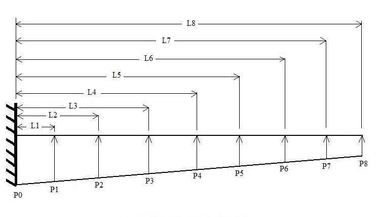
ICIRMCT 2021                                                                                                             IOP Publishing
IOP Conf. Series: Materials Science and Engineering             1091 (2021) 012065            doi:10.1088/1757-899X/1091/1/012065

Damage tolerance design of transport aircraft

                     H Vishnu1 , R Ajith Kumar 1,3 , R Sujith1 , R Suraj1 and K E Girish2

                     1
                         Department of Mechanical Engineering, SCMS School of Engineering and Technology,
                         Kerala, India
                     2
                         Director, Bangalore Aircraft Industries Ltd., Bangalore, India

                     Abstract. In a transport aircraft, there are normally two spars to withstand bending loads. A
                     large part of this bending moment is drawn from the main spar. The main spar in large
                     transport wings is an integrally machined part that is physically connected to the skin and ribs.
                     At some fastener openings, the mechanical fastening contributes t o extreme tension
                     concentration where a fatigue crack can originate. This crack will form first in the flange under
                     service loading and then expand into the spar network. If not detected during service and
                     repaired, this crack growth can lead to catastrophic failure. This investigation aims at
                     examining the main spar's alternate structural design to make it damage tolerant. With one
                     more intermediate flange and at a height of one-third from the bottom flange, the spar
                     construction will be in two separate parts. The bottom flange and web can fail in the case of
                     fatigue cracking, but the top flange, web, and intermediate flange will remain intact and can be
                     designed to bear the requisite load limit design. An approach to finite element modelling and
                     analysis is also used to analyze all forms of spar constriction and test the principle of harm
                     tolerance nature.

1. Introduction
Damage tolerance is a feature of a system that refers to its ability to safely retain faults before they can
be damaged by repair. The approach to engineering design to allow for risk tolerance is based on the
premise that in any system there will be defects and these defects spread with use. In aerospace
engineering, this technique is also used to handle the expansion of structural cracks by applying the
concepts of fracture mechanics.
The analysis of risk tolerance of aerial structural components [1] provides descriptions of the types of
damage that are likely to occur during production and damage caused in operation. Harm resistance is
the ability to withstand fracture for a given period of time from the pre-existing cracks and is an
integral feature of materials whose failure could result in loss of life or property. The second line of
protection against premature fracture is then provided by the integration of structural configurations
and materials that are resistant to sub-critical crack growth and final fracture. “Operational
survivability” was introduced [4] in 1976 similar to previous work. It contained the principles of fail-
safe and hazard tolerance. Aviation regulations for transport aircraft were adopted in 1994, where the
definition of operating survivability was assigned as the primary one. In C-130 aircraft [5], due to the
consequences of hard use, various cracks are occurred. Damage tolerance design greatly lessens the
possibility of such cracks causing a serious accident or requiring excessive down time for emergency
repair. Cracks such as these were contained sufficiently by damage tolerance deign to permit safe
operation until the using command was able to ferry the aircraft to a repair base.

              Content from this work may be used under the terms of the Creative Commons Attribution 3.0 licence. Any further distribution
              of this work must maintain attribution to the author(s) and the title of the work, journal citation and DOI.
Published under licence by IOP Publishing Ltd                          1
ICIRMCT 2021                                                                                       IOP Publishing
IOP Conf. Series: Materials Science and Engineering   1091 (2021) 012065      doi:10.1088/1757-899X/1091/1/012065

Under conditions of severe usage, damage can develop and propagate with unexpected rapidity. A
damage tolerant structure, however, greatly increases the chances of damage being detected before it
reaches critical proportions affecting safe operation. Cracking of a spar web is a typical wing damage
mode that may be treated analytically. Damage tolerance is achieved by ascertaining that un-failed
wing structure is capable of redistributing the damaged spar web load without causing propagation of
the damage. Due to fatigue break, numerous catastrophic failures of aircraft systems occurred in the
20th century [2]. In 1948, a Martin-202 aircraft with 40 passengers crashed because of wing failure
caused by a fatigue fracture in a 7075-T6 wing spar joint. In 1948, a Martin-202 aircraft with 40
passengers crashed because of wing failure caused by a fatigue fracture in a 7075-T6 wing spar joint.

2. Problem Definition
The primary aim is to examine the main spar’s alternative structural architecture to make it tolerant of
damage. At a height of 1/3rd from the bottom flange, the spar construction would be in two different
components with one or more intermediate flange. The bottom flange and web can fail in the case of
fatigue cracking, but the top flange, web, and intermediate flange will remain intact and can be
designed to bear the requisite load limit design. In order to analyze all forms of spar construction and
verify the principle of damage tolerance architecture, a finite element modelling and analysis approach
will be employed.

2.1. Geometrical configuration
The required part is modeled in CATIA and the same was imported into NASTRAN for the analysis.
The 3D sketch of the model used for the analysis is shown in the figure 1.

                                       Figure 1. Isometric view of the spar

The material used for the model is an aluminum alloy. The name of the material is AL 2024 T351
alloy. The geometrical specifications of the model is taken as L1 = 500 mm, L2 = 4000 mm, T1 = 2.5
mm, T2 = 5 mm, t1 = 1.5 mm and t2 = 3 mm.

3. Stress analysis of spar
The finite element mesh model consists of quad, tria and bar elements. The total number of elements is
shown in table 1. Also the finite element analysis of spar is shown in figure 2.

                                      Figure 2. Finite element form of spar

                                                         2
ICIRMCT 2021 IOP Publishing
IOP Conf. Series: Materials Science and Engineering 1091 (2021) 012065 doi:10.1088/1757-899X/1091/1/012065
Table 1. Model summary of wing spar
Parameter Value
Grid points 39265
Bar elements 900
Quad elements 10592
Tria elements 56
3.1. Load calculations
The various steps used for calculating the load in spar in discussed in this section. The all up weight is
2500 kgf while the load factor is taken as 3. Therefore the total design load will be 7500 kgf. This load
is distributed on the wings and fuselage as 80% and 20% respectively. Therefore the load on both the
wings of aircraft will be 80% of the total design load (7500 kgf) and that will be equal to 6000 kgf. In
this study, we are concerned with the single wing. Hence the load on a single wing will be half of the
load in both wings and that will be equal to 3000 kgf. Further, the load on front spar will be 75% of
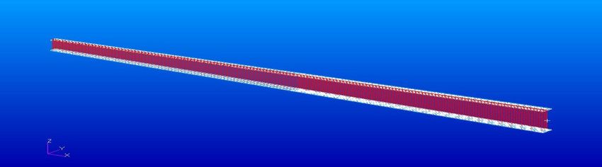
load in each wing and it will be equal to 2250 kgf. This load on the spar is given as distributed load on
the model as shown in figure 3. The load at tip must be found out as shown in figure 4. It was
calculated by momentum balance and was found to be 802.875 kgf.
Figure 3. Load distribution of spar Figure 4. Load calculation at tip
Table 2. Value of load along length
Parameter Load value along length
Length L0=0 L1=562.5 L2=1125 L3=1687.5 L4=2250 L5=2812.5 L6=3375 L7=3937.5 L8=4500
(mm)
Load P0= 438 P1=394 P 2=328 P3=272 P4=227 P5=206 P6=175 P7=119 P8=92
(kgf)
3ICIRMCT 2021 IOP Publishing
IOP Conf. Series: Materials Science and Engineering 1091 (2021) 012065 doi:10.1088/1757-899X/1091/1/012065
4. Evaluation of damage tolerance
For the damage tolerance analysis of the spar, stress intensity factor is to be calculated. The stress
intensity factor is calculated using Modified virtual crack closure integral method (MVCCI). In order
to validate this method, a classical problem was chosen. A rectangular plate with a crack at the center
was taken for the validation purpose. The schematic diagram of this plate is shown in figure 4.
Figure 5. Schematic diagram of rectangular plate with crack at center
The input data for the given problem are P = 2000 kg, 2h = 800 mm, 2b = 400mm and thickness =
2mm. The rectangular plate as shown in the above figure was modelled analysed in the Patran. From
the data obtained from the analysis, using MVCCI method, stress intensity factor was calculated.
These values are compared with experimental proved value. It was found that SIF values obtained
through FEM method is same as the experimentally proved values. Hence this FEM method is
validated and it can be used for SIF calculation of any geometry.
4.1. Procedure for the theoretical calculation of SIF
At right angles, in an infinite plane, to a uniform stress field σ, the stress pressure factor for a through
crack of length 2a is given by
√ (1)
If the crack is centrally positioned on a finite plate of 2b width and 2h height, the stress strength
element has an estimated relationship given by
[ ( ) ] (2)
√
√
where is remotely applied stress, a is half of the crack length and b is half of plate width
4.2. MVCCI method for calculating SIF
In this method, SIF is calculated with the help of data obtained from FEM method. As per this method,
stress intensity factor, K is given by
√ (3)
where G is the strain energy release rate which is given by
(4)
4ICIRMCT 2021 IOP Publishing
IOP Conf. Series: Materials Science and Engineering 1091 (2021) 012065 doi:10.1088/1757-899X/1091/1/012065
where E is the Young’s Modulus, is length of element near the crack tip, is opening node
displacement, F is the force acting at crack tip and t is the thickness of the plate.
The energy dissipated during fracturing per unit of newly generated fracturing surface area is the strain
energy release rate (or energy release rate). For fracture mechanics, this quantity is important because
the energy that must be given to a crack tip for it to expand must be balanced by the amount of energy
dissipated due to the creation of new surfaces and other dissipative processes such as plasticity. Data
needed for calculation of K which is to be obtained from the FEM analysis is shown in the figure 5.
Figure 6. Parameters required for SIF calculation
5. Results and discussions
In the initial sage, the spar was analyzed and the maximum stress occurring region was found out. The
stress values occurred at the corresponding regions is given in the table below. In this case, stress
occurred due to tension is taken into consideration.
Table 3. Maximum shear stress values at each part
Stress
Part
(kg/mm2 )
Top skin -25.8
Top flange -31.4
Bottom skin 7.33
Bottom Flange 19.9
After finding out the maximum shear stress region, using MVCCI method, Stress Intensity Factor was
calculated. The SIF values for each crack length was found out and tabulated in table 4.
Table 4. Values of K for different crack lengths
Parameter Crack length and SIF values
Crack
5 8 9.4 11 12 46
length
SIF 11.661 14.454 15.871 17.203 18.443 48.208
(K)
The variation values of SIF along the crack length is shown in figure 7. It is clear from the graph that
the SIF values are getting higher as the crack length is increased and hence the flange will get failed.
After the complete failure of flange, the crack get initiated through the web and propagate throughout
the spar which result in the failure of the aircraft structure.
5ICIRMCT 2021 IOP Publishing
IOP Conf. Series: Materials Science and Engineering 1091 (2021) 012065 doi:10.1088/1757-899X/1091/1/012065
60
50
Stress Intensity Factor
40
30
20
10
0
0 10 20 30 40 50
Crack Length
Figure 7. Variation of SIF along crack length
In the further step, crack was simulated through the web and SIF was calculated for the different crack
lengths. The variation of SIF for different crack lengths in web along crack length is plotted in figure
8. From the graphical plot it is clear that SIF value keep on increasing which finally results in the
failure of the structure. So the design was further modified.
300
Stress Intensity Factor
250
200
150
100
0 10 20 30 40 50 60 70 80 90 100
Crack Length
Figure 8. Variation of SIF along crack length without flange
So in order to modify the model, an intermediate flange is introduced at a height one-third from the
bottom flange and the same procedure was followed. Here also a graph is plotted to depict the
variation of SIF along the crack length with intermediate flange in figure 9. It can be seen from the
plot that the SIF value got reduced when the crack is approaching near the intermediate flange. So it is
clear that by introducing an intermediate flange, the crack propagation can be arrested to an extent,
hence the wing spar can be made as damage tolerant.
6ICIRMCT 2021 IOP Publishing
IOP Conf. Series: Materials Science and Engineering 1091 (2021) 012065 doi:10.1088/1757-899X/1091/1/012065
250
200
Stress Intensity Factor
150
100
50
0 20 40 60 80 100
Crack Length
Figure 8. Variation of SIF along crack length with intermediate flange
6. Conclusions
In this study the damage tolerance design of transport aircraft is studied. The stress analysis is carried
out using finite element method (FEM). The stress on the bottom skin and bottom flange are obtained
and it was found that stress on bottom flange is greater than that of bottom skin. After doing the finite
element analysis, the Stress Intensity Factor (SIF) was calculated verified using MVCCI method. The
damage tolerance calculation is carried out by finding out the SIF at different crack lengths.
Modifications was done on the model to minimize the damage tolerance and it was found that the
structure will fail in all cases until the use of intermediate flange. The stress analysis and SIF
calculation has been carried out in the presence of intermediate flange. The results with the presence
of intermediate flange show that SIF decreases when the crack get nearer to intermediate flange.
7. References
[1] Kiran R, Sachin R,Hemanth U, Ashok S, Hakeem S A and Narayana K B 2007 Damage
tolerance analysis of aero structural components Tata Consultancy Services
[2] Jaap Schijve 2009 Fatigue damage in aircraft structures, not wanted, but tolerated?’
International Journal of Fatigue vol 31 pp 998–1011
[3] Friedrich G B, Azzedine C and Hans A R 1999 Computational fracture analysis by means of
Virtual Crack Closure Integral Method MECOM99 6th Argentine Congress on
Computational Mechanics, Mendoza
[4] Nesterenko G I, Nesterenko B G 2009 Ensuring structural damage tolerance of Russian aircraft
International Journal of Fatigue vol 31 pp.1054–1061
[5] Shuler W T and Morcock D S 2012 Damage tolerance and logistic transport design J.Aircraft
vol 6 no 5 pp 416–424
[6] Molent L 2010 Fatigue crack growth from flaws in combat aircraft International Journal of
Fatigue vol 32 pp 639-649
[7] Barter S, Molent L, Goldsmith N, Jones R 2005 An experimental evaluation of fatigue crack
growth Engineering Failure Analysis vol 12 pp 99–128
[8] Shuler W T and Morcockj D S 2012 Damage tolerance and logistic transport design Journal of
Aircraft vol 6 no 5 pp 416–424
[9] Castro P M, Tavares S M O, Richter T V , Matos P F P, Moreira P M G P and Silva L F M 2010
Damage tolerance of aircraft panels Revista da Associação Portuguesa de Análise
Experimental de Tensões
7ICIRMCT 2021 IOP Publishing
IOP Conf. Series: Materials Science and Engineering 1091 (2021) 012065 doi:10.1088/1757-899X/1091/1/012065
[10] Grandt F 2011 Damage tolerant design and nondestructive inspection - Keys to aircraft
airworthiness Procedia Engineering vol 17 pp 236–246
[11] Adeel M 2008 Study on damage tolerance behavior of integrally stiffened panel and
conventional stiffened panel World Academy of Science, Engineering and Technology vol 45
pp 1026–1030
[12] David B 1982 Elementary engineering fracture mechanics Martinus Nijhoff Publishers, pp 408–
433
[13] Silva L F M, Gonçalves J P M, Oliveira F M F and de Castro P M S T 2000 Multiple-site
damage in riveted lap-joints: Experimental simulation and finite element prediction,
International Journal of Fatigue, vol 22 pp 319–338
[14] Rans C D, Alderliesten R C and Straznicky P V 2009 Assessing the effects of riveting induced
residual stresses on fatigue crack behaviour in lap joints by means of fractography,
International Journal of Fatigue, vol 31 pp 300–308
[15] Horst P 2006 Widespread fatigue damage–qqqqqqqqAn issue for aging and new aircraft Key
Engineering Materials, vol 324-325 pp 1–8
8You can also read