Myon: Concepts and Design of a Modular Humanoid Robot Which Can Be Reassembled During Runtime
←
→
Page content transcription
If your browser does not render page correctly, please read the page content below
August 18, 2011   13:13                     WSPC - Proceedings Trim Size: 9in x 6in   CLAWAR2011-Hild

                                                                                                        1

                  Myon: Concepts and Design of a Modular Humanoid Robot
                        Which Can Be Reassembled During Runtime
                      Manfred Hild, Torsten Siedel, Christian Benckendorff, Matthias Kubisch,
                                                and Christian Thiele
                                          Neurorobotics Research Laboratory
                                            Humboldt-Universität zu Berlin
                                                 Unter den Linden 6
                                               10099 Berlin, Germany
                            {hild|siedel|benckend|kubisch|thiele}@informatik.hu-berlin.de

                   We describe the design concepts of the modular humanoid robot Myon, which
                   can be disassembled and reassembled during runtime. The body parts are fully
                   autonomous in a threefold sense: they all possess their own energy supply,
                   processing power, and a neural network topology which allows for stand-alone
                   operation of single limbs. The robot has especially been designed for robustness
                   and easy maintenance. It exhibits a combination of an endoskeleton with an
                   exoskeleton, the latter of which can manually be detached without the need for
                   technical equipment. One of the essential parts is a novel flange which firmly
                   connects the body parts mechanically, whilst at the same time relaying the
                   power supply lines and sensorimotor signals. We also address the details of the
                   antagonistic and compliant actuation system which not only protects the gears
                   against high impact forces but also enables biologically inspired joint control.

                   Keywords: Humanoid robot; Modular architecture; Power autonomy; Antago-
                   nistic actuation.

             1. Introduction and Design Concepts
             Humanoid robots are highly complex systems and as such prone to dam-
             ages and malfunctioning. This is especially true if not only an upper torso
             with head and arms is used, but the full body, e.g. to test and analyze sen-
             sorimotor loops for walking motions and stable standing. There are several
             approaches to remedy the situation, depending on the experimental set-
             tings that are planned to be addressed with the humanoid platform. If full
             autonomy is not needed, then energy supply and processing power can be
             placed outside the robot and the bare skeleton can be optimized for maxi-
             mal mechanical robustness. Also, the type of the actuators plays a crucial
             role. Pneumatic-driven humanoid robots can withstand a drop from more
August 18, 2011 13:13 WSPC - Proceedings Trim Size: 9in x 6in CLAWAR2011-Hild
2
Figure 1. The humanoid robot Myon. Left: Schematic diagram of the joints’ positions
and orientations. Right: Image of the functional robot including the exoskeleton shells.
The exoskeleton is a structural element which prevents the inner endoskeleton from
external torsional loads. Furthermore, the electronic components are protected from
mechanical impacts and the user from crushing injuries.
than one meter height onto the ground without any problem, although it
has to be noted, that pneumatic actuators have much longer response times
than electric motors.1 Hence, if the robot needs to be mobile within the ex-
perimental setting then electric actuators and on-board batteries have to
be used. The robot Myon, which is shown in Figure 1, has been designed
for experiments on artificial language evolution2 and therefore needs to be
able to autonomously wander around, recognize and manipulate different
objects, and communicate with other robots. Moreover, the robot is also
to be used as a research platform for biologically inspired behavior control,
using tight sensorimotor loops and antagonistic joint actuation. As recently
stated by Migliore et al.,3 the vast majority of walking robots still loses en-
ergy by ignoring the potential benefit of using passive elastic components
at their joints. On Myon, elastic components could be incorporated in a
very compact way along with the antagonistic actuation system. This notAugust 18, 2011 13:13 WSPC - Proceedings Trim Size: 9in x 6in CLAWAR2011-Hild
3
only opens up the research field of energy-efficient walking behaviors, but
in the first instance protects the gears against high external impact forces.
In the following, we outline the overall system architecture and focus on
the robot’s modularity and the antagonistic actuation system. We addition-
ally address the system’s power autonomy, the compliance of the actuation
system, and the flange design which allows the robot’s body parts to be
detached and re-attached during runtime.
2. Overall Properties
The robot has especially been designed for robustness and easy mainte-
nance. It exhibits a combination of an endoskeleton with an exoskeleton,
the latter of which can manually be detached without the need for technical
equipment. All in all, the robot is 1.25 m tall and weighs 15 kg, including
the shells (see Table 1). It consists of six body parts (head, torso, arms,
and legs) which are fully autonomous in terms of energy supply, process-
ing power, and neural network topology. This way, single body parts can
Table 1. Overview of the robot’s mass, degrees of freedom (DOFs), and num-
ber of actuators. Except for the eye, a single type of actuator is used for all
joints. Joints which need a large amount of torque, e.g. the knee, are driven by
several actuators in parallel.
Module Mass Joint DOFs Actuators
(kg) (number) (number) (type)
Head 1.4 Eye 4 4 Micro servo
Neck 3 3 RX-28
Arm (2x) 1.1 Shoulder 1 1 RX-28
Elbow 1 1 RX-28
Wrist 1 1 RX-28
Gripper (2x) 0.2 Fingers 1 1 RX-28
Torso 2.5 Shoulder (2x) 1 2 RX-28
Waist 1 1 RX-28
Leg (2x) 1 1 RX-28
Leg (2x) 3.0 Hip 2 5 RX-28
Knee 1 3 RX-28
Ankle 2 5 RX-28
Toe 1 – passive
Shells (total) 2.5 – –
Total 15.0 32 48August 18, 2011 13:13 WSPC - Proceedings Trim Size: 9in x 6in CLAWAR2011-Hild
4
be operated stand-alone using the distributed local processing nodes and
special neuro-modules4 as control structures. One of the essential parts is
a novel flange which firmly connects the body parts mechanically, whilst at
the same time relaying the power supply lines and sensorimotor signals.
3. System Architecture
The inner system architecture is shown in Figure 2. Each body part exhibits
an Energy Module built of four Lithium-ion polymer batteries (3.55 Ah at
14.8 V, nominal) and an analog circuit which guarantees lossless energy bal-
ancing between all body parts. They are connected using a multi-core bus,
the so-called Extended Spinal Cord, which transfers energy, sensorimotor
data at a rate of 4.5 MBaud, and a control signal which is used to switch
the robot on and off. Processing is done by 25 distributed processing nodes.
They are called AccelBoard3D, since they also possess a 3-axis acceleration
sensor, despite the Cortex-M3 RISC processor running at 72 MHz. Actua-
tors and additional sensors are connected to each AccelBoard3D. The robot
Myon does not exhibit a central processor, but the head features an Field
Programmable Gate Array (FPGA) for image processing (see BrainModule
in Figure 2).
Head Other BodyParts
Camera WLAN Sensor
RX-28 RX-28
BrainModule AccelBoard3D
RX-28 RX-28
I/O ExtensionBoard I/O
Servo Servo
AccelBoard3D AccelBoard3D
Servo Servo
SC Battery SC Battery
EnergyModule EnergyModule
XSC XSC
Figure 2. System architecture of the robot Myon. Components within each body part
are connected via the so-called Spinal Cord (SC), whereas the body parts are connected
by the Extended Spinal Cord (XSC) which includes several additional lines for energy
transfer as well as a control line for quick shutdown of the robot.August 18, 2011 13:13 WSPC - Proceedings Trim Size: 9in x 6in CLAWAR2011-Hild
5
4. Runtime Modularity
The body parts of the robot Myon can be detached and reattached during
runtime, since every body part is fully autonomous, having its own power
supply, computational power, as well as a special firmware which allows
for hot plugging and respects the topological structure of the underlying
recurrent neural control network. Figure 3 shows the robot’s torso and the
battery pack which can be inserted and removed easily. The flange design
can be seen in Figure 4 in more detail. It consists of two interlocking rings
which guarantee a mechanically firm connection. This is very important,
e.g. for the legs, where large forces have to be transmitted between the
limb and the torso. The electrical connection is placed in the middle of the
flange. It relays the Extended Spinal Cord (XSC) as shown in Figure 2.
Figure 3. Construction of the robot’s torso, exhibiting the flanges for the other body
parts. The torso is made of aluminum and therefore only weighs 2.5 kg including actua-
tors, electronics and batteries. The design of the battery pack allows for easy insertion
and removal using a single hand.August 18, 2011 13:13 WSPC - Proceedings Trim Size: 9in x 6in CLAWAR2011-Hild
6
Figure 4. Detailed view of the novel flange which firmly connects the robot’s body parts
mechanically, whilst at the same time relaying the power supply lines and sensorimotor
signals. The flange can be controlled using a single hand and allows for detachment and
reattachment of body parts during runtime.
5. Power Autonomy
The power autonomy of the robot’s body parts was a crucial design goal,
since it enables stand-alone experiments with single limbs. An example of
such an experiment is the stand up motion of a single leg, as presented
by Hild and Kubisch.5 Also the balance recovery reported by Kubisch et
Battery Pack AccelBoard3D
14.8 V (nom.)
3550 mAh Step Down LDO, 2 x 3.3V
3.9V (TPS 71933-33)
(MAX 1836)
Digital Analog
Energy Module Logic Processing
XSC SC
Power supply mixing LDO, 2 x 3.3V LDO, 2 x 3.3V
using optimal diodes (TPS 71933-33) (TPS 71933-33)
(LTC 4412)
RS-485 Acceleration RS-485 RS-485
Transient (SC) Sensor (DSA) (DSB)
Voltage
Suppressor
Figure 5. Power distribution within the robot. The Extended Spinal Cord (XSC) con-
tains power lines from all body parts, whereas the Spinal Cord (SC) locally provides
power within each body part (also see Figure 2). The SC power is predominantly re-
cruited from the local battery pack, but other body parts can provide additional power
if needed, e.g. during a knee bend. In order to save energy, and also to achieve maximum
robustness against system failures, each AccelBoard3D processing node uses a step down
converter (3.9 V) and six short-circuit-proof, low-drop-out voltage regulators (3.3 V each)
for the different functional parts of the circuit, as indicated.August 18, 2011 13:13 WSPC - Proceedings Trim Size: 9in x 6in CLAWAR2011-Hild
7
al.6 uses only part of the robot, namely the torso with two legs. As the
details of the power distribution reveal (see Figure 5), each body part can
be driven by a mix of local power from the body part’s own battery pack
and the power from all other body parts which may more distant to the
energy-consuming actuators, but which also may be not as exhausted as the
local supply. Depending on the type of full body motion, a single battery
pack is able to power the whole robot for twenty minutes or even longer.
Surely, power can also be supplied via unconnected flanges (if not all body
parts are used) or via an extra connector below the torso’s battery pocket
(see Figure 3).
6. Antagonistic Actuation
The robot exhibits 32 degrees of freedom which are driven by 48 actuators
(see Table 1), i.e., several actuators (all of the type Robotis RX-28) drive the
same joint, allowing for biologically inspired, antagonistic control strategies.
Each actuator is equipped with a torsion spring, as shown in Figure 6. This
spring provides a series elasticity which balances forces between actuators
that drive the same joint. The spring stiffness is chosen so that high impact
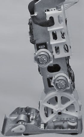
forces are damped enough not to break the actuator’s gear in. Figure 7
shows a close-up of the ankle pitch joint, which is driven by four actuators.
Figure 6. Detailed view of the torsion spring which is connected to each actuator in a
compact way. The spring provides the necessary series elasticity to drive a single joint
with multiple actuators in an antagonistic way. Forces are transmitted via wire ropes
(also see Figure 7) which are clamped by a screw. Additionally, the spring also protects
the actuator’s gear from unforeseen high external impact forces.August 18, 2011 13:13 WSPC - Proceedings Trim Size: 9in x 6in CLAWAR2011-Hild
8
Figure 7. Detail of the ankle joint. Left: Photograph of the foot and leg without ex-
oskeleton shells. Middle and Right: Schematic side views showing the four actuators
(small circles) which drive the ankle pitch joint (big circle) via wire ropes.
7. Summary
We have described the modular humanoid robot Myon, which can be dis-
assembled and reassembled during runtime, since all body parts are fully
autonomous. The robot is robust and easy to maintain due to its exoskele-
ton and special flanges. In addition, Myon exhibits an antagonistic actua-
tion system which enables researchers to study biologically inspired control
strategies.
Bibliography
1. K. Hosoda, Y. Sakaguchi, H. Takayama and T. Takuma, Pneumatic-driven
jumping robot with anthropomorphic muscular skeleton structure, in Au-
tonomous Robots, 2010.
2. L. Steels and M. Spranger, How experience of the body shapes language about
space, in Proc. of the 21st Internat. Joint Conf. on Artifical Intelligence (IJ-
CAI’09), 2009.
3. S. A. Migliore, L. H. Ting and S. P. DeWeerth, Passive joint stiffness in the
hip and knee increases the energy efficiency of leg swinging, in Autonomous
Robots, 2010.
4. M. Hild, Neurodynamische Module zur Bewegungsteuerung autonomer mo-
biler Roboter, in PhD thesis, Humboldt-Universität zu Berlin, 2007.
5. M. Hild and M. Kubisch, Self-Exploration of Autonomous Robots Using
Attractor-Based Behavior Control and ABC-Learning, in Proc. of the 11th
Scandinavian Conf. on Artificial Intelligence, (Trondheim, Norway, 2011).
6. M. Kubisch, C. Benckendorff and M. Hild, Balance Recovery of a Humanoid
Robot Using Cognitive Sensorimotor Loops (CSLs), in Proc. of the 14th In-
ternat. Conf. on Climbing and Walking Robots, (Paris, France, 2011).You can also read