INSTALLATION GUIDE LED STRIP LIGHT, NEON & CHANNEL - Want to see how to install these products? Go to YouTube and type in Nova Flex LED to watch ...
←
→
Page content transcription
If your browser does not render page correctly, please read the page content below
INSTALLATION
GUIDE
LED STRIP LIGHT, NEON & CHANNEL

   Want to see how to install these products?
   Go to YouTube and type in Nova Flex LED to watch our quick installation videos.
ATTENTION: This product should be installed by a professional licensed electrician.
1. TURN POWER OFF AT CIRCUIT BREAKER 7. MOUNT STRIP LIGHT IN CHANNEL
SHOCK HAZARD! Turn power OFF at circuit breaker prior to a. Channel without Clips
installation to avoid serious injury or death. Install channel directly to the surface with the provided
screws. You will need to pre-drill the holes before installation
2. VERIFY PRODUCT IS CORRECT
or use self- tapping screws when installing onto metal.
Pre-light using the wiring diagrams in this guide to ensure Kelvin
temperature (color) is correct. DO NOT connect max runs yet.
b. Channel with Clips
3. DETERMINE LOCATION TO INSTALL Screw clips to the surface at the beginning and end of each
Dry-fit the lights to the desired location BEFORE removing the section and then about every 1.5 ft in between. For certain
adhesive backing (for strip light). Refer to the CONFIGURATION channels, you can utilize the clips to connect channel
GUIDE for a list of products and zone locations. (see diagram).
4. PREP SURFACE PRIOR TO INSTALLING STRIP LIGHT
c. Universal Clips
To ensure lasting bond, use the provided alcohol wipe to prep the
Attach the provided channel clips to the Universal
surface (wall, channel, etc). For slippery surfaces, pre-sand the
Clips. Then install at least four clips for every 2M
area before installing the lights or use the 3M Primer 94.
of channel, to the surface with screws. Snap your
channel into the clips and secure the channel by pinching the
5. MOUNT THE STRIP LIGHT
clips around the channel.
Once fit is confirmed, begin peeling the backing and gently press
the strip light into place, slowly working your way towards the
end. This process will make it easier to handle the strip light, d. Mud-In Channel
especially in longer runs. In channel, center the strip light starting Prep the wall by measuring the channel width and cutting
into the drywall. Then, slide the channel in the wall, with the
1/8” away from the end cap with the hole.
wings resting on the drywall. (Optional: Secure the channel in
NOTE: Adhesive MUST BE REMOVED for proper heat dissipation. place by using screws in the mud-in holes.)Then, mud over the
Do not let the LEDs hang when installing, as this could add stress wings to secure the channel.
to the solder connections.
e. Channel with Magnets & Connectors
IF INSTALLING IN CHANNEL Slide the round magnets into the bottom of the channel. Plan
Skip to step #9 for NEON to place 4 magnets for every 2M of channel. Then simply
place it onto a magnetic surface.
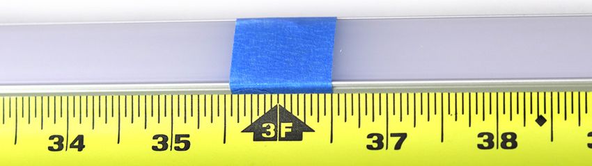
6. CUT THE CHANNEL FOR STRIP LIGHT
To determine the cut length, place the LED strip light beside the To connect channel for longer runs, slide half of the connector
channel, add 1” for the Lead Lock Heat Shrink. Snap the lens and into the bottom of the channel and secure using the screw.
end cap into place and secure with masking tape at the cut mark Slide the second piece of channel up against the other piece
to protect the lens from cracking. If installing Surface 1707 or of channel and secure with a screw.
1919: After cutting channel, remove lens and measure 0.39” from
end and cut just the lens to account for the end caps. f. Suspended Channel
For bendable channel, see step 7g. Unscrew Part B to remove the
hexagon screw , then put the
Cut using metal rated saw blade. If needed, use a metal file to
recessed clip on top and screw
smooth the edges and wipe away an slivers of metal or plastic to
back together. Install it to the ceiling by
insure a clean install.
unscrewing Part A and taking the cap and
screwing it into place with the long screw
provided. Install 3 suspension kits for every 2M.
Once the cables are in place and hanging from the ceiling,
slide the recessed clips on Part B into the top of the channel.
2 | novaflexled.com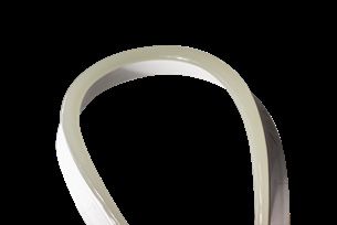
g. Bendable Channel                                                      10. MOUNT NEON IN CHANNEL OR WITH CLIPS
    First you must prep the channel for bending, start by                   Install channel or clips directly to the surface with screws. You
    marking the center and then 1 foot on each side, if bending             will need to pre-drill the holes before installation or use self-
    symmetrically. Use your bending tool, not bending past the              tapping screws when installing onto metal.
    bend radius, which can cause buckling or denting. For best
                                                                            Then gently press neon into the channel/clip, where it will lock
    results, bend about 4 degrees at a time and roll 6-12” beyond
                                                                            into place with the clamps. If you need to remove the neon, use
    on each side of the center bend. The longer the roll, the less
                                                                            a pliers to gently pinch the clamps to pull the neon out.
    chance of any indentation on the channel.
                                                                            For Aqueous Neon: Install channel directly to the surface with
        Note: 3916 should not be bent more than 38 degrees
                                                                            screws (required). You will need to pre-drill the holes before
         and 1806 should not be bent more than 25 degrees
                                                                            installation or cement screws when installing into cement.
    Once the channel is bent to the desired shape, measure and              Can be installed up to 6 feet below water surface. Note: Power
    mark where to cut, using metal rated saw blade. Use metal               supply needs to be mounted a MINIMUM of 12.33 feet from
    file to smooth edges as needed. Then slide the lens into the            water source.
    channel to determine the length to cut. Use tape (as seen in
    step #6) to prevent the lens from cracking.

                                                                           AFTER INSTALL IS COMPLETE
 h. Channeless Lens
    With Adhesive Backing: Once the LEDs are installed, install
                                                                          11. TURN POWER ON AT CIRCUIT BREAKER
    the lens by removing the adhesive backing and pressing it into
                                                                             Once your strip light or neon is connected, turn the
    place, starting from one end and working your way to the other.
                                                                             power on at the circuit breaker.
    With Screws (optional): Use the screws provided to secure the
    channeless lens into place.                                           12. CONTROL YOUR STRIP LIGHT OR NEON
                                                                             If using a controller, refer to the corresponding
8. INSTALL LENS                                                              control instructions for installation and set up.
 Once the strip light is in place, install the lens by pressing it into
 place, starting from one end and working your way to the other,
 then snap the solid end cap onto the open end.

                                                                               Do not attempt to make sharp bends. Excessive or
  IF INSTALLING NEON                                                           exaggerated bending and twisting can damage the circuit.

                                                                               NOTE: IP65 is water resistant & IP68 is protected against
 9. CUT THE CHANNEL FOR NEON                                                   water; power supply is NOT. Cutting Strip Light or Neon in
   Measure the length of the neon and subtract 3.62” to allow                  the field may void the UL Certification and Warranty.
   room for the end caps (subtract 3.15” for aqueous neon). Then
   measure the length of the channel and mark on the channel
   where you plan to cut.

   Cut using a metal rated saw blade. If cut is rough, use a metal
   file to smooth the edges. Clean any remaining slivers of metal to
   insure a clean install.

         Thank you, we appreciate your business!

                                                                                                                               novaflexled.com | 3
TROUBLESHOOTING: THE LIGHTS...
AREN’T ILLUMINATING THE RIGHT COLOR
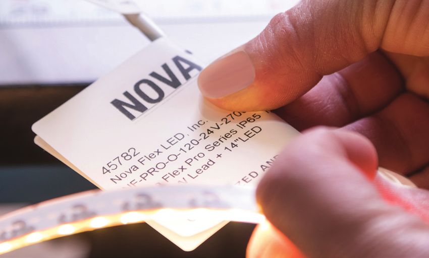
To properly address this problem, we’ll need to see what you are seeing. Take some
pictures of the wiring installation where input and output connections meet and be
prepared to e-mail them to us at customerservice@novaflexled.com. Please
also have your SO number available, which can be located on the white label of the
LED strip light.
Please note if you are seeing color variations, this could be due to color reflection
from surrounding surfaces.
ARE DIM
It is important to make sure that the project is not too far away from the power supply. Please reference our Voltage Drop Chart to assist in
determining the proper gauge wire for your project if needing to run over 15 ft. The voltage that the LEDs need is low and can diminish over
distance due to voltage drop. Refer to the Bill of Material to make sure you are using the proper light/power combination.
• If you are a licensed electrician and have a voltmeter, inspect the current going through the power supply using appropriate safety measures.
• If you are using a dimmer, make sure the dial on the dimmer is set to the brightest setting.
ARE NOT TURNING ON
The first thing we recommend in this situation is to verify that the lights are hooked up correctly and the polarity is correct. We always indicate
our wires by industry standard red=positive and black=negative. If you have hooked up the lights backwards, don’t worry - there are built-in
safety measures in the lights. If current attempts to run backwards, the LEDs will not turn on.
• If you are a licensed electrician and have a voltmeter, inspect the current going through the power supply using appropriate safety measures.
• If you are using one of our ‘quick connect’ power supplies, be sure that the barrels are making a proper connection.
• If you are using the RGB strip light series, make sure that the connection has enough wire exposed on the leads going into the controller
and they are all the way to the back of the terminals. If there is not enough wire, there won’t be a good connection to turn on the lights.
ARE FLICKERING, PULSING AND/OR ODDLY PUTTING OUT LIGHT
If you are using a dimming power supply, make sure your system is wired to a compatible dimmer switch. Refer to our Spec Sheets for a list of
compatible dimming switches. Confirm polarity of wiring, ensuring +/- are connected properly.
• If you are a licensed electrician and have a voltmeter, inspect the current going through the power supply using appropriate safety measures.
• Unplug the project and make sure that the solder connection is secure. Gently wiggle the solder points to make sure that the wires are not
falling off of the project. Then plug the project back in and try again.
• If the distance between the power supply and lights is greater than 15 ft, there can be loss of wattage. This can cause flickering.
ARE NOT STICKING SECURELY
Wipe down the surface using the supplied alcohol wipe to ensure you have a clean surface. If you are still not seeing a desired outcome, we
recommend applying some 3M Primer 94 to the surface or purchasing our Hard or Soft LED strip light clips. Our durable plastic clips are
designed to make sure that the lighting is securely where you want it to be. The clips need to be nailed or screwed into the surface.
If your project has long straight edges with a surface that doesn’t take to tape or if you want your project to have a diffused single light effect,
we offer aluminum channel. We will supply you with screws and clips to apply to the surface. If none of these options are possible, there’s
always double-sided tape or silicone to consider.
ARE TOO HOT
If you’re a licensed electrician and have a voltmeter, inspect the current going through your power supply using appropriate safety measures.
There should be no more than 12 or 24V DC entering the ribbon. While the LED’s produce very little heat, it is important to make sure that the
ribbon is spaced for proper air movement. LED’s have a max operating temp of 140° for IP65 and 175° for IP68.
ARE VERY HOT/MELTING
Turn off the lights and call us immediately at 1-800-595-6302. The lights are never supposed to do this.
If for any reason you are still having issues, please contact your distributer for support.
4 | novaflexled.comNOVA FLEX LED, INC. WARNINGS AND WAIVER
• Any installation of this product should be completed by a professional licensed electrician pursuant to all applicable governing laws, ordinances, regulations,
national and local electrical and building codes.
• This is an electronic product which is susceptible to damage if handled incorrectly. Improper soldering or modification may result in a voided warranty. Warranty
cases will be made at Nova Flex’s discretion based on multiple factors.
• Do not allow product to be punctured or penetrated by foreign objects; this can result in a short circuit.
• Do not connect product directly to a 120V AC power source. For best performance, do not load the DC power source more than 80% of its labeled rating.
• Any use of this product is entirely at your own risk. Failure to utilize and install this product in its proper manner could result in severe injury and/or property
damage.
• Keep out of reach of children.
This product is provided by the manufacturer “as is” “with all faults” without any warranties or representations, express or implied, including, but not limited to the
warranties of merchantability or fitness for a particular purpose. In no event shall manufacturer be liable for any special, incidental, punitive indirect or consequential
damages of any kind. Manufacturer offers this product and the user accepts it subject to the foregoing conditions, which may only be modified in a writing signed
by the manufacturer. See complete Terms & Conditions at novaflexled.com
VOLTAGE DROP CHART & WIRING DIAGRAMS
NOTE: Using the incorrect gauge wire can lead to issues such as flickering, light loss and altered color temp. The chart below shows an
approximation of gauge wire needed for a 100W system. *20 gauge NOT used for neon. View Spec Sheets for power supply compatibility.
STATIC 24V RIBBON & NEON RGB 24V RIBBON & NEON
MATERIAL CONDUCTOR # AMPS VOLTAGE PHASE MATERIAL CONDUCTOR # AMPS VOLTAGE PHASE
Copper 2 4 24 DC Copper 4 4 24 DC
WIRE GAUGE MAX DISTANCE (FT) VOLTAGE LOSS WIRE GAUGE MAX DISTANCE (FT) VOLTAGE LOSS
20* 29 4.91% 20* 59 4.99%
18 47 5.00% 18 86 4.52%
17 59 4.98% 17 115 4.85%
16 75 5.02% 16 150 5.02%
15 94 4.99% 15 185 4.91%
14 119 5.01% 14 230 4.84%
13 150 5.01% 13 285 4.76%
12 189 5.00% 12 360 4.76%
11 238 5.00% 11 445 4.67%
10 300 4.98% 10 550 4.58%
HARDWIRE, NON-DIMMING Strip Light: 20 Gauge Wire | Neon: 18 Gauge Wire
Electronic Non-Dimming Driver
AC POWER
Blue
N CN (Blue) V+ (Red)
OUTPUT
Static Strip Light or Neon
INPUT
L ACL (Brown) V- (Black)
Brown
*Ground
Ground *Only NF-PS-HLG100W2V-HW will have a ground wire.
120 VAC Switch (Non-Dimming)
288W Multi-Channel Non-Dimming Driver
Static Strip Light or Neon
LED Driver
White Static Strip Light or Neon
N
L - + - + - +
Black
Static Strip Light or Neon
Ground
novaflexled.com | 50-10V DIMMABLE with 0-10V dimmers; Strip Light: 20 Gauge Wire | Neon: 18 Gauge Wire
30W or 96W 0-10V Dimmable Driver
White (N) Red (+)
Black (-)
Black (L)
AC POWER LED Driver Gray
Violet
Ground
Static Strip Light or Neon
0-10V
Dimmer
288W 0-10V Multi-Channel Dimmable Driver
Static Strip Light or Neon
LED Driver
White Static Strip Light or Neon
N
L - + - + - +
Black
Gray Violet Static Strip Light or Neon
Ground
DIMMING Strip Light: 20 Gauge Wire | Neon: 18 Gauge Wire
E-Series MLV Dimmable Driver
AC POWER
INPUT OUTPUT
INPUT OUTPUT
Ground V+ (Red to Red)
L (Black)
L
N Static Strip Light or Neon
EZJ MLV Dimmable Driver
AC POWER
N (White) INPUT
OUTPUT
+
Static Strip Light or Neon
N -
Ground Ground
~
+
Ground OUTPUT Static Strip Light or Neon
L (Black) -
L
N OUTPUT
+
Static Strip Light or Neon
96W ELV Dimmable Driver
- +
Gray= White Wire
Dimmer
Static Strip Light or Neon
L N
120V
6 | novaflexled.comPLUG & PLAY Strip Light: 20 Gauge Wire | Neon: 18 Gauge Wire
AC POWER
Static Strip Light or Neon
NF-C-MF
Static Strip Light or Neon
NF-C-Y
Static Strip Light or Neon
LUTRON Strip Light: 20 Gauge Wire | Neon: 18 Gauge Wire
Wiring Diagram for 3-Wire Control
Switched Line/Hot (Black)
Static Strip Light or Neon
To 3-Wire - +
Dimmed Line/Hot (Orange)
Dimming Hi-Lume 1%
Control Neutral (White)
Ground
Wiring Diagram for EcoSystem Digital Control
Line/Hot (Black)
Static Strip Light or Neon
- +
To Line Neutral (White)
Hi-Lume 1%
Voltage Ground (Green)
E1 (Purple)
To EcoSystem
E2 (Purple)
Digital Link Ground
Wiring Diagram for LSD Model
Line/Hot Switched Line/Hot (L)
Static Strip Light or Neon
- +
3-Wire Dimmer/
To Line Voltage Module/Panel Dimmed Hot (DH)
Hi-Lume Premier
0.1% Constant
Voltage LED Driver
Neutral Ground Neutral (N)
Ground
novaflexled.com | 7S3i WIRELESS RECEIVER Strip Light: 20 Gauge Wire | Neon: 18 Gauge Wire
Static Strip Light or Neon Run #1
W- B- G- R- V+
-+-+
INPUT
Static Strip Light or Neon
OUTPUT
NF-S3i-WR-1009
NF-PS-HLG100W-24V-HW
120V AC (Line) Run #2
W- B- G- R- V+ v+ v-
Static Strip Light or Neon
120V AC (Line)
B- G- R- + V- v+ v-
OUTPUT
INPUT
NF-A-UNV
NF-PS-HLG100W-24V-HW
Adjustable Strip Light
Run #1
W- B- G- R- V+
-+-+
INPUT
Adjustable Strip Light
OUTPUT
NF-S3i-WR-1009
NF-PS-HLG100W-24V-HW
120V AC (Line)
W- B- G- R- V+ v+ v-
120V AC (Line) Run #2
W- B- G- R- + v+ v-
OUTPUT
INPUT
NF-A-UNV Adjustable Strip Light
NF-PS-HLG100W-24V-HW
Note: Gray Wire = White Wire
RGB Strip Light or Neon
Run #1
W- B- G- R- V+
-+-+
INPUT
OUTPUT
NF-S3i-WR-1009 RGB Strip Light or Neon
NF-PS-HLG100W-24V-HW
120V AC (Line)
W- B- G- R- V+ v+ v-
W- B- G- R- + v+ v-
120V AC (Line) Run #2
OUTPUT
INPUT
NF-A-UNV
RGB Strip Light or Neon
NF-PS-HLG100W-24V-HW
Note: Black Wire = Yellow Wire for Neon
RGBW Strip Light
Run #1
W- B- G- R- V+
-+-+
INPUT
OUTPUT
NF-S3i-WR-1009 RGBW Strip Light
NF-PS-HLG100W-24V-HW
120V AC (Line)
W- B- G- R- V+ v+ v-
W- B- G- R- + v+ v-
120V AC (Line) Run #2
OUTPUT
INPUT
NF-A-UNV
RGBW Strip Light
NF-PS-HLG100W-24V-HW
Note: Gray Wire = White Wire
8 | novaflexled.comYou can also read