Introduction to BER testing of WDM systems
←
→
Page content transcription
If your browser does not render page correctly, please read the page content below
This literature was published years prior to the establishment of Agilent Technologies as a company independent from Hewlett-Packard
and describes products or services now available through Agilent. It may also refer to products/services no longer supported by Agilent.
We regret any inconvenience caused by obsolete information. For the latest information on Agilent’s test and measurement products go to:
www.agilent.com/find/products
Or in the US, call Agilent Technologies at 1-800-452-4844 (8am–8pm EST)

          Introduction to
          BER testing of WDM systems

                                                                                          Application note 1299

                                                                                          Wavelength division multiplexing
                                                                                          (WDM) is a new and exciting
                                                                                          technology for migrating the core
                                                                                          optical transmission network to
                                                                                          higher bandwidths. The ability to
                                                                                          transfer multiple optical carriers
                                                                                          over the same span of fiber
                                                                                          promises almost unlimited
                                                                                          bandwidth.

                                                                                          However, the ultimate test for any
                                                                                          transmission medium is its bit
                                                                                          error ratio (BER) performance.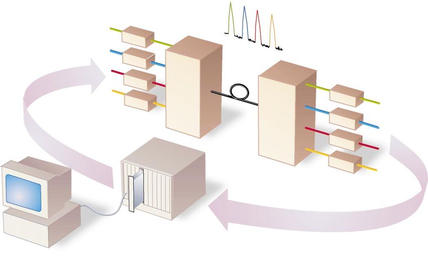
How WDM overlays
onto the network
If a network hotspot produces capacity shortfall problems, network
operators can now opt to deploy a WDM system to quickly expand
capacity on existing fiber links. For example, WDM equipment has
already been deployed to multiply the capacity of existing STM-16/
OC-48 links—by combining and carrying up to 16 STM-16/OC-48 signals
along the existing fiber path†. At the same time, upgrading of the
existing STM-16/OC-48 line terminal mux to WDM operation is also
readily achieved, providing increased bandwidth while retaining
existing tributary access and connections. The operation of a WDM
system can best be explained by looking at the sub-system level.
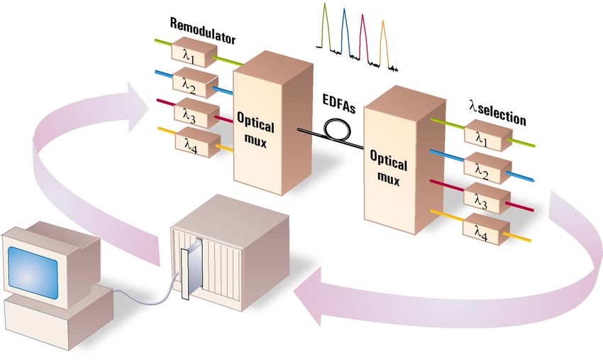
Figure 1.
Simplified
WDM system
configuration.
Figure 2.
Example output
spectrum for four
2.4 Gb/s laser
sources.
† Schemes are proposed carrying up to Laser sources and remodulators Optical multiplexer
32 STM-16/OC-48 signals. The transmitter of a WDM system produces The multiplexer (mux) couples together
‡ Currently, ITU-T draft recommen- laser signals at specific wavelengths and different wavelengths then combines them
dations O.mcs specify 43 WDM with a nominal spectral line spacing for transmission into a single mode fiber—
wavelengths. between them (Figure 2). Frequency maintaining the wavelength integrity of
separation is carried out using laser each optical carrier.
sources of specific frequencies, or using
parallel 1550 nm laser sources with a Fiber path and EDFAs
remodulator to obtain the required If an optical link is short, the transmission
frequencies. Laser sources are usually path will consist of nothing more than
distributed feedback (DFB) lasers, optical fiber. If the path is longer, say 50 to
typically working in the range 1530 to 100 km, then erbium doped fiber amplifiers
1565 nm‡. They offer good stability and a (EDFAs) are used for pre- and post-
narrow spectral width which is a pre- amplification. Where longer links are
requisite for dense-WDM (DWDM), where deployed, over 100 km, then EDFAs are
the spectral line spacing can be as narrow also used as intermediate amplifiers.
as 0.8 nm.
Optical demultiplexer and wavelength
If the WDM system is deployed within selection
existing STM-16/OC-48 fiber links then the The receive side employs a demultiplexer
remodulator also accepts the existing (demux) or decoupler to distribute the
1550 nm signal and remodulates it to the optical signal to the wavelength selectors.
chosen WDM wavelength, ready for the These devices define the optical bandwidth
wavelength multiplexing process. to recover the original tributary and
remove unwanted components.
2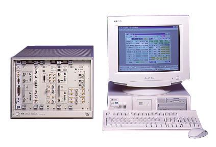
Impairments
affecting WDM
system performance
                                This application note focuses on the requirement for BER testing a
                                WDM system. There are several potential sources of impairments
                                associated with WDM components and optical fiber links. The main
                                impairments that affect BER performance are listed below.

                                Amplifier spontaneous emissions from             Dispersion
                                EDFAs                                            The characteristics of a fiber can cause
                                An accumulation of naturally occurring           wavelengths to propagate at different
                                emissions that may cause a reduction in          velocities through the fiber. This leads to
                                overall signal-to-noise ratio.                   pulse broadening and, ultimately, pulse
                                                                                 merging which results in errors on the
                                Gain flatness of EDFAs                           receiver detection circuit.
                                A measure of how flat the optical spectrum
                                remains after passing through the                Crosstalk between adjacent channels
                                amplifier. Ideally all wavelengths in the        This is the interaction between adjacent
                                WDM signal are amplified equally. Non-           channels in a WDM line signal. Because of
                                linearity needs to be compensated for,           the closeness of channel spacing, the
                                because ultimately it could lead to channel      contents of one channel can cause
                                failure.                                         interference in an adjacent channel,
                                                                                 introducing errors at the receiver after
                                Gain competition in EDFAs                        demultiplexing and channel selection.
                                This is associated with the allocation of
                                power to channels. Each EDFA has a               Four wave mixing
                                defined amount of optical power available        This occurs if components of existing
                                for amplifying incoming signals. Increasing      optical signals combine to produce a new
                                the bandwidth of the amplifier adds more         optical signal at a new wavelength.
                                channels but leads to an overall reduction
                                of power in existing channels.                   Simulated Brillouin scattering and
                                                                                 Raman scattering
                                Intrinsic and timing jitter                      A description of the interaction between
                                Jitter is the phase variation of a signal from   the optical signal and acoustic waves in the
                                its correct position in time. It can             fiber, and between the optical signal and
                                accumulate in a transmission network,            the fiber.
                                leading to errors. The remodulation stage
                                of a WDM system employs a clock
                                recovery and re-clocking stage which can
                                contribute to jitter on an incoming signal.

                                As any of these impairments could adversely affect the future fail-safe
                                operation of the network, they need to be evaluated properly and
                                corrected when implementing a WDM system design. For parametric
                                measurements such as power level and optical spectrum checks use a
                                wavelength meter and an optical spectrum analyzer.

For information on diagnosing
individual WDM impairments,
refer to the DWDM Components
Test Guide 5965-3124E.

                                3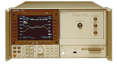
Evaluating BER
performance

                             Conclusive testing of BER performance (and other impairments) in a
                             WDM system requires the duplication, as close as possible, of an
                             in-service situation. Loading up the tributaries of a WDM system with
                             dynamic, uncorrelated test signals gives a good simulation of live traffic.
                             A typical test setup requires multiple 2.4 Gb/s optical sources of
                             network quality, using DFB lasers or equivalent. Testing also requires
                             wavelengths from the ITU-T WDM grid in order to mimic or test beyond
                             system designs. An OC-48/STM-16 BER analyzer with SONET/SDH
                             frame structures will simulate the traffic of a real network, and if it
                             offers a modular, scaleable transmit/receive measurement capability
                             would be ideal for WDM system testing.
        Figure 3.
        Ideally, BER
        performance
        checks on a WDM
        system would use
        uncorrelated,
        parallel PRBS test
        signals to verify
        transmission.

                             1. Tributary-side BER testing

                             Once assembled, WDM systems are usually 'soak tested'. That is, an end-
                             to-end BER test is performed across all tributaries of the WDM system.
                             Each tributary test is typically 3–4 hours duration due to the low
                             residual BER levels of WDM systems.

                             Soak testing can be approached in a number of ways.
                             1. Using a single transmit/receive optical source with optical switches
                                to test each tributary in turn.
                             2. Using an optical splitter on the transmit output of an optical source
                                to load up all inputs of the WDM mux, then using an optical switch
                                at the output for measuring BER on each receive tributary in turn.
                             3. Using mulitple transmit/receive optical sources to allow all inputs
                                of the mux to be loaded and to allow simultaneous BER
                                measurement on all receive tributaries.

                             Approach 1 may be sufficient for a functional test of a proven design,
                             but testing each tributary in turn is inefficient. This approach often
                             results in a trade-off on the amount of time spent measuring each
                             tributary—in order to reduce overall test time. Simply expressed, we
                             can say that . . .

                             Overall test time = number of WDM channels × BER test time per channel

                             A further limitation is that loading each tributary in turn may not
                             produce or detect the impairments described in the previous section.
                             Any BER estimate from this approach may therefore be unreliable. If
                             there is any instability in the system design then this approach is not
                             recommended.

                             4
Approach 2 may also result in a trade-off in test time, but removes the
                                          need for optical switching on the transmit side and allows all tributaries
                                          to be loaded. Most of the WDM impairments will emerge in this
                                          configuration. However, as the tributary test signals are identical, this
                                          approach is less likely to highlight crosstalk problems. In general, this
                                          BER estimate will be a good approximation.

                                          Approach 3 offers the best solution, in terms of both test time and
                                          thoroughness of test. Having independent optical sources means that
                                          the test signals are uncorrelated across the WDM tributary inputs. The
                                          multiple receive capability allows tributary BER measurements to be
                                          made in parallel, reducing overall test time significantly and providing a
                                          more accurate means of identifying problem tributaries by cross
                                          correlation of BER performance.

                    Figure 4.
                    A modular,
                    scaleable
                    transmit/receive
                    measurement
                    capability is ideal
                    for WDM system
                    testing.

Multiport configuration and
parallel measurements allow
easy cross-correlation of test
results.

                                          5
2. In-service BER testing
Accessing tributaries for test when the WDM system is carrying live
traffic is impractical. Some network monitoring capability may be built
into the WDM but it is yet unclear how comprehensive and informative
this capability will become. In any case, because of system aging, in-
service testing a WDM system requires measurements of both BER
performance and optical parameters.
The present strategy for maintaining the performance of a WDM system
relies on examination of the optical spectrum of the WDM signal to
ensure optical wavelength and power levels are within established
limits. These tests are completed using a waveform multimeter and
perhaps an optical spectrum analyzer (OSA) for higher resolution
measurements. These measurements are a good indication of system
performance but not an absolute, quantifiable measure. This can only be
achieved with a BER measurement and the challenge is how to access a
channel within a WDM line signal to make BER testing possible.
Using an OSA with a monochromator allows individual tributaries to be
isolated and dropped to a BER analyzer. The analyzer can then perform
in-service B1 parity error measurements on the live signal. So BER
performance can be checked for any change in channel performance
detected by parametric testing.
Figure 5. Optical Optical
The mono- Remodulators mux demux λ selection
chromator of an λ1
optical spectrum λ1
EDFAs
analyzer can act 2.4 Gb/s λ2 2.4 Gb/s
as a tunable optical fiber optic λ2 fiber optic
preselector to drop transmission λ3 transmission
a suspect channel signals λ3 signals
to a BER analyzer. λ4
λ4
λ2
O/H Optics
Optical
rx spectrum
tx tx tx tx
analyzer
Scaleable
BER analyzer
Periodically checking in-service BER performance could be used as a
vital pro-active measure, highlighting any degradation in quality of
service (QoS) before it impacts the service user. Further, for long term
monitoring, a maintenance strategy could specify that a WDM channel
be allocated as a test channel. This test channel could be 'hard-wired' by
the OSA to the BER analyzer, then be monitored continuously as a
measure of overall system performance. This would achieve a time-
stamped record of QoS with no impact on throughput of traffic. The test
For more information on channel could be allocated from any one of the channels carried in the
creating a tunable SONET/SDH WDM system and could be switched periodically across the output
BERT for WDM line testing, refer stream to check for non-linearities in system performance.
to product note 5965-2741E.
63. BER testing and jitter
In SONET/SDH networks, jitter is a serious threat to quality of service.
Controlling intrinsic jitter levels is a priority, and conformance testing of
a SONET/SDH network usually includes some BER testing combined
with jitter analysis. Later, when a network is operational, the level of
jitter is monitored to ensure it remains inside ITU-T recommended
levels. Because WDM is being overlaid onto the SONET/SDH
infrastructure, it too must meet the current jitter requirements. The two
key jitter measurements are jitter transfer and jitter tolerance.
Jitter transfer Jitter tolerance
This is a measure of jitter gain across any This a measure of BER performance versus
element or section of the network. applied jitter. A jitter tolerance
measurement is used to verify an interface
Jitter transfer (dB) = 20 log (Jitter out / Jitter in) can withstand defined jitter levels and
perform error free. Typically the test signal
It is important to measure jitter transfer is applied to the input stage of the WDM
across a WDM system to ensure that there remodulators with defined levels of jitter at
is no jitter contribution from the clock different frequencies, and the BER
recovery stages present in the performance is measured on the output
remodulators. Using a jitter analyzer with tributary of the demultiplexer. The jitter
low intrinsic jitter performance is the tolerance measurement masks have been
most accurate method to measure the defined by the ITU-T, and having a test set
jitter contribution in a WDM system. with these masks built-in makes
Typically a test signal (as jitter free as measurements faster and simpler.
possible) is applied to the input stage of
the WDM remodulators and the jitter is
measured on the output tributary of the
demultiplexer.
Having a jitter
analyzer that
displays the results
in decibels (dB) will
allow a quick
comparison with the
ITU-T jitter
standards.
For more information on
jitter measurement techniques,
refer to Application Note 1267
"Frequency-agile jitter
measurement system"
(5963-5353E).
7For more information about Hewlett-
Packard test & measurement products,
applications, services, and for a current
sales office listing, visit our web site,
http://www.hp.com/go/tmdir. You can also
HP 75000 Series 90 contact one of the following centers and
modular telecom analyzer ask for a test and measurement sales
A scaleable electrical/optical transmit and representative.
receive tester for SONET, SDH and WDM
systems. Use for loading system inputs, United States:
and for BER and jitter measurements to Hewlett-Packard Company
SONET/SDH standards. Test and Measurement Call Center
P.O. Box 4026
Englewood, CO 80155-4026
1 800 452 4844
Canada:
Hewlett-Packard Canada Ltd.
HP 37778A 5150 Spectrum Way
STM-16/OC-48 test set Mississauga, Ontario
Comprehensive testing at 2.488 Gb/s, L4W 5G1
including BER and jitter analysis to (905) 206 4725
SONET/SDH standards.
Europe:
Hewlett-Packard
European Marketing Centre
P. O. Box 999
1180 AZ Amstelveen
The Netherlands
(31 20) 547 9900
HP 71451B
Japan:
optical spectrum analyzer
Hewlett-Packard Japan Ltd.
In addition to optical sources, this analyzer
Measurement Assistance Center
can characterize optical-to-optical devices
9-1, Takakura-Cho, Hachioji-Shi
such as couplers, filters, isolators, switches
Tokyo 192, Japan
and WDM muxes.
Tel: (81) 426 56-7832
Fax: (81) 426 56-7840
Latin America:
Hewlett-Packard
Latin American Region Headquarters
5200 Blue Lagoon Drive
HP 86120B 9th Floor
multi-wavelength meter Miami, Florida 33126
For 700 nm to 1650 nm. Offers fast USA
measurement of wavelength, amplitude, (305) 267 4245/4220
drift and signal-to-noise ratios of up to 100 Fax: (305) 267-4288
discrete laser lines.
Australia/New Zealand:
Hewlett-Packard Australia Ltd.
31-41 Joseph Street
Blackburn, Victoria 3130
Australia
Tel: 1 800 629 485 (Australia)
Tel: (0800) 738 378 (New Zealand)
Fax: (61 3) 9210 5489
Asia Pacific:
Hewlett-Packard Asia Pacific Ltd.
17-21/F Shell Tower, Times Square
1 Matheson Street, Causeway Bay
Hong Kong
Tel: (852) 2599 7777
Fax: (852) 2506 9285
© Hewlett-Packard Limited 1997
Printed in USA
Data subject to change
5966-0911E 12/97You can also read