Multivendor 100G Coherent DWDM Line-Side Interoperability
←
→
Page content transcription
If your browser does not render page correctly, please read the page content below
White Paper

Multivendor 100G Coherent DWDM
Line-Side Interoperability
Juniper-Telefonica Joint Field Trial

                                                 1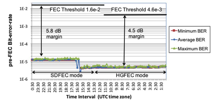
Multivendor 100G Coherent DWDM Line-Side Interoperability                                                                                                                                                                           White Paper

                Table of Contents
                Executive Summary ........................................................................................................................................................................................................ 3
                Introduction......................................................................................................................................................................................................................... 3
                100G Line-Side Interoperability.................................................................................................................................................................................. 3
                100G Coherent Pluggable Interfaces........................................................................................................................................................................ 4
                Field Trial Topology ......................................................................................................................................................................................................... 4
                      Test Case 1: Boca Raton and Jacksonville........................................................................................................................................................ 5
                      Test Case 2: Boca Raton and Jacksonville Loopback...................................................................................................................................7
                      Test Case 3: Juniper-Cisco Line-Side Interoperability................................................................................................................................. 8
                Conclusion......................................................................................................................................................................................................................... 10
                About Juniper Networks............................................................................................................................................................................................... 10

©2017, Juniper Networks, Inc.                                                                                                                                                                                                                        2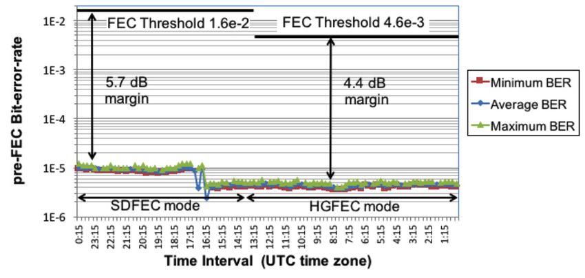
Multivendor 100G Coherent DWDM Line-Side Interoperability                                                                        White Paper

                Executive Summary
                The ever-increasing demand for network capacity is driving the deployment of both multi-terabit core routers as well
                as terabits of dense wavelength-division multiplexing (DWDM) transport capacity in today’s networks. At the transport
                layer, the use of coherent detection and digital signal processing (DSP) in 100G DWDM transceivers has revolutionized
                optical transport by vastly simplifying the design, deployment, and performance monitoring of transport networks,
                quickly establishing 100G coherent DWDM transceivers as the technology of choice for metro, regional, long-haul,
                and submarine transport networks. As a result, 100G coherent DWDM transceivers have evolved from their initial
                deployments1 in 2009 and 2010 into a mature technology with more than 200,000 ports deployed2 worldwide in 2015.

                This white paper describes the results of a field trial in the Telefonica International network between Boca Raton and
                Jacksonville, Florida. The DWDM interfaces are integrated on Juniper Networks and Cisco routers, with the goal of
                demonstrating how 100G coherent DWDM line-side interoperability and standardized pluggable DWDM coherent optics
                improve the flexibility of next-generation packet-optical transport networks.

                Introduction
                Today’s networks rely on large numbers of standards and implementation agreements to ensure multivendor
                interoperability at the optical transport network (OTN), Ethernet, and IP/MPLS network layers. However, at the optical
                transport layer, which is where 100G coherent DWDM transceivers reside, proprietary implementations have dominated.
                The first generation of 100G coherent DWDM transceivers required extensive research and development in both optical
                and digital signal processing technologies. Therefore, the use of discrete performance-optimized optical components,
                best-in-class proprietary DSP algorithms, and proprietary forward error correction (FEC) codes were initially critically
                important to gain a competitive advantage in 100G deployments. Now that 100G dual polarization-quadrature phase
                shift keying (DP-QPSK) is a mature technology, it is highly preferable that DWDM transceivers from different system
                vendors be interoperable at the optical transport layer to simplify the deployment of multivendor networks. Line-side
                interoperability requires the use of a standardized FEC code as well as standardized OTN framing and common DP-
                QPSK symbol mapping.

                100G Line-Side Interoperability
                For a variety of reasons, most transport networks have DWDM transceivers from different vendors—legacy installations,
                technology redundancy, different optical performance requirements (metro versus long haul), or simply for commercial
                reasons. Without line-side interoperability, each 100G coherent DWDM transceiver needs to be bookended by an identical
                DWDM transceiver, significantly reducing flexibility in network deployments. Therefore, line-side interoperability between
                100G coherent DWDM transceivers from different vendors is tremendously beneficial for network simplicity and optimization.

                Line-side interoperability is particularly relevant when the 100G coherent DWDM transceivers are integrated into the routing
                platforms. IP-optical integration simplifies network deployments by reducing budget, space, and power consumption
                while enabling faster service turn-up and more capabilities for multilayer optimization. The tighter integration between
                the network’s IP/MPLS and DWDM transport layers is therefore becoming ever more important in next-generation network
                architectures. Since multivendor interoperability is common for both IP/MPLS network protocols as well as Ethernet client
                interfaces, the same expectation is set for DWDM interfaces integrated on router line cards.

                The 100G coherent DWDM line cards for Juniper Networks® MX Series 3D Universal Edge Routers support a variety of
                FEC modes, ensuring maximum flexibility in different network deployments. For multivendor deployments, interoperable
                FEC modes are supported based on generic FEC (GFEC) and the high-gain FEC (HG-FEC) codes. In addition, a
                proprietary FEC mode with soft-decision decoding is supported, enabling maximum optical performance and (ultra)
                long-haul transmission.

                GFEC is a Reed-Solomon FEC code standardized by the ITU-T in G.975. Included in the ITU-T G.709 standardized OTU4
                framing standard, GFEC is widely supported across transport platforms3. Compared with today’s state-of-the-art FEC
                performance, GFEC’s 6.2 dB coding gain is fairly moderate, limiting its applicability to metro networks at 100G bit rates.
                However, since it is widely supported across many transport platforms, it has the unique ability to enable line-side
                interoperability across most platforms in the industry.

                HG-FEC is specifically designed to preserve the standardized OTU4 frame for 100GbE client signals with a bit rate of
                111.81 Gbps, but it provides a higher coding gain through an advanced code structure and iterative decoding. The HG-
                FEC code is based on a Bose-Chaudhuri-Hocquenghem (BCH) code with a rate R = 239/255 (6.7% overhead). The
                iterative hard-decision decoding algorithm results in a pre-FEC BER threshold of 4.6e-3 for a post-FEC BER of 1e-15,
                which translates into a 9.4 dB NCG4. The HG-FEC code, therefore, provides a significantly higher NCG compared to GFEC,
                enabling 100G line-side interoperability over regional and long-haul transmission distances of more than 1000 km.

                1
                    G. Wellbrock and T.J. Xia, “The road to 100G deployment” IEEE Communications Magazine, p. S14-S18 (2010)
                2
                    Networking Ports: 1G, 2.5G, 10G, 40G, 100G Market Tracker, 2nd-Edition 2015, Infonetics Research (2015)
                3
                    ITU-T Rec. G.709, “Interfaces for the optical transport network” (2012)

©2017, Juniper Networks, Inc.                                                                                                                3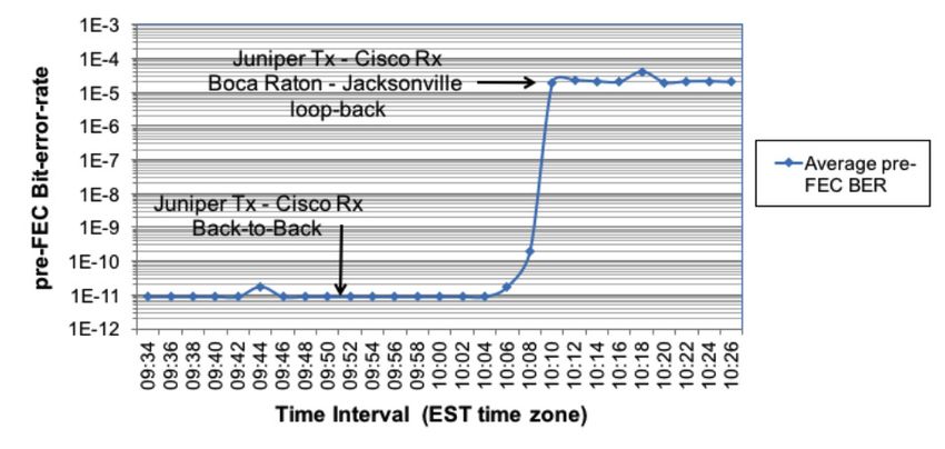
Multivendor 100G Coherent DWDM Line-Side Interoperability                                                                              White Paper

                Since HG-FEC mode uses a hard-decision decoder, it is only moderately complex to implement and can be integrated
                into the DSP ASIC, a separate OTN famer ASIC, or implemented in an FPGA. This implementation flexibility makes the
                HG-FEC code ideally suited for line-side interoperability across different 100G transport platforms. As a result, HG-FEC
                has become a de facto industry standard that is implemented in 100G DWDM transceivers and IPoDWDM line cards
                from multiple system vendors.

                The soft-decision FEC (SD-FEC) code supported on the 100G DWDM interface for MX Series routers is based on a Turbo
                Product Code (TPC) with 15% overhead and a theoretical 10.8 dB coding gain. A soft-decision decoder architecture
                optimizes the code to maximize optical performance, making it particularly well suited for long-haul deployments
                supporting transmission distances of 2000 km or more in transport networks.

                100G Coherent Pluggable Interfaces
                The 100G DWDM line cards used in this field trial are equipped with CFP2-ACO-pluggable DWDM coherent optics. The
                analog coherent optics (ACO) architecture, which decouples the optical and electronic functionality of a 100G coherent
                DWDM interface, is very promising. The CFP2-ACO pluggable form factor integrates all optical functionality required
                for a 100G coherent transceiver into the CFP2 pluggable form factor, whereas the DSP ASIC that implements signal
                equalization, forward error correction, and framing is still placed on the line card. ACO therefore refers to the high-speed
                analog interface between the CFP2-ACO pluggable form factor and the DSP ASIC on the line card.

                Decoupling the optical and electronic functions of the 100G coherent DWDM interface allows CFP2-ACO manufacturers
                to focus on state-of-the-art optical integration and miniaturization, which is required to build a full 100G coherent
                optical front end within the space and power constraints of a CFP2 form factor. System vendors building 100G coherent
                DWDM line cards can instead focus on the required high-speed electronics design, vastly simplifying the design,
                manufacturing, and testing of the line card. This disaggregated architecture also improves interoperability since the
                same pluggable coherent optics implementation can be used across different transport platforms.

                The ACO architecture has been defined in an implementation agreement by the Optical Internetworking Forum (OIF) ,
                ensuring broad industry support. CFP2-ACO pluggable interfaces, available from many of the major optical transceiver
                vendors worldwide, can be built using different optical integration technologies, including Indium Phosphate (InP)
                or Silicon Photonics (SiP), ensuring a healthy ecosystem with significant investment in optical integration to further
                develop and enhance the pluggable optics architecture. Although originally conceived for 100G metro solutions, the ACO
                architecture is proven to enable excellent optical performance for 100G data rates, making it suitable for deployment in
                metro, regional, and even long-haul transport networks.

                                                                             Figure 1: CFP2-ACO pluggable DWDM optics

                Field Trial Topology
                The 100G coherent DWDM field trial used two Juniper Networks MX2020 3D Universal Edge Router devices deployed in
                Boca Raton and Jacksonville, Florida. The 20-slot MX2020, Juniper’s flagship router for provider edge networks, is widely
                used in edge, peering, and core network deployments. The MX2020 chassis scales up to 32 terabit full-duplex traffic
                throughput, making it ideal for next-generation network architectures. A Cisco ASR 9904 router, also located in Boca
                Raton, is used during the field trial for the multivendor line-side interoperability test cases. ASR 9904 is part of the ASR
                9900 Series, representing Cisco’s paradigm in edge and core routing.

                The DWDM transport link used during the field trial is part of Telefonica’s network running between Boca Raton and
                Jacksonville, with a one-way distance of approximately 515 km. The link consists of six fiber spans, with five in-line
                EDFAs, one intermediate ROADM, and two ROADMs with DWDM multiplexers at the endpoints. The transmission link
                consists of 470 km of Large Effective Area Fiber (LEAF, G.655) as well as a single 45 km fiber span of standard single-
                mode fiber (SSMF, G.652). The link is dispersion uncompensated—hence the accumulated chromatic dispersion is
                compensated through digital signal processing in the receiver, delivering the best optical performance for 100G coherent

                4
                    B.P. Smith et al., “Staircase Codes: FEC for 100 Gb/s OTN,” J. Lightwave Technol., Vol. 30, no. 1, p. 110 (2012)
                5
                    OIF Implementation agreement for CFP2 Analogue Coherent Optics Module, OIF-CFP2-ACO-01.0 (2016)

©2017, Juniper Networks, Inc.                                                                                                                   4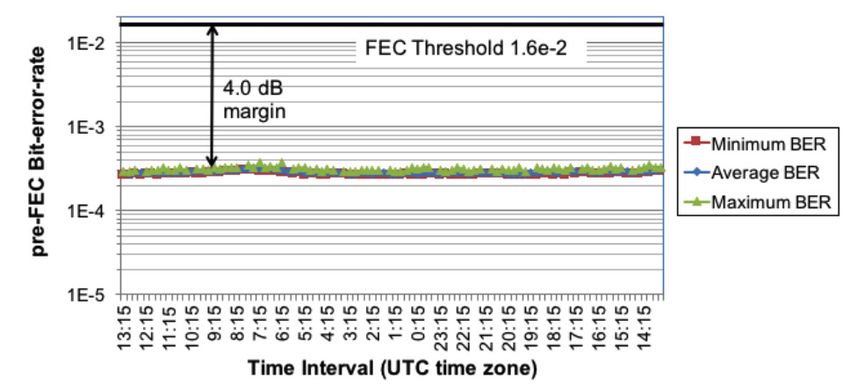
Multivendor 100G Coherent DWDM Line-Side Interoperability                                                                              White Paper

                DWDM transceivers. The 100G DWDM channel is transported as alien wavelength over a third-party DWDM platform,
                simultaneously carrying both production traffic and the channel-under-test during the field trial. The 100G DWDM
                channel-under-test is located at 1561.42 nm, where an appropriate guard-band ensured there was no interference
                between co-propagating DWDM channels.

                                                                                     Jacksonville
                                                                                                 Juniper
                                                                                                 MX2020

                                                                                 1030 km
                                                                                (2 x 515 km)

                                                                                      Boca Raton

                                                                                                  Juniper MX2020
                                                                                                and Cisco ASR 9004

                         Figure 2: The transport link used during the field trial—515 km one-way between Boca Raton and Jacksonville
                                                              and 1030 km in total for the loopback

                Test Case 1: Boca Raton and Jacksonville
                The first test scenario consists of 100G unidirectional transport between the two MX2020 routers, each using one 100G
                coherent DWDM line card. In this first test scenario, both the optical performance in the SD-FEC and HG-FEC modes are
                tested during an overnight soak test to ensure long-term stability. The measured pre-FEC BER values are shown in Figure 4.

                The minimum, maximum, and average pre-FEC BER is measured throughout the entire soak test. The minimum and
                maximum values represent the one-second lowest, respectively highest, pre-FEC BER interval during each 15-minute
                period. Comparing the average and maximum pre-FEC BER reveals any potential error bursts or transients. As Figure 4
                shows, the small difference between the two indicates that the transport link was stable throughout the 24-hour soak test.

                In HG-FEC mode, an average pre-FEC BER of 4.7e-6 (12.9 dBQ) is measured, whereas the average pre-FEC BER in SD-
                FEC mode is 1.3e-5 (12.5 dBQ). This 0.4 dB difference in measured Q-factor is the result of the higher bit rate in SD-FEC
                mode (120.58 Gbps) compared to HG-FEC mode (111.81 Gbps), which slightly increases the measured pre-FEC BER.
                Changing the bit rate from 111.81 Gbps to 120.58 Gbps would theoretically result in a 0.33 dB difference, which is close to
                the measured 0.4 dB performance difference.

                                            Boca Raton                                                    Jacksonville

                            et-19/0/0             1561.42 nm                                              1561.42 nm            et-19/0/0
                             10.19.0.1                                                                                           10.19.0.1
                                                                            515 km

                                                                DWDM                            DWDM
                                                               platform                        platform

                                         MX2020                                                                        MX2020

                        Figure 3: Unidirectional transmission test between Boca Raton and Jacksonville over a total distance of 515 km

©2017, Juniper Networks, Inc.                                                                                                                   5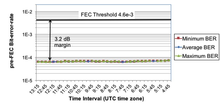
Multivendor 100G Coherent DWDM Line-Side Interoperability                                                                    White Paper

                   Figure 4: 24-hour soak test of the link between Boca Raton (Tx) and Jacksonville (Rx)—the 100G DWDM interfaces are
                                                    switched from HG-FEC to SD-FEC mode during the test

                The SD-FEC mode has a higher system margin despite the somewhat higher pre-FEC BER measured. Based on the
                difference between maximum pre-FEC BER and the FEC threshold, the system margin is 5.8 dB and 4.5 dB for SD-FEC
                and HG-FEC, respectively. The difference of 1.3 dB in system margin follows from the 0.4 dB difference in measured pre-
                FEC BER and the 1.7 dB difference in absolute coding gain between the two FEC modes. This aligns with the expected
                net coding gain difference of 1.4 dB.

                Figure 5 shows the measured optical performance during the same soak test, but now with the transmitter in
                Jacksonville and the receiver in Boca Raton. Transmission performance is very similar, with a worst-case 4.5 dB margin
                in HG-FEC mode and a 5.8 dB margin in SD-FEC mode. Both directions therefore show stable optical performance, with
                significant system margin over 515 km in both SD-FEC and HG-FEC modes.

                   Figure 5: 24-hour soak test of the link between Jacksonville (Tx) and Boca Raton (Rx)—the 100G DWDM interfaces are
                                                        switched from HG-FEC to SD-FEC during the test

©2017, Juniper Networks, Inc.                                                                                                           6
Multivendor 100G Coherent DWDM Line-Side Interoperability White Paper
Boca Raton Jacksonville
et-19/0/0 515 km 1561.42 nm et-19/0/0
10.19.0.1 10.19.0.1
515 km
Loopback
DWDM DWDM
platform platform
MX2020 MX2020
Figure 6: Boca Raton to Jacksonville with loopback in Jacksonville—both transmitter and receiver are in Boca Raton
and the total transmission distance is 1030 km
Test Case 2: Boca Raton and Jacksonville Loopback
In the second test case, the total transmission distance is doubled to 1030 km by switching to optical loopback on the
ROADM in Boca Raton and terminating the wavelength on the same MX2020 line card in Jacksonville.
Figure 7: 24-hour soak test of the link between Jacksonville and Boca Raton with loopback in Jacksonville—the interfaces
are configured to SD-FEC mode
The soak test over the loopback link confirms long-term performance is stable, with an average measured pre-FEC BER
of 2.8e-4 and a worst-case system measured pre-FEC BER of 3.7e 4 in SD-FEC mode (see Figure 7). The worst-case
system margin with respect to the SD-FEC threshold is therefore equal to 4.0 dB, showing stable long-term optical
performance with an excellent operating margin over 1030 km.
©2017, Juniper Networks, Inc. 7Multivendor 100G Coherent DWDM Line-Side Interoperability White Paper
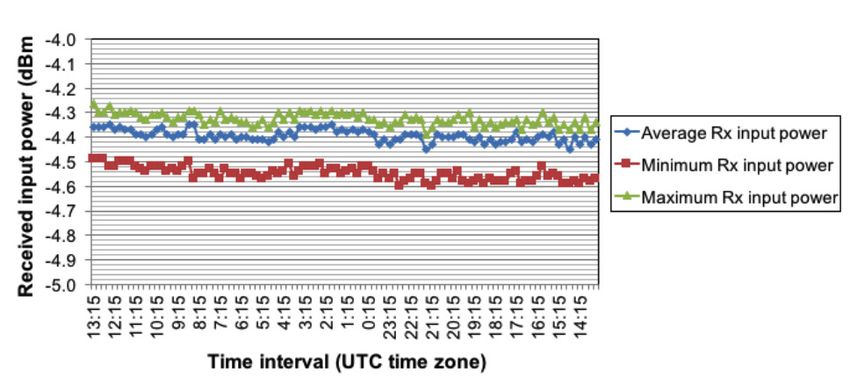
Figure 8: Received optical power during a 24-hour soak test on the looped-back Boca Raton to Jacksonville link
with both transmitter and receiver in Jacksonville
The optical power incident on the receiver is also a parameter that can be used to monitor the stability of the
transmission link. The 100G coherent DWDM line cards allow for a very granular measurement of the received optical
power, including minimum, average, and maximum power measurements. Figure 8 shows the measured received input
power for transmission over 1030 km on the transport link between Boca Raton and Jacksonville, with loopback in
Jacksonville. The measurements indicate less than 0.4 dB in power fluctuations in 1-second time interval granularity over
the entire 24-hour soak window when comparing the minimum and maximum received optical power. This indicates
extremely stable optical power control of the transmission link, which is well matched by the stable pre-FEC BER
performance measured during the test window.
Test Case 3: Juniper-Cisco Line-Side Interoperability
In the third test case, the test setup is switched from Juniper routers on both endpoints to a line-side interoperability
test scenario between a Juniper Networks MX2020 3D Universal Edge Router and Cisco ASR 9004 router. Both devices
are located in Boca Raton, and the same 1030 km transport link from Boca Raton to Jacksonville with loopback in
Jacksonville is used.
Boca Raton Patch panel Jacksonville
RX
TX
RX Cisco
et-19/0/0 ASR004
10.19.0.1
TX
MX2020 DWDM platform DWDM platform
Figure 9: Boca Raton to Jacksonville with loopback over 1030 km and connecting a Cisco 100G DWDM
transmitter (in the ASR 9004) with the Juniper 100G DWDM receiver (in the MX2020)
This test case aims to demonstrate multivendor line-side interoperability for 100G coherent DWDM interfaces and
show that this is feasible with an optical performance comparable to proprietary 100G DWDM interfaces. In the first
test, as shown in Figure 9, the transmitter of the ASR 9004 100G DWDM line card transmits the signal over the long-
haul transport link. The signal received from the transmission link is fed into the receiver on the MX2020 100G DWDM
line card, which is also used to collect the optical performance monitoring statistics. The transmitter of the MX2020
IPoDWDM line card is connected back to back to the receiver on the ASR 9004 IPoDWDM line card.
©2017, Juniper Networks, Inc. 8Multivendor 100G Coherent DWDM Line-Side Interoperability White Paper
Figure 10: Soak test of the link between Jacksonville and Boca Raton with loopback in Jacksonville over 1030 km
with Cisco 100G DWDM transmitter and Juniper 100G DWDM receiver
Optical performance monitoring statistics for the multivendor line-side interoperability scenario are collected during a
soak test running for more than eight hours, as shown in Figure 10. The worst-case system measured pre-FEC BER during
the measurement time frame was 7.6e-5, with an average pre-FEC BER of 6.7e-5. The measured pre-FEC BER translates
in a worst-case system margin relative to the HG-FEC threshold of 3.2 dB. This confirms excellent optical transmission
performance over 1030 km using the HG-FEC mode to enable line-side interoperability between the Juniper and Cisco
100G DWDM router line cards.
Boca Raton Patch panel Jacksonville
RX
TX
RX Cisco
et-19/0/0 ASR004
10.19.0.1
TX
MX2020 DWDM platform DWDM platform
Figure 11: Soak test of the link between Jacksonville and Boca Raton with loopback in Jacksonville over 1030 km
with Juniper 100G DWDM transmitter and Cisco 100G DWDM receiver
Finally, in a second test, the transmitter and receiver directions are switched, with the 100G coherent DWDM line card
in the Juniper MX2020 router transmitting the signal over the long-haul DWDM link and the 100G coherent DWDM
interface in the Cisco ASR 9004 receiving the signal. Optical performance monitoring statistics are collected on the
Cisco ASR 9004 DWDM line card over an 18-minute period, as shown in Figure 12. The worst-case average pre-FEC BER
(over two-minute time slots) is 4.1e-5, with an average pre-FEC BER measured over the 18-minute measurement period
of 2.3e-5.
©2017, Juniper Networks, Inc. 9Multivendor 100G Coherent DWDM Line-Side Interoperability White Paper
Figure 12: Soak test of the link between Jacksonville and Boca Raton with loopback in Jacksonville over 1030 km
with Juniper 100G DWDM transmitter and Cisco 100G DWDM receiver
Conclusion
The field trial over 515 km between Boca Raton and Jacksonville yields a system margin in excess of 5.7 dB in SD-FEC
mode and 4.4 dB in HG-FEC mode. Including loopback in Jacksonville and extending the total transmission distance
to 1030 km we measured a 4 dB margin in SD-FEC mode. All measurements show excellent long-term stability with
minimum performance variation during overnight soak tests.
The multivendor line-side interoperability measurements between 100G coherent DWDM router line cards on the Juniper
Networks MX2020 3D Universal Edge Router and Cisco ASR 9004 show excellent optical performance. A 3.2 dB margin
is measured on the Boca Raton to Jacksonville link with loopback in Jacksonville.
About Juniper Networks
Juniper Networks challenges the status quo with products, solutions and services that transform the economics of
networking. Our team co-innovates with customers and partners to deliver automated, scalable and secure networks with
agility, performance and value. Additional information can be found at Juniper Networks or connect with Juniper on Twitter
and Facebook.
Corporate and Sales Headquarters APAC and EMEA Headquarters
Juniper Networks, Inc. Juniper Networks International B.V.
1133 Innovation Way Boeing Avenue 240
Sunnyvale, CA 94089 USA 1119 PZ Schiphol-Rijk
Phone: 888.JUNIPER (888.586.4737) Amsterdam, The Netherlands
or +1.408.745.2000 Phone: +31.0.207.125.700
Fax: +1.408.745.2100 Fax: +31.0.207.125.701
www.juniper.net
Copyright 2017 Juniper Networks, Inc. All rights reserved. Juniper Networks, the Juniper Networks logo, and
Junos are registered trademarks of Juniper Networks, Inc. in the United States and other countries. All other
trademarks, service marks, registered marks, or registered service marks are the property of their respective
owners. Juniper Networks assumes no responsibility for any inaccuracies in this document. Juniper Networks
reserves the right to change, modify, transfer, or otherwise revise this publication without notice.
2000653-001-EN Jan 2017You can also read