Rapid Prototyping of a Frequency Hopping Ad Hoc Network System
←
→
Page content transcription
If your browser does not render page correctly, please read the page content below
Rapid Prototyping of a
        Frequency Hopping Ad Hoc Network System
                          Martin Braun, Nico Otterbach, Jens Elsner, and Friedrich K. Jondral
                    Communications Engineering Lab, Karlsruhe Institute of Technology (KIT), Germany
                                                D-76128 Karlsruhe, Germany
             martin.braun@kit.edu, nico.otterbach@student.kit.edu, jens.elsner@kit.edu, friedrich.jondral@kit.edu

   Abstract—Wireless networks in-the-loop is a method to develop       In the following section, we describe frequency hopping ad
software radio systems which operate in networks. It eliminates      hoc networks, which are a type of radio system which benefits
the gap between simulations and live testing by allowing the         a lot from this kind of development. Section III describes
developer to use the same code for both types of testing. This
allows the parallel development of signal processing and protocols   our implementation in further detail. We then demonstrate
in a network context without having to use intermediary tools.       the utility of wireless networks in-the-loop in Section IV, by
We demonstrate this concept using the example of frequency           applying the concept to frequency hopping ad hoc networks.
hopping ad hoc networks, which are both challenging on the           Finally, Section V concludes.
signal processing side as well as on the network side.

  Index Terms—Software Radio, GNU Radio, Ad hoc networks                    II. F REQUENCY HOPPING AD HOC NETWORKS

                       I. I NTRODUCTION                                 In scenarios where randomly distributed radio nodes need
   The concept of Software Radio has changed the domain of           to form robust communication links, frequency hopping ad
radio technology development: A radio transceiver can now be         hoc networks are a viable option. By using frequency hopping
represented entirely in software, with some generic interfaces       (FH), nodes can both reduce collisions and interference due to
for I/Q data and control signals (e.g. for centre frequency,         spatial re-use of frequencies (internal interference) as well as
bandwidth or analog gain settings).                                  the impact of third-party systems (external interference) [1].
   Ideally, an SDR developer would never have to touch a                However, the development of such systems is very complex:
piece of hardware when developing a radio system: The                From PHY layer issues, such as synchronization, to MAC pro-
specifications could be formatted as a set of (software) unit        tocol design (e.g., how are hop sets exchanged?) a multitude
tests, and once these pass, the SDR code is uploaded to its          of problems has to be dealt with. A challenging task is to
target device.                                                       organize parallel data transmission on several channels in an ad
   For wireless networks, and ad hoc networks in particular,         hoc network. Several classes of multi-channel medium access
this is not sufficient, as it is not only necessary to test indi-    protocols exist [2] that all have their strengths and weaknesses.
vidual nodes, but also how they interact in different network           Theoretical approaches only give very limited insight into
scenarios.                                                           the expected performance. To get a basic understanding of the
   Wireless networks in-the-loop is a method to test networks        underlying trade-offs in wireless networks, simplified models
of SDR nodes without leaving the software domain. Essen-             are employed. If an abstraction level is chosen that still
tially, it models the distortions caused by the radio hardware       allows the application of semi-analytical tools, the results have
as well as the propagation channels and makes sure signals           very limited applicability. For the analysis of interference in
are exchanged between nodes correctly. We first introduced           wireless networks, such a tool is stochastic geometry that can
the concept in [5].                                                  be used for interference modeling and yields spatially averaged
   Alternatively, wireless networks in-the-loop provides a sim-      interference estimates [3]. On the MAC layer, simple Markov-
ple way to distribute the SDR code among hardware nodes to           based models find widespread application [4].
perform over-the-air measurements. Channels can be sounded              Theoretical evaluation of all aspects of complex wireless
to repeat the measurements in a simulated (software-only)            systems that are necessary to realistically evaluate the network
environment. These iterations – switching seamlessly between         is plainly impossible. The resulting complexities of frequency
real and simulated radio environments – are the central el-          hopping and the complex network structure make frequency
ements of the development “loop”. Because the same code              hopping ad hoc networks an ideal candidate for testing our
is used for both modes, no additional development steps are          wireless networks in-the-loop implementation.
necessary, thereby reducing development time.
   Our wireless networks in-the-loop implementation uses
                                                                     A. Analysis of a specific node parametrization
GNU Radio for node development and radio propagation mod-
elling. The interfaces provided for the node implementations           In the following, we will analyse a network of nodes with
are compatible to the USRP Hardware Drivers (UHD).                   the following specifications: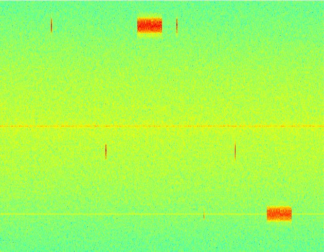
Fig. 1: Flow diagram of the node initialization sequence

       a) Modulation: We use GMSK modulation with a bit
rate of 200 kbps. Available frequencies are spaced 1 MHz
apart, every hop has a duration of 50 ms, including a guard         Fig. 2: Flow diagram of a point-to-point data transmission
time of 8 ms. Data transmission occurs in bursts of variable
lengths (but never exceeding one hop).
       b) Node addressing: Every node is dynamically assigned
a network address, which is used for point-to-point transmis-
sion. Upon activation, a node observes the spectrum to detect
other nodes (neighbourhood discovery). After a certain period
of time, the node assigns itself the lowest free network address
available. If no nodes are detected, it assigns itself address 1
(i.e., the lowest address possible).                                   Fig. 3: Example of a channel access by three nodes.
   Once a node has an address, it transmits a beacon packet
in random intervals, but with a fixed average repetition rate
(e.g. one beacon packet per 50 hops) on a hop set reserved for     available, and it is removed from the list of neighbours, as
broadcast signals (the broadcast channel). These beacons are       shown in Fig. 2.
used by new nodes to identify the available network addresses.        Fig. 3 shows an example of three nodes accessing four
   After identifying other nodes and synchronizing with the        channels in total. First, node 1 attempts to transmit to node
hopping sequence, a node waits a random time to avoid              2, receives a CTS signal and transmits. The same happens
simultaneous synchronisation with another new node.                between nodes 1 and 3. Nodes 3 and 2 also send out a beacon
   Fig. 1 illustrates the addressing and synchronisation se-       signal (BCN) on the broadcast channel (BCST).
quence.
       c) Point-to-point data transmission: Every node has its              III. W IRELESS N ETWORKS IN - THE - LOOP
own hop sequence for data transmission, which is defined              A method to speed up development time and remove
by its network address. When one nodes wants to transmit           the gap between simulation and implementation is Wireless
to another, it sends a request-to-send (RTS) packet to the         Networks in-the-loop. The principle is simple: Instead of
destination node. If this node is not occupied, it answers with    alternating between simulations (e.g. using Matlab) and testing
a clear-to-send (CTS) packet. The transmitting node can then       live implementations, a radio system is directly developed
transmit the data packets.                                         using a software radio framework. In order to transmit and
   If no CTS packet is received, it retries the process after a    receive, such radio systems are connected to some kind of
random duration which increases with every try. After a certain    RF hardware, which performs the necessary steps to convert
number of tries, the receiving node is assumed to be no longer     between passband and complex baseband signals (frequency
Fig. 5: The typical development cycle using wireless networks
in-the-loop
(a) Software Radio nodes operating with RF hardware works in-the-loop environment are:
1) Abstracting the hardware layer in software, which in-
cludes emulating the device drivers and distorting the
signal in the same way the hardware does.
2) Modelling the wireless propagation channels between
nodes, including fading and path loss.
3) Controlling the SR processes and connecting them either
to virtual or real RF hardware, depending on the mode
of operation.
A. Implementation details
For our implementation, we chose to limit the software
available for the nodes to GNU Radio and the hardware to
UHD-compatible1 devices. GNU Radio is a free software
library for developing software radio applications [6], and its
open source nature gives us great flexibility. Also, it is easily
portable to a large variety of platforms.
(b) Software Radio (SR) nodes operating in a virtual environment. A dispatch
and control process (DCP) controls the individual nodes.
Our implementation includes:
• Connectivity to UHD. In particular, virtual interfaces to
Fig. 4: The two modes of the wireless networks in-the-loop: the hardware are provided, which allow switching be-
Real and simulated environments tween virtual and real hardware from outside the software
radio node process.
• A subsystem to connect multiple SR nodes virtually in a
mixing, filtering, rate conversion etc.). The communication wave propagation model.
between the SR and the hardware usually consists of I/Q • A dispatch and control process (DCP), which controls the
samples as well as control signals, such as the choice of the individual nodes and connects them in the virtual wave
centre frequency, bandwidth or gain settings. propagation model when running in simulated mode.
A wireless networks in-the-loop system can understand • A simple channel sounding tool to measure channels in
these data flows between SR and hardware and redirect them real mode for further use in simulated mode.
to an internally processed wave propagation model. Here,
signals are passed between nodes digitally, including signal B. Developing SR-based networks
impairments caused by the hardware, such as I/Q imbalance So how can this method be used to develop radio systems?
or thermal noise, and of course the influence of the wireless The first step is to develop a prototype for a single node, which
channels, such as path loss and fading. is not difficult if an established SR framework such as GNU
Fig. 4 illustrates the principle. Either the nodes operate with Radio is utilized. During this step, all the standard tools of
attached hardware, or within the simulated environment. For software development, such as unit testing, can and should be
the individual nodes, it is irrelevant in which mode they are applied.
operating: From the software’s perspective, they receive and As soon as a first prototype is ready for a network operation
transmit I/Q samples, regardless if they were physically trans- test, it can be tested using the wave propagation model. First, a
mitted or not. The typical workflow with such a system would scenario is defined, which specifies the number of participating
be to quickly iterate between simulated and real measurements, nodes, their position (these might also be generated randomly),
thereby improving the quality of the SR node in every step. the type of fading channels between the nodes and sources of
Because there is only one code base to work on, there is no external interference.
friction when switching between simulation and live testing. 1 USRP Hardware Drivers, an open source driver suite for devices by Ettus
The three major challenges for developing a wireless net- Research LLC.317.0 MHz
316.0 MHz
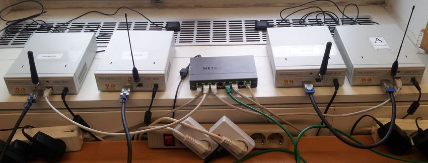
Fig. 6: The test setup for the first live testing, using four USRP
315.0 MHz
N210
To test the prototype, a supervising process dispatches 314.0 MHz
an instance of the SR node for every time it appears in
the scenario, as well as another process which connects the 0.0s 100.0 ms 200.0 ms 300.0 ms 400.0 ms 500.0 ms
individual nodes by simulated fading channels. This simulation
can be repeated with several different scenarios. Fig. 8: Visualization of data exchange between two nodes.
By logging relevant metrics such as packet loss, bit error
rate etc., the performance of the individual node can be
evaluated in a simulated environment. These results can then To prove the concept of our implementation, a specific
be used to further develop the SR implementation. scenario is repeated both in the simulation and over the air.
Once the network simulation works satisfactorily, we can Fig. 7 shows how the nodes are communicating with each
deploy real hardware and live-test the network. It is likely other (see Section II for a closer description).
that this test will expose new problems. Before returning to When using the USRPs, a fifth device is used to observe
the simulated environment, it is possible to perform channel the spectrum (see the waterfall diagram in Fig. 8). During
sounding measurements, such that the simulated measurements simulations, the spectrum can be observed directly from the
are similar to those in the real scenario. wave propagation model.
The key point is that the code base for the SR nodes stays The network behaves similarly in both cases. As an exam-
the same during all of these iterations. This eliminates any ple, the neighbourhood discovery takes the same amount of
friction typically involved when switching between simula- time regardless of the operation mode, which shows us that
tions and live measurements. Also, simulations and live tests the testing of the network aspect is functional.
both have their specific advantages and disadvantages, e.g., The packet error rates are different when switching between
simulations can easily produce many different, but repeatable the modes, though: In simulated mode, we have a packet error
scenarios, where as live tests are per definition realistic. Only rate below 1%, which increases to 2-5% in the live mode,
when the underlying code of the SR node is the same in both depending on how the transmitters are positioned relative to
tests can results from one be transferred to another. each other. This difference is to be expected: In our current
IV. C ASE S TUDY: D EVELOPING AND TESTING IN THE implementation, the hardware influences are not correctly
LOOP modelled yet, which means the signal reaching the individual
The frequency hopping ad hoc networks from Section II node is less distorted than in reality. By reconfiguring the
were used to test the current state of our wireless networks signal processing of the virtual RF hardware, this can be
in-the-loop implementation. In the first step, we created a changed to more accurately reflect the true values.
node with the specifications from Section II-A using GNU Now we know the simulation and the live testing results are
Radio. This prototype is kept very simple, but it includes comparable, we can start developing in the simulation mode
functionalities to test packet error rates, which we will use (since it requires less hardware), but can continue to switch
as a first performance metric. between modes in order to get more information about the
Our hardware test bed consists of four USRP N210, as can nodes true performance. In simulation mode, we can add nodes
be seen in Fig. 6, so first tests are run using four nodes to without having to purchase additional hardware, knowing that
be able to compare the results between simulation and live the results will still reflect reality.
testing.
V. C ONCLUSION
Due to the simplicity of the individual node, it is possible to
run four nodes in real time on one computer, which simplifies Wireless networks in-the-loop is a powerful tool for devel-
the testing. All USRPs are connected by Ethernet over a switch oping and testing SR-based networks. Using the example of
and can thus be controlled from a single machine. Also, the frequency hopping ad hoc networks, we could demonstrate the
switching between live tests and simulations is simple and capabilities of wireless networks in-the-loop and demonstrate
seamless. how it can be used to reduce development time.Fig. 7: Example for a data transmission between two nodes.
While our implementation still has some missing features, R EFERENCES
it is already able to show that network operation testing [1] J. Elsner, “Interference Mitigation in Frequency Hopping Ad Hoc
is possible, regardless of the mode. This allows developing Networks,” Forschungsberichte aus dem Institut für Nachrichtentechnik
nodes with a complex physical and network layer and produce des Karlsruher Instituts für Technologie, vol. 29, 2012. [Online].
Available: http://digbib.ubka.uni-karlsruhe.de/volltexte/1000031465
realistic test results, which could not be generated with other [2] J. Mo, H.-S. W. So, and J. Walrand, “Comparison of Multichannel MAC
tools which abstract the PHY layer of receivers when testing Protocols,” IEEE Transactions on Mobile Computing, vol. 7, no. 1, pp.
networks. 50–65, Jan. 2008.
[3] F. Baccelli and B. Blaszczyszyn, “Stochastic geometry and wireless
networks, volume 1+2: Theory and applications,” Foundations and Trends
in Networking, 2009.
[4] J. Mo, “Performance Modeling of Communication Networks with Markov
Chains,” Synthesis Lectures on Communication Networks, 2010.
[5] J. Elsner, M. Braun, S. Nagel, K. Nagaraj, and F. K. Jondral, “Wireless
Networks In-the-Loop: Software Radio as the Enabler,” Software Defined
Radio Forum Technical Conference, Washington DC, 2009.
[6] “GNU Radio website.” [Online]. Available: www.gnuradio.orgYou can also read