Design and analysis of bogie and coach of mass rapid transit (metro) for Nepal
←
→
Page content transcription
If your browser does not render page correctly, please read the page content below
Kathmandu University Journal of Science, Engineering and Technology, Vol. 15, No. 2, August 2021

       Design and analysis of bogie and coach of mass rapid transit
                            (metro) for Nepal
                             Parash Jung Karki * , Bikash Sharrf , Daniel Tuladhar , and Chiranjeevi Mahat

                           Department of Mechanical Engineering, Kathmandu University Dhulikhel, Nepal.

     Abstract
     Mass Rapid Transit (Metro) has become the ultimate solution for city transportation due to its various advantages including traffic issues solv-
     ing ability, emission free mode, comfortability, speed and efficiency. In developing countries like Nepal where people are deprived of proper
     transportation system, Metro railway can bring about lots of positive socio-economic changes. A lot of analysis regarding the technical aspects
     and designing process adapted throughout the globe has been done and the best suited design for the context of Nepal has been included in the
     paper. A Bogie is a chassis or framework carrying wheels attached to the train, serving as a modular subassembly of wheels and axles. Old bogies
     are cast models which are huge and bulky in its nature. In order to overcome the limitations of the existing FIAT bogie, a new bogie namely Y32
     Bogie is designed to equip with the coach. The coach with the longitudinal arrangements of seats is designed to accommodate the higher number
     of passengers. The design of the various bogie components is done following the procedures of machine design and various standards that suits
     the best for our context. The 3D-modeling of the bogie and the coach is performed in CREO PARAMETRIC 5.0. The design of bogie frame is then
     imported to ANSYS 19.2 for Finite Element Analysis. The analysis on stresses and maximum deformation induced in the bogie frame structure
     for different materials is performed and the comparison is made to find the best suited design. To achieve the Finite Element Analysis, the load
     criteria are considered from Indian Railway Standards.

     Keywords: ANSYS 19.2; FIAT Bogie; Y32 Bogie; Creo Parametric 5.0; FEA

1. Introduction

   A Mass Rapid Transit system is a transit system using trains of
high performance electrically powered rail cars operating in exclu-
sive rights-of-way, usually without grade crossings, with high plat-
form stations. Mass Rapid Transit help catalyze new economic and                                   Figure 1: Configuration of coaches.
employment opportunities by acting as nodes of development. The
mass rapid transit system is the need of the hours as it offers the
benefit of allowing larger number of people to travel from one area            2. Loadings and calculations
to the other area in the predetermined time. Nowadays, pollution
                                                                                  Two motor coach and two trailer coach is designed in Creo Para-
has become main concern for the Government as different ways
                                                                               metric 5.0 following specifications according to the Railway Board
are being explored to reduce the pollution problems. The provi-
                                                                               of India and its approximate mass is measured by assigning spec-
sion of MRTs as means of public transport offers great opportunity
                                                                               ified materials to all the components. The configuration of the
in combating the pollution issues. In contrasts to buses being used
                                                                               coaches is shown in Fig. 1. The maximum design speed of the
for public transport, MRTs offers clean and hygienic mode of trans-
                                                                               metro is 90 km/hr and operating speed is 70 km/hr [4].
port for commuting from place of residence to their place of work
                                                                                  Number of Motor Coach (MC) = 2
[1].
                                                                                  Number of Trailer Coach (TC) = 2
   A bogie is a structure underneath a railway vehicle body to                    Mass of motor coach = 63 tons
which axles and wheels are attached through bearings. The term                    Mass of trailer coach = 53 tons
“bogie” is used in British English, while a “wheel truck”, or sim-                Total Mass of Metro (Mmetro ) = 232 tons
ply “truck” is used in American English [2]. The outer shell of the               Weight of the metro (Wmetro ) = 255 tons
train/metro that carry the passenger or load within it is called
coaches. The overall part that lies on the bogie frame is also called          2.1. Power and numbers of motors required [5]
coaches. Depending on the feature and requirement the coaches
                                                                                  The tractive effort can be calculated by the following equations:
are of different types. Motor coach is a powered vehicle with
axles each equipped with a 3 phase asynchronous Traction Motor
                                                                                             Tractive effort (TE) =Fa ±Fg +Fr (Newton)
whereas Trailer coach is a non-powered coach. Generally, Trailer
coach is situated behind the motor coach [3].                                    Force required for Linear and Angular acceleration (Fa ) is given
                                                                               by;

   * Corresponding author. Email: parashjung54@gmail.com                                                Fa = 277.8 × We × a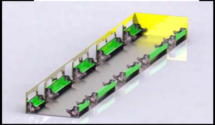
2                                                                  P. J. Karki et al.

    Where,

                                                                                        Tractive effort (TE) = Fa ± Fg + Fr = 181.58 kN
Accelerating weight (We ) = W eight
                                                                                Now, the power required to run the metro at a speed of 90 km/hr
                              + W eight × Rotational mass in %
                                                                              with acceleration of 2.25 m/s is given by the equation;
    We = 272.85 tonne
                                                                               Power (W ) = T ractive ef f ort (N)×Speed (m/s) = 4539.495 kW
                           Velocity (km/hr)
        Acceleration (a) =                  = 2.25 km/hr sec                      The required power is higher (i.e. 4539.495 KW) because the trac-
                              Time (sec)
                                                                               tive force is higher initially but when the train gets speed the trac-
                                                                               tive force get decreased resulting in the low amount of power con-
                        Fa = 170544.8925 N
                                                                               sumption.
    Force due to Gradient and Curve Resistance (Fg ) is given by                  The above power is generated by motor situated in bogie.
                                                                                  Number of motor coach (MC) = 2
                   Fg = ± 98.1 × W × G + Rcurve                                   Number of motor in each bogie = 2 (One motor per axle)
                                                                                  Number of bogie in single coach = 2
    W is the weight of the train in ton.

                                           Elevation                                       T otal number of motor in a single coach
           Gradient (G) = sin θ =
                                    Distance along the train
  θ is the angle of slope.
                                                                                = N umber of bogie per coach × N umber of motor in each bogie
  For the straight and level track condition the gradient force can
be neglected since the value of gradient is zero.                               =4

                                              1750                                             T otal number of motor in train
        Degree of curvature =
                                  Radius of curvature in metres
    Assuming the radius of the curvature to be 300 m.                               = N umber of coach × N umber of motor in one coach
                                                                                    =8
                   Degree of curvature = 5.833
                                                                                 Therefore, the above power is distributed along the eight mo-
    The curve resistance is given by
                                                                               tors.
    Rcurve

                                                                                                                  Total power required
        0.4 × Degree of curvature × g × M asstrain (tonne)                              P ower of each motor =
    =                                                      kN                                                    Total number of motors
                              1000
                                                                                                               = 567.43 kW = 760.94 hp
                                                    = 5.31 kN
                                                                                 Hence, to drive a metro train including all passenger and train
    Therefore,
                                                                              weight we will need eight numbers of motor each of 765 hp.
                                                                                 For the further design of axle and other components of the bo-
             Fg = ± 98.1 × W × G + Rcurve = 5.31 kN
                                                                              gie we need the torque transmitted by the motors which can be
    Tractive force to overcome the Train Resistance (Fr ) is given by         obtained by using equation;

                             Fr = W × r                                                                             T.E × Dwheel
                                                                               T orue developed by motors T =                    = 28195.622 Nm
    W is the weight of the train in Newton.                                                                          2×η×β
    r is the specific train resistance in N/tonne.
                                                                                  Where,
    Train resistance using W.J. Davis formula:
                                                                                  η is the transmission efficiency assumed to be 92%.
                                                                                  β is gear ratio assumed to be 3.5.
    T rain resistance (R) =                                                       T is the torque developed by all motors.

                             = A + BV + CV 2
                             1.2 + 0.001 × 100 + 0.0001 × 1002                 T orue developed by a single motor, Tone,motor = 3524.45 Nm

                                                                               2.2. Forces for FIAT and Y32 Bogie Frame [6]
                 Train resistance (R) = 29 kg/tonne                               Vertical force on bogie frame is given by;

                                                                                                        1.4 × g(MV − 2m+ )
                                                                                                  FY =
          Specif ic train resistance (r) = 22.45 N /tonne                                                          2
                                                                                  Transverse force on bogie frame is given by;
    Therefore,
                                                                                                                    (MV + C1 ) g
                           Fr = 5724.75 N                                                      FZ = 2 × (104 +                   )
                                                                                                                      3na nb
    Finally, the total tractive force can be calculated using equation            Longitudinal force on bogie frame is given by;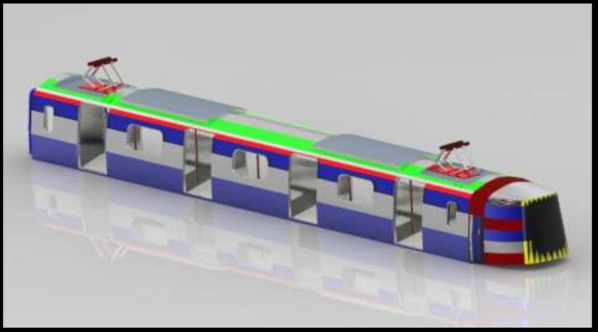
Kathmandu University Journal of Science, Engineering and Technology, Vol. 15, No. 2, August 2021                             3

       Table 1: Load comparison for FIAT and Y32 bogie frame.

 Force type             Force Magnitude (kN)
                        FIAT Bogie Frame              Y32 Bogie Frame
 Vertical Force         274                           293
 Transversal Force      106                           114
 Longitudinal force     25.75                         28
 Impact Force           2575.125                      2803.3

                                                                                                        Figure 2: Load on bearing and gear.
                                      MV g
                         FX   = 0.1 ×
                                       na
  Impact force on bogie frame is given by;
                                                                                                                                         π
                                                                                          Equivalent twisting moment, Te =                  × τ × d3shaft
                                                                                                                                         16
                   Impact f orce = 5g × MV
                                                                                    Where, τ is maximum shear stress theory = 60 Mpa .Then, we
  For FIAT Bogie Frame;
                                                                                  get;
  Mass of locomotive in running order (MV ) = 52500 kg
  Mass of bogie (m+ ) = 6300 kg                                                                               dshaft = 167.68 mm
  Acceleration due to gravity (g) = 9.81 m/s2
  Number of axles (na ) = 2                                                         Case II: Size of the shaft when subjected to gradually applied
  Number of bogies (nb ) = 2                                                      load;
  Mass of the driver (C1 ) = 85 kg                                                  Equivalent twisting moment is given by;
  For Y32 Bogie Frame;
                                                                                                √
  Mass of locomotive in running order (MV ) = 57152.6 kg
                                                                                         Te =       (Km × M )2 + (Kt × T )2 = 83.208 × 10⁶ Nmm
  Mass of bogie (m+ ) = 7257.48 kg
  Acceleration due to gravity (g) = 9.81 m/s2                                        Km is the combined shock and fatigue factor for bending mo-
  Number of axles (na ) = 2                                                       ment whereas Kt is the combined shock and fatigue factor for tor-
  Number of bogies (nb ) = 2                                                      sion [Values are taken from design data book].
  Mass of the driver (C1 ) = 85 kg                                                   Since,
  From Table 1, it can be observed that all the forces acting on
the y32 bogie frame is higher than flat bogie frame because both                                                      π
                                                                                                              Te =       × τ × d3
the moving mass and locomotive mass of the y32 bogie is higher.                                                       16
The load bearing capacity of y32 bogie is much higher than the flat                  So, d = 191.86 mm
bogie.                                                                               Equivalent bending moment
                                                                                                         √     is given by;
                                                                                    Me = 12 [Km ×M + (Km × M )2 + (Kt × T )2 ] = 83.16 ×
2.3. Axle load and diameter [7]                                                      6
                                                                                  10 Nmm
  Case I: Shafts Subjected to Combined Twisting Moment and                          Diameter of the shaft is given by;
Bending Moment.
                                                                                                                      π
  The diameter of the gear (attached to the motor) is assumed to                                             Me =        × σb × d3
                                                                                                                      32
be 100 mm. In above calculation, we the gear ratio of 3.5. So, the
diameter of the gear (attached to the axle) is 350 mm.
                                                                                                                 d = 211.13 mm
  Speed of the driven gear (pinion) is given by:
                                                                                    The maximum value is taken, so the diameter of the shaft will be
                           60 × v                                                 211.13 mm. [Standard diameter of 220 mm is taken]
              Npinion   =           = 1364.18 rpm
                          2πrpinion
                                                                                  2.4. Brake Design [7]
                                                P × 60                    The main condition imposed is that braking forces at the wheel-
Torque transmitted by pinion (Tpinion ) =                = 3.97×10⁶ Nmm
                                               2πNpinion               rail contact surface Fb, max must not exceed the wheel-rail adhesion
                                                                       force Fa , for designing purposes considered in normal conditions:

                                              2Tpinion                                                            Fb,max ≤ Fa
T angential f orce on the pinion, Ft =                 = 22.697 ×10⁶ N
                                              Dpinion
                                                                                    Considering a vehicle having Wv weight being equipped with n
   Maximum bending moment of a simply supported shaft carrying                    brake shoes;
a central load (Fig. 2) is given by;
                                                                                                                   ∑
                                                                                                                   n

                    W ×L                                                                               Fb,max =           (µs . Psi ) ≤ µa .Wv
              M=           = 55.41 × 10⁶ Nmm                                                                        i=1
                       4
                                                                                     Respectively with n brake discs;
  Equivalent twisting moment is given by;
                                                                                                            ∑
                  √                                                                                4.µd . rm n i=1 . Pd,i )
           Te =    (M 2 + T 2 ) = 55.55 × 10⁶ Nmm                                                                           ≤ µa .Wv
                                                                                                            DO
  The diameter of the axle can be calculated by using design data                    Where,
book.                                                                                µa Is the wheel/rail adhesion coefficient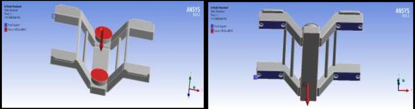
4                                                                  P. J. Karki et al.

   Ps and Pd are the clamping force on a brake shoe, and pad re-
spectively
   µs And µd the friction coefficient between brake shoes and wheel
tread and brake pad and disc respectively,
   The wheel diameter (Do =300 mm) and rm = 0.15 mm, the
medium friction radius.
   In the case of plastic brake shoes the friction coefficient is about
0.25, while for brake pads is about 0.35. Here, µs = 0.25 and µd =
0.35
   Using equation to get clamping force by pad, Pd ;
                             ∑
                   4.µd . rm n i=1 . Pd,i )
                                            = µa .Wv
                             DO

                    Pd = 7354.98 N by each brake
   In practical calculus, for the friction coefficient between cast
iron brake shoes and wheel tread there are recommended differ-                          Figure 3: CAD model of exterior of coach.
ent empirical relations, determined by experiments, depending on
most important influencing factors, meaning mainly the running
speed V [km/h], the applied forces on a break shoe ps [kN] or the
surface contact pressure ps [ [N/mm2 ].
   Using UIC formula,
                               10            875
                                  .V + 100    g
                                                 .ps + 100
          µs (V, ps ) = 0.49 3.6
                             35              2860
                              3.6
                                  .V + 100    g
                                                  .ps + 100
    We get,

       Surf ace contact pressure (ps ) = 0.1291 N /mm2
    Using Karvatzki formula;
                                             16
                                  V + 100    g
                                                .Ps + 100
              µs (V, Ps ) = 0.6              86
                                  5V + 100    g
                                                .Ps + 100

       Applied f orce on the brake shoe (P s ) = 2306.08 N

3. CAD design of coach, its interiors and bogie                                         Figure 4: CAD model of interior of coach.
   The exterior and the interior of a coach are shown in Fig. 3 and
Fig. 4 respectively which are designed using Creo Parametric 5.0.
The design of inner aesthetics of a coach refers to the arrangements
of seats and the optimization of space to accommodate the maxi-
mum number of passengers during the peak traffic hours. The in-
teriors of coach has been designed based on the fact that the floor
has a total area of 64 m2 . The maximum number of passengers that
a coach can accommodate is 90. In order to maximize the passen-
ger carrying capacity, longitudinal seating arrangement has been
adopted. Criteria for the calculation of standing passengers are 1
person per square meter of standing floor area in normal state and
2 persons per square meter in crush state of peak hour. The CAD
model of bogie, Fig. 5 has been designed as per the calculations and
standards followed by Indian Railways.

4. Static analysis of the bogie frame
   Bogie frame is a chassis carrying wheels, suspension system,
brakes and attached under the railway vehicles for running. Gener-
ally two pieces of bogies used for one passenger coach and a railway
vehicle consists of several coaches. Bogies are critical components
of a railway vehicle because of being running components. In this
study the static structural analysis of Y32 bogie is performed under                       Figure 5: CAD model of Y32 bogie.
two different loading conditions for different materials and the re-
sults are interpreted.
   The static structural analysis of the bogie frame involved the fol-
lowing steps: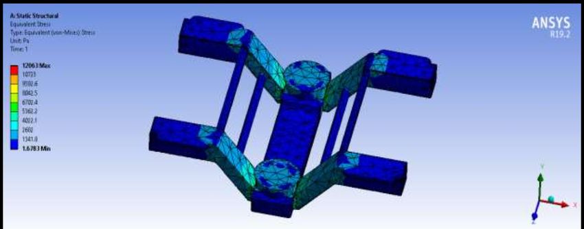
Kathmandu University Journal of Science, Engineering and Technology, Vol. 15, No. 2, August 2021 5
Table 3: Loads on bogie frame in minimum loading condition.
Particulars Quantity Units
Tare mass of a Coach 58.05 Tonnes
Tare Weight of a Coach 580500 N
Total Load on a Bogie Frame 290250 N
Table 4: Material properties.
Figure 6: Meshed model of bogie frame.
Material Density Young’s Tensile Tensile
(Kg/m3 ) Modu- Yield Ulti-
Table 2: Loads on bogie frame in maximum loading condition.
lus Strength mate
(Pa) (Pa) Strength
Particulars Quantity Units (Pa)
Total Mass of a Coach 63 Tonnes Cast 7820 2.03×10¹¹ 3.49×10⁸ 5.05×10⁸
Total Weight of a Coach 630000 N Steel
Total Load on a Bogie Frame 315000 N Low 7850 2.1×10¹¹ 3.29×10⁸ 4.4×10⁸
Carbon
Steel
4.1. Meshing of the bogie frame using Ansys workbench
The model of the bogie frame is prepared using Creo Parametric 4.4. Material selection
5.0. All the dimensions and geometric properties of Y32 bogie is
modelled in the software. The model is then imported to the Ansys The commonly used materials for the manufacture of bogie
Workbench and meshed as shown in Fig. 6. frame are cast steel and low carbon steel. The analysis is performed
under the above mentioned materials under different loading con-
4.2. Applying boundary conditions ditions and the results are obtained. The materials properties for
all the materials are tabulated in Table 2.
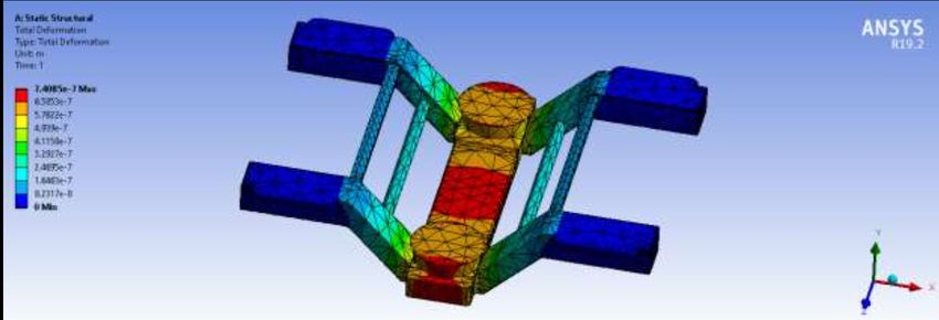
The four ends of the bogie frame are fixed. Boundary conditions After adding the material properties, the results of total defor-
are applied with two different loading conditions as shown in Fig. mation for cast steel under maximum and minimum loading condi-
7. The total load acting on the bogie frame is divided into two half tions are simulated as shown in Fig. 8 and Fig. 9 respectively. Sim-
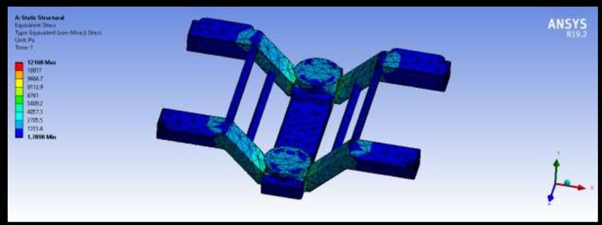
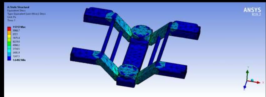
and applied on the either end of the secondary suspension. ilarly, Fig. 10 and Fig. 11 depict the results of equivalent stresses
for cast steel under maximum and minimum loading conditions re-
4.3. Loading conditions spectively. The simulated results of total deformation for low car-
bon steel under maximum and minimum loading conditions are
Two different loading conditions incur during static analysis of simulated as shown in Fig. 12 and Fig. 13. Fig. 14 illustrates the
a bogie frame. The minimum loading condition occurs when the result of equivalent stresses for low carbon steel under maximum
car body or the coach is empty. The maximum loading condition loading condition and Fig. 15 illustrates the result of equivalent
occurs when the coach is under crush loading or when the coach stresses for low carbon steel under minimum loading condition.
is full with its maximum limit of passengers. Since a single coach
consists of two bogies, the total load is divided into two halves and 4.5. Static structural analysis
applied on the bogie frames. The approximate load of the assembly
of bogie and coach is obtained by assigning the specific materials 5. Results and discussion
to the overall assembly in Creo Parametric 5.0.
Table 5 shows the tabulated results of the two tests conducted on
Tare mass of the coach = 58.05 Tonnes
same bogie frame but with different materials and different load-
Average mass of a passenger = 55 Kg ing conditions. Ansys result for the static structural loading condi-
Maximum permissible number of passengers = 90 tion for all the materials shows that the maximum induced stress
Total mass of passengers in maximum loading condition = 4950
Kg Table 5: Total deformation and equivalent stress for ccast steel and low car-
Total weight of passengers in maximum loading condition = bon steel under different loading conditions.
49500 N
Materials Minimum Maximum
4.3.1. Case I (Maximum Loading Condition) Loading Loading
The maximum load is equal to summation of the tare mass of Condition Condition
the coach and its pay mass. The loads acting on bogie frame in Total De- Equivalent Total Equivalent
maximum loading condition are calculated and tabulated in Table formation Stress (Pa) Defor- Stress
2. (m) mation (Pa)
(m)
4.3.2. Case II (Minimum Loading Condition) Cast 7.408×10⁻⁷ 11212 8.0402×10⁻⁷ 12168
Steel
The minimum load is equal to the tare mass of the coach or the
Low 7.146×10⁻⁷ 11115 7.755×10⁻⁷ 12063
weight of the coach excluding the passengers. The loads acting on
Carbon
bogie frame in minimum loading condition are calculated and tab-
Steel
ulated in Table 3.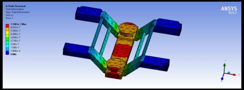
6                                                                    P. J. Karki et al.

                                                    Figure 7: Boundary conditions of bogie frame.

Figure 8: Total deformation of bogie frame for cast steel under minimum
          loading condition.                                                     Figure 12: Total deformation of bogie frame for low carbon steel under
                                                                                            minimum loading condition.

Figure 9: Total deformation of bogie frame for cast steel under maximum          Figure 13: Total deformation of bogie frame for low carbon steel under
          loading condition.                                                                maximum loading condition.

Figure 10: Equivalent stress of bogie frame for cast steel under minimum         Figure 14: Equivalent stress of bogie frame for low carbon steel under min-
           loading condition.                                                               imum loading condition.

Figure 11: Equivalent stress of bogie frame for cast steel under maximum         Figure 15: Equivalent stress of bogie frame for low carbon steel under max-
           loading condition.                                                               imum loading condition.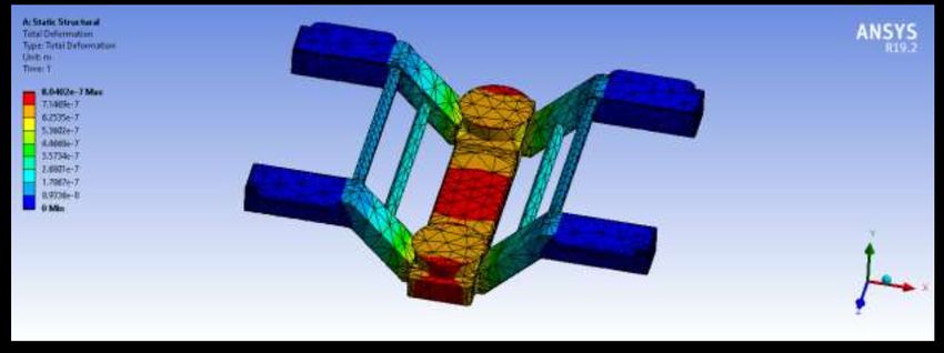
Kathmandu University Journal of Science, Engineering and Technology, Vol. 15, No. 2, August 2021                     7

is lesser than its tensile yield strength. The total deformation for             References
Cast Steel is higher than that of Low Carbon Steel in both the load-
                                                                                 [1] Fjellstrom K & Wright L, Sustainable Transport: A Sourcebook for
ing conditions. The value of total deformation in all the cases is
                                                                                     Policy Makers in Developing Cities, In: Transport Policy Advice.
negligible. So, the design of the bogie frame is considered to be
safe for both the materials.                                                     [2] Volume I, In: Railway Technical Handbook, SKF Group, Sweden
                                                                                     (2011).
6. Conclusion                                                                    [3] Introductory Handbook on Train, (2018).
  All the design and calculations of this research are done based
                                                                                 [4] Standarization and Indigenisation of Metro Railways, Systems
on the Indian Railway Standards as various critical factors includ-
                                                                                     and Subsystems, (2013).
ing traffic conditions, land topography and other socio-economic
aspects of Nepal are relatable to that of India. The research reveals            [5] Chandra S & Agrawal M M, Railway Engineering, Second., Oxford
the essential elements to be considered while designing the compo-                   University Press (2013).
nents of metro. This research can be used as a reference for further
research regarding the various prospects of metro in our country.                [6] Volume II, In: Railway Technical Handbook, SKF Group (2012).
The similar methodology can be followed for performing structural
analysis on other components of the bogie.                                       [7] Khurmi R S & Gupta J K, A Textbook of Machine Design, Four-
                                                                                     teenth., Eurasia Publishing House Pvt. Ltd. (2005).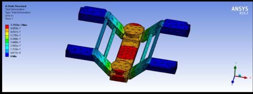
You can also read