Intact Muscle Chamber - USER'S GUIDE - Manual Revision 1.0 June 2017 - IonOptix
←
→
Page content transcription
If your browser does not render page correctly, please read the page content below
USER'S GUIDE

                  Intact Muscle
                    Chamber

Manual Revision 1.0
June 2017

Intact Muscle Chamber   Introduction • 1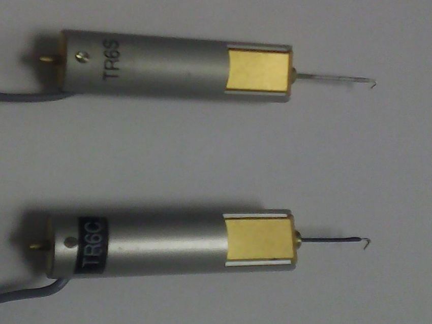
Copyright 2017 IonOptix, all rights reserved.

Disclaimer: This is an electrical device. There is an inherent risk of electrical shock if used improperly. Please
take the necessary precautionary measures that are common place for any electrical device. It is solely
intended for the applications outlined in this document. The manufacturer is not liable for any misuse, or any
injury incurred because of misuse.

Always unplug device before checking fuse!

Disclaimer: This product is intended for research purposes only. It is not certified for clinical applications
(including diagnostic purposes). Use of this product in uncertified applications is in violation of FDA
regulations.

2 • Introduction                       Intact Muscle Chamber
Contents
1     Introduction ...................................................................................................................................................4
2     Intact Muscle Chamber - Unit Description ....................................................................................................4
    2.1    Features .................................................................................................................................................4
    2.2    Diagram .................................................................................................................................................5
3     Intact Muscle Chamber - Components .........................................................................................................6
    3.1    Baseplate, pedestals, and housings ......................................................................................................6
    3.2    Micromanipulator and adapter plate ......................................................................................................9
    3.3    Piezo motor and hook extension (aka beak) ...................................................................................... 11
    3.4    Force transducers ............................................................................................................................... 12
    3.5    Stimulation wires................................................................................................................................. 13
    3.6    Platinum hooks ................................................................................................................................... 14
    3.7    Platinum omega-clips ......................................................................................................................... 15
    3.8    Chamber and fluid flow ....................................................................................................................... 17
4     Packaged and Shipped .............................................................................................................................. 19
    4.1    Baseplate ............................................................................................................................................ 19
    4.2    Beak and accessories......................................................................................................................... 20
    4.3    Chamber and fluid control. ................................................................................................................. 20
    4.4    Cable for electrical stimulation. ........................................................................................................... 21
5     Required Accessories ................................................................................................................................ 22
    5.1    Magnifying glasses for microdissection and loading muscle .............................................................. 22
    5.2    Accessories required prior to any training visit ................................................................................... 23
6     Appendix: Helpful Experimental Protocol .................................................................................................. 24
    6.1    Loading a muscle sample (size ~mouse papillary muscle) with AM-form of fluorescent dye. ........... 24

Intact Muscle Chamber                                         Introduction • 3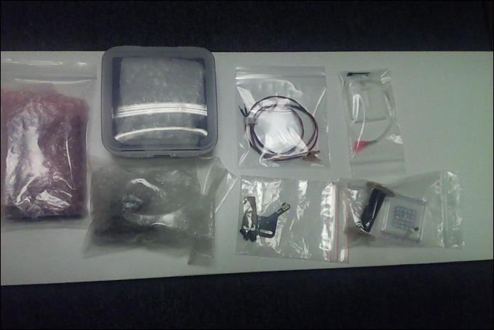
1       Introduction
This equipment is useful for simultaneous recording of contractile force and Ca2+ handling characteristics in
intact muscle strips with dimensions mm-cm. To call the muscle ‘intact’ means that its membrane is excitable,
and electrical stimulation will elicit Ca2+ release into the cytosol of the muscle cells thus leading to force
production and muscle contraction.
The most notable components are (i) the force transducer, (ii) the length controller and (iii) the chamber,
which allows for submersion of the muscle in a Ca2+-rich solution.

2       Intact Muscle Chamber - Unit Description

2.1     Features
    2.1.1 Muscle types
This unit is designed to be used for intact, excitable muscles up to ~2 cm in length:

•       Cardiac papillary muscle of many species (mouse, rat, rabbit, cat, dog, pig)
•       Cardiac endocardial strips or trabeculae (mouse, rat, rabbit, cat, dog, pig, human)
•       Cardiac epicardial strips (mouse, rat, rabbit, cat, dog, pig, human)
•       Skeletal muscles, e.g., soleus, extensor digitorum longus (EDL), gastrocnemius, cremaster (mouse,
        rat)

    2.1.2 Stimulation through platinum clips/electrodes
Stimulation of the muscle sample is elicited by electrical current passing directly through the muscle sample,
therefore obviating the possibility of any reduced stimulation as occurs with bath electrodes. This is
accomplished using platinum clips to connect the muscle to platinum electrodes that have been incorporated
as part of the force transducer and length controller.

    2.1.3 Simultaneous force and Ca2+ recordings
A clear cover slip forms the bottom of the chamber and, if placed on an inverted microscope fitted with a long
working distance objective, allows fluorescence light detection. It should be noted that the muscle will be
placed 1-2 mm above the surface of the cover slip, therefore the objective should have a working distance of
greater than ~1.5 mm.

4 • Introduction                      Intact Muscle Chamber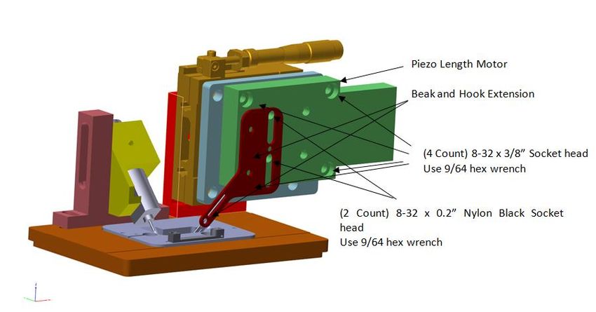
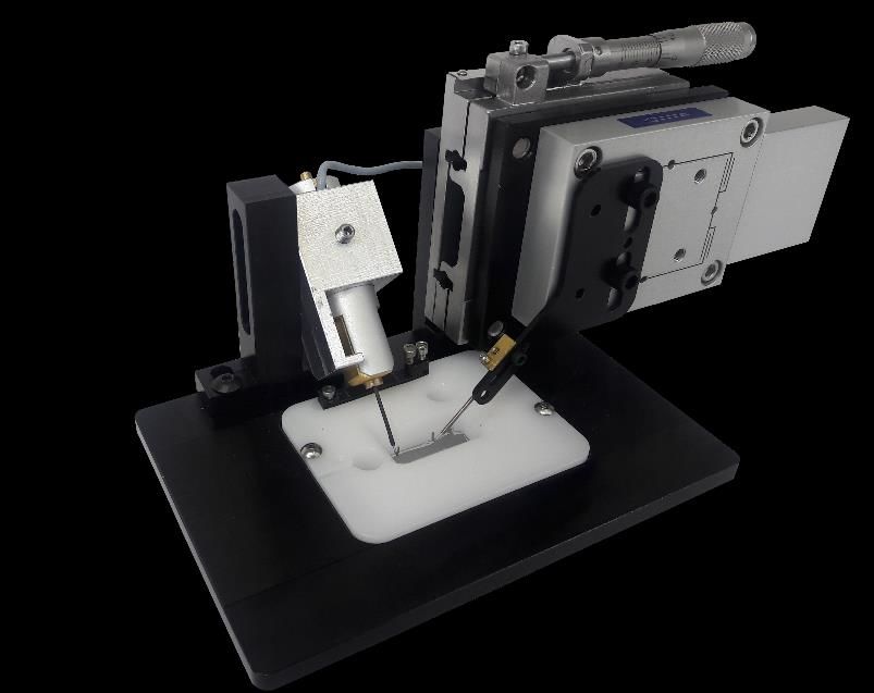
2.2    Diagram

Intact Muscle Chamber   Intact Muscle Chamber - Unit Description • 5
3       Intact Muscle Chamber - Components

3.1     Baseplate, Pedestals, and Housings

 3.1.1 Pieces
The baseplate is a thin (
3.1.3 Diagrams and Assembly
  3.1.3.1    Baseplate, pins and pedestal for length controller:

Intact Muscle Chamber   Intact Muscle Chamber - Components • 7

3.1.3.2    Assembly of pedestal and housing for force transducer (only Güth-style
               force transducers)

8 • Intact Muscle Chamber - ComponentsIntact Muscle Chamber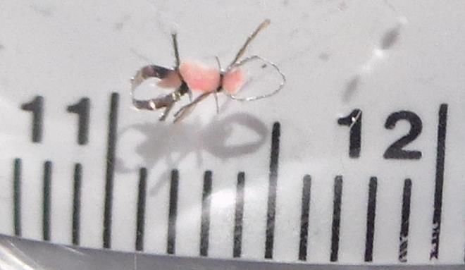
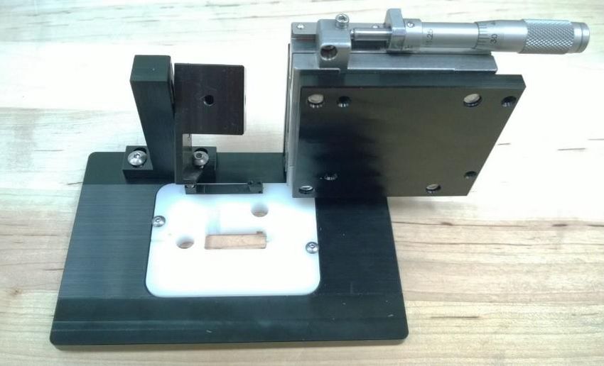
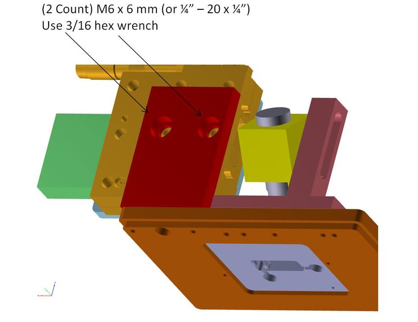
3.2       Micromanipulator and Adapter Plate

 3.2.1 Pieces
The manual micromanipulator is used for coarse movement of the length control with a range of 25 mm or ~1
inch. This coarse micromanipulator is attached to a pedestal anchored to the baseplate. Fine length control is
achieved with a piezo motor with a range of 50 microns.

 3.2.2 Rationales and options
As muscle lengths widely vary, a manual micromanipulator is important to position the hooks to accommodate
muscle sample length.
                                                                                 Manual Micromanipulator
 3.2.3 Diagrams                                                                  Coarse Length Controller
      •    Overview of the pieces and their placement:
                                                                                 Adapter Plate

                                                                                 Piezo Length Motor

                                                    spanner nut         Note: If the hashmarks are not visible
                                                                        here, as demonstrated in this photo,
                                                                        then you will need to loosen the spanner
                                                                        nut and turn the sleeve so the
                                                                        hashmarks are showing toward the
                                                                        user, i.e., toward the front of the
                                                                        apparatus. You should then tighten the
                                                                        spanner nut when done.

Intact Muscle Chamber       Intact Muscle Chamber - Components • 9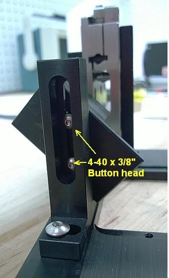
•   First put the Adapter Plate on the Micromanipulator:

     •   Then put the Micromanipulator onto the Pedestal:

10 • Intact Muscle Chamber - ComponentsIntact Muscle Chamber
3.3 Piezo Motor and Hook Extension (aka Beak) 3.3.1 Pieces The manual micromanipulator is used for coarse movement of the length control with a range of 25 mm or ~1 inch. This coarse micromanipulator is attached to a pedestal anchored to the baseplate. Fine length control is achieved with a piezo motor with a range of 50 microns. 3.3.2 Rationales and options When it is necessary to change the muscle length with high precision, a piezo motor is needed. A standard beak holder can substitute the piezo motor if high precision length control is not necessary. 3.3.3 Diagrams This is what the beak looks like with the tubing/hook attached. The red electrode from the MyoPacer should be attached to the button head screw, which is in electrical conductance with the platinum hook. Intact Muscle Chamber Intact Muscle Chamber - Components • 11
3.4     Force Transducers

 3.4.1 Pieces and Procedure for Assembly
The force transducers (TR6C – carbon rod lever and TR6S – stainless steel lever) are already assembled
except for any extension of the lever and the platinum hooks. The force transducer slips into its holder shown
in the diagram below.
IMPORTANT: Make sure the hook will be oriented such that a pull on the hook will be recorded as a positive
deflection by the force transducer!
Note also that the sheath around the force transducer is electrically insulated! No metal portion of the force
transducer should be in contract with the aluminum holder.

 3.4.2 Rationales and options
The force transducers (TR6C – carbon rod lever and TR6S – stainless steel lever) we use for this unit are
made by Dr. Konrad Güth at Myotronic, Heidelberg, Germany. Dr. Güth is a bit of legend in the muscle
physiology world. He is a brilliant experimentalist and developed many of the techniques and instruments
used in the field.
His force transducer is especially impressive for two reasons. First, it is based on detecting the deflection of a
mechanical lever using an LED light source and light sensor. It is simple, and also is electrically isolated from
the lever, which can now be used to pass current for stimulation of the muscle sample. Second, this design is
robust, meaning the force transducer is difficult to physically break. That is an important feature after you
consider that the experimentalist must load the muscle sample delicately.

 3.4.3 Diagrams

12 • Intact Muscle Chamber - ComponentsIntact Muscle Chamber
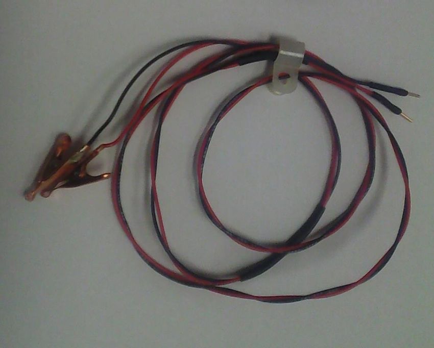
3.5     Stimulation Wires

 3.5.1 Pieces
The stimulation wires are simple wires that connect the MyoPacer to the platinum hooks. The connections at
the hooks, however, are different on purpose. One is connected to the hook on the length motor by a simple
Y-terminal. The other is connected to the force transducer by a modified alligator clip.

 3.5.2 Rationales and options
It is important that the ground wire be connected to the force transducer to prevent ground loops. That is why
the ground wire is terminated with an alligator clip that is shaped to fit the extension out the back of the Güth
transducer. The alligator clip allows for fast disconnect. The Y-terminal is used on the other end also allows
for relatively fast disconnect once the set screw has been loosened.

 3.5.3 Diagrams

Please note that the black wire should be connected to the ground electrode of the MyoPacer.

Intact Muscle Chamber       Intact Muscle Chamber - Components • 13
3.6     Platinum Hooks

 3.6.1 Pieces and Procedure for Assembly
Platinum rods can be easily cut and bent to shape. We use two different diameters of Pt rod: 0.020” (508
micron) and 0.023” (584 micron) depending on the receptacle. The rod is cut to ~15 mm long and bent at
135° angle so that a 2 mm portion of the rod will point straight up when placed in its receptacle. Looks like a
shepherd’s crook or a check mark (✓).

IMPORTANT: If preparing a force transducer, make sure the hook will be oriented such that a pull on the
hook will be recorded as a positive deflection by the force transducer!
The heat shrink tubing covers the boundary between platinum rod and stainless steel tubing.

 3.6.2 Rationales and options
Platinum is highly conductive, resistant to corrosion, resistant to electrolysis, and is biologically inert.
Considering that Pt is still rather soft compared to other very hard metals, like Tungsten (W) or stainless steel,
the Pt hook is relatively thick, usually 500-600 microns in diameter, to maintain a stiff connection.

 3.6.3 Diagrams

This rod is used as the hook extension of the length motor and also used as the lever arm in the TR6 S.

14 • Intact Muscle Chamber - ComponentsIntact Muscle Chamber
3.7     Platinum Omega-clips

 3.7.1 Pieces and Procedure for Assembly
Platinum foil can be easily cut and bent to shape. The Pt foil is only 0.001”-0.002” (25-50 micron) thick and
soft enough that it can be cut with ordinary scissors or with a scalpel blade. The dimension of the
rectangularly cut piece is approximately 0.5-1 mm wide and 5-8 mm long, depending on the muscle width
expected (thicker muscle, wider cut). This foil is then bent in half and shaped to look something like the Greek
letter omega, Ω, including the feet at the bottom. These Pt clips are relatively expensive and are meant to be
reused.
One end of the muscle sample will be placed between the feet of the omega, and ~7-O or similarly sized
suture is then used to hold the muscle in place relative to the clip. The loop at the top of the omega clip will
slip over the Pt hooks attached to the force transducer and length controller.
Customers should receive two pre-made clips and a strip of Pt foil 100 mm long. That should be enough for at
least 20 additional omega clips. See Packaged section.

 3.7.2 Rationales and options
Platinum is highly conductive, resistant to corrosion, resistant to electrolysis, and biologically inert. Therefore,
Pt will provide electrical contact while not interfering with the bathing solution or muscle preparation.
Copper (Cu), on the other hand, is highly toxic to muscle and cannot be used. Other metals, such as Al, Fe
(or stainless steel), Zn, Ag, etc, do not possess all four necessary properties. Gold (Au) may be the only metal
that is close to Pt in property performance. However, Pt is about 2x stiffer than Au, and therefore works better
than Au to provide a stiff mechanical connection between muscle and instrument.

Intact Muscle Chamber        Intact Muscle Chamber - Components • 15
3.7.3 Diagrams
Prepared Omega Clips, 0.001” thick, ~0.7 mm wide, ~4 mm long.
Curved to form omega shape, Ω, including feet. Now ~1.5 mm long, see photo below.

3.8

16 • Intact Muscle Chamber - ComponentsIntact Muscle Chamber
3.8     Chamber and Fluid flow

 3.8.1 Pieces and Procedure for Assembly
Chamber insert is made of delrin and fits into the opening of the baseplate. The chamber features one main
rectangular chamber, where the sample will be examined, and two circular side chambers, which enable
smooth fluid flow.
A no. 1 thickness coverslip (43 mm x 50 mm) is glued (silicon glue) onto the bottom of the chamber as shown
below. Aspirator height adjuster is screwed onto the ??
Hypodermic stainless steel tubing (20 G, 1 inch long) can be bent to dip into the side chambers and allow for
fluid flow.
Tygon tubing, 1/32” ID, 3/32” OD, 1/32 wall is good for fitting the 18-20 G tubing into a fluid flow circuit.
Blunt hypodermic stainless steel needle (18-20 G, 1 inch long) can be used to allow fluid flow with lure fitting.

 3.8.2 Rationales and options
The nice thing about having this plastic insert is this: it can be easily replaced. We don’t expect it to break, but
we do expect the coverslip to possibly break and/or there be a need for a different shape chamber. Therefore,
having an insert makes for easy redesign and fast chamber replacement. Skinned muscle experiments, for
example, do not require the side circular chamber for fluid flow. So, a version without the side chambers can
fit into the same baseplate.

 3.8.3 Diagrams

                                                     Caption?

Intact Muscle Chamber        Intact Muscle Chamber - Components • 17
¼” Button head Use 1/16 hex wrench 18 • Intact Muscle Chamber - ComponentsIntact Muscle Chamber
4      Packaged and Shipped

4.1    Baseplate

Pedestal and holder for Force Transducer   Pedestal, micromanipulator, and adapter
                                                 plate for Length Motor

Intact Muscle Chamber            Packaged and Shipped • 19
4.2 Beak and accessories. Note that the platinum hook is shipped in the cardboard marked ‘fragile’. 4.3 Chamber and fluid control. Note, during assembly put the bent tubes in place before attaching to the tygon tubing. 20 • Packaged and Shipped Intact Muscle Chamber
4.4     Cable for electrical stimulation.
Note that the thumb screw and cable tie allow for creating a cable stand off as part of the length motor
assembly

Intact Muscle Chamber              Packaged and Shipped • 21
5         Required Accessories

      •    Magnifying glasses for loading muscle (see below)
      •    Bathing solutions for intact muscle
      •    Inline heater
      •    Flexible polystyrene tubing for delivery of solutions and gases
      •    Bubbling stone, gases, and vacuum grease
      •    Peristaltic pump
      •    Small dishes for dissection and storage of tissue
      •    Cooled dissection plate
      •    Peltier circulator for cooled dissection plate
      •    Dissection tools
      •    Fluorescent dyes

5.1       Magnifying glasses for microdissection and loading muscle
Recommend Standard 1.75X magnification with 14” focal length.
Illumination on magnifier is not necessary if there is sufficient lighting in the working area.

22 • Required Accessories              Intact Muscle Chamber
5.2 Accessories required prior to any training visit
5.2.1 Three operational work stations
5.2.1.1 Macrodissection (excise heart, gross dissection, removal of muscle from
animal)
Depending on the institutions, this work station is often in or close to an animal facility.
This work station also contains all required equipment for euthanasia, such as isoflurane or injectable
analgesics and/or anesthetics, and possibly also heparin.
5.2.1.2 Microdissection (trimming muscle to small dimensions, attaching Ω-
clips).
This is usually a well-lit area with a dissection microscope (e.g., ~2-20 X magnification)
5.2.1.3 Data acquisition area holding intact muscle rig and data acquisition
hardware/software.
5.2.2 Other necessities
• Distilled deionized water
• Bathing solutions for intact muscle (i.e., Krebs-Ringer with bicarbonate buffering system)
• Bubbling stone and tubing for delivering gas to the stone
• Gases and regulator: 95% O2 – 5% CO2 gas is common. Have your institution get this for you.
Individual institutions often have preferred vendors and contracts. Regulator is for low pressure, low
flow.
• Specialized dishes for dissection and storage of tissue
• Transfer pipettes
• Cooled dissection plate (optional). Station with ice will work too.
• Dissection tools including fine forceps and fine scissors
• Disposable gloves
• Fluorescent dyes, e.g.Fluo-4 AM, Fura-2 AM
• DMSO, at least 1 mL volume
Intact Muscle Chamber Required Accessories • 236 Appendix: Helpful Experimental Protocol
6.1 Loading a muscle sample (size ~mouse papillary muscle) with AM-
form of fluorescent dye
6.1.1 Items:
• 50µg of the AM-form of fluorescent dye such as Fluo-4AM or Fura-2AM.
• DMSO
• Pluronic Acid 20% solution (e.g., TEFLabs #2510 Pluronic F127 20% wt.v in DMSO)
• Krebs-Ringer + (10 - 50 mM BDM) solution bubbled with 95%O2-5% CO2 to maintain pH 7.40 (±0.05)
6.1.2 Method:
1. Dissolve 50µg of the dye into 50µl of DMSO, wait at least 20 min. This is usually done by adding
DMSO to a tube.
2. Add 2.5µl of Pluronic Acid 20% and vortex.
3. In a third light-proof tube with cap, prepare 948 µl of bubbled Krebs-Ringer-BDM solution.
4. Add dye and pluronic dissolved in DMSO into that veil, vortex again; final volume is ~1ml.
5. Gently place the muscle (usually clipped is better) into the vial and cap it.
6. Loading time varied between 1 and 2 hours at room temperature.
a. Shorter times are better for muscle viability, because the solution cannot be bubbled during
this time.
b. Longer times are better for dye uptake and fluorescence signal.
24 • Appendix: Helpful Experimental ProtocolIntact Muscle ChamberYou can also read