Performance of capillary barrier as a sustainable slope protection
←
→
Page content transcription
If your browser does not render page correctly, please read the page content below
MATEC Web of Conferences 337, 03021 (2021)                                                             https://doi.org/10.1051/matecconf/202133703021
PanAm-UNSAT 2021

         Performance of capillary barrier as a sustainable slope
         protection
         Alfrendo Satyanaga1,*, Qian Zhai2, Harianto Rahardjo3, Gilson de F.N. Gitirana Jr4, Sung-Woo Moon5, and Jong Kim6
         1AssistantProfessor, Department of Civil and Environmental Engineering, Nazarbayev University, 53 Kabanbay Batyr Ave, 010000,
         Nur-Sultan, Kazakhstan
         2AssociateProfessor, Key Laboratory of Concrete and Prestressed Concrete Structures of Ministry of Education, Southeast University,
         Nanjing 210096, China
         3Professor,School of Civil and Environmental Engineering, Nanyang Technological University, Block N1, Nanyang Ave., Singapore
         639798, Singapore
         4AssociateProfessor, School of Civil and Environmental Engineering, Universidade Federal de Goiás, Goiânia 74605-220, Brazil
         5AssistantProfessor, Department of Civil and Environmental Engineering, Nazarbayev University, 53 Kabanbay Batyr Ave, 010000,
         Nur-Sultan, Kazakhstan
         6Professor, Department of Civil and Environmental Engineering, Nazarbayev University, 53 Kabanbay Batyr Ave, 010000, Nur-Sultan,
         Kazakhstan

                       Abstract. Capillary barrier system (CBS) was developed as a slope protection method to prevent rainwater
                       infiltration into the underlying soil based on the principle of unsaturated soil mechanics by harnessing the
                       distinct difference in hydraulic properties of a fine-grained layer with those of a coarse-grained layer of soils.
                       The CBS is commonly designed and constructed using gravel as coarse-grained material and fine sand as
                       fine-grained material. However, due to scarcity of natural aggregates and in consideration of environmental
                       sustainability, there is a need to utilize recycled materials in capillary barrier system. In this project, coarse
                       and fine recycled concrete were used as the coarse- and fine-grained materials, respectively. The appearance
                       of CBS was enhanced with an additional layer of approved soil mixture (ASM) to incorporate vegetation as
                       green cover. CBS as a sustainable slope cover has been constructed for slope protection surrounding basement
                       carpark in the new public housing development at Matilda, Singapore. The design, construction and
                       monitoring system for the CBS are presented and discussed in this paper. The field measurement data provide
                       verification of the performance of the CBS. Both field measurement and numerical analyses demonstrated
                       that CBS performed well as designed.

       1 Introduction                                                          saturated permeability, ks of the fine-grained layer
                                                                               (preferably >10-5 m/s).
           Capillary barrier system (CBS) is a cover system                        Tension crack in soil can cause leakage that had
       commonly consisting of a relatively fine soil layer placed              adverse effects to the barrier system, thus non-cohesive
       over a relative coarse soil layer ([1], [2]). The schematic             soil such as sand is commonly used for the construction
       diagram of the capillary barrier system is illustrated in               of CBS. In sandy materials, water can drain very fast due
       Figure 1.                                                               to its low air entry value and low residual suction ([10],
           CBS has been studied as a soil cover for landfill and               [11]).
       mines wastes to reduce water infiltration ([3], [4]).
       Physical models have been constructed by different
       researchers ([5], [6]) to investigate the effectiveness of
       CBS in preventing water infiltration. Rahardjo et al.
       (2012) [7] carried out parametric studies on three capillary
       barrier models and suggested to use a material
       combination with a \w-ratio, which is the ratio of the
       water-entry values of the fine- and coarse- grained layer,
       greater than 10. Rahardjo et al. (2012 [8], 2013 [9]) also
       presented that additional two other controlling parameters
       that have to be considered in the material selection of
       CBSs, are (1) the water-entry value, \w of coarse-grained
       layer (preferably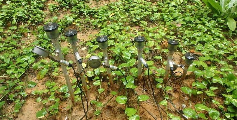
MATEC Web of Conferences 337, 03021 (2021)                                                         https://doi.org/10.1051/matecconf/202133703021
PanAm-UNSAT 2021

                                            Fig. 2. Selection of rainfall condition from IDF curve [14].

           As natural sand needs to be imported in Singapore,                gentle angle to provide sufficient sunlight into the
       alternative material is needed to replace the natural sand            carpark. The slope had a height of 3.5 m and a slope angle
       in CBS due to its cost and limitation of resources.                   of 25°. Prior to the construction of CBS, numerical
       Recycled concrete aggregate (RCA) from construction                   analyses were conducted to determine the optimum
       and demolition waste, but mainly from crushed concrete                thickness of the CBS.
       of demolition waste is encouraged to be used in new                       The CBS was designed with a thickness of 20 cm for
       construction work in Singapore. Rahardjo et al. (2020)                the ASM, 30 cm for the fine-grained layer and 20 cm for
       [12] indicated that recycled construction material such as            the coarse-grained layer. Two-dimensional seepage
       RCA could have similar performance as the natural sand                analyses were carried out using the finite element
       in the capillary barrier.                                             software SEEP/W ([13]). During construction of the
           In this study, the surface material of CBS was                    basement carpark, there is always one-meter over-
       vegetated to provide greenery into the surrounding                    excavation. In this case, there will be one-meter thick
       environment and for aesthetic purposes. An approved soil              layer of backfill soil underlying CBS. The intensity-
       mixture (ASM) which is a mixture of organic soil and                  duration-frequency (IDF) curve was used for the
       sandy material was used as the additional layer placed on             determination of flux boundary condition. A rainfall
       top of the CBS for plant growth. In general, the CBS was              intensity of 18 mm/hour was determined from the curve
       constructed using three layers of soil with ASM as                    corresponding to ten hours duration and return period of
       material as the top most layer, followed by fine RCA as               50 years, as illustrated in Figure 2.
       fine-grained material and coarse RCA as coarse-grained                    The numerical model and the boundary conditions
       material.                                                             were presented in Figure 3. Samples were taken from the
           The objective of this paper is to describe the                    site for SWCC measurements and the measured SWCCs
       construction and performance of the CBS as a sustainable              of these soil samples were illustrated in Figure 4a. The
       slope cover which was constructed surrounding basement                statistical method as illustrated in Zhai et al. (2017 [15],
       carpark of HDB flats in Matilda, Singapore. The scope of              2018 [16]) equation was used for the estimation of the
       works includes the installation of comprehensive                      permeability functions shown in Figure 4b. Groundwater
       instruments to provide real-time monitoring of rainwater              table was located at 1.5 m below the ground surface near
       infiltration into the slope and numerical analyses to assess          the toe. Eight measurement points (as illustrated in Figure
       the performance of CBS as a sustainable slope protection              3) were selected to assess the performance of CBS in
       against rainfall-induced slope failure.                               minimizing the rainwater into the soil below the CBS.
                                                                                 Zhai et al. (2017) [17] and Tami et al. (2004) [18]
                                                                             suggested that the hysteretic behavior of hydraulic
       2 Design of capillary barrier system                                  properties of soil needs to be accounted for in the
       The slope consists of residual soil from Old Alluvium in              numerical modeling of unsaturated flow system to
       Matilda. It was located surrounding basement carpark of               provide realistic results. Therefore, both wetting SWCC
       residential buildings in Singapore. In order to minimize              and wetting permeability functions (as illustrated in
       the usage of electricity, the slope was designed with a               Figure 4) were used for the seepage analysis. The results
                                                                             from the numerical analyses are illustrated in Figure 5.

       *
           Corresponding author: alfrendo.satyanaga@nu.edu.kz

                                                                         2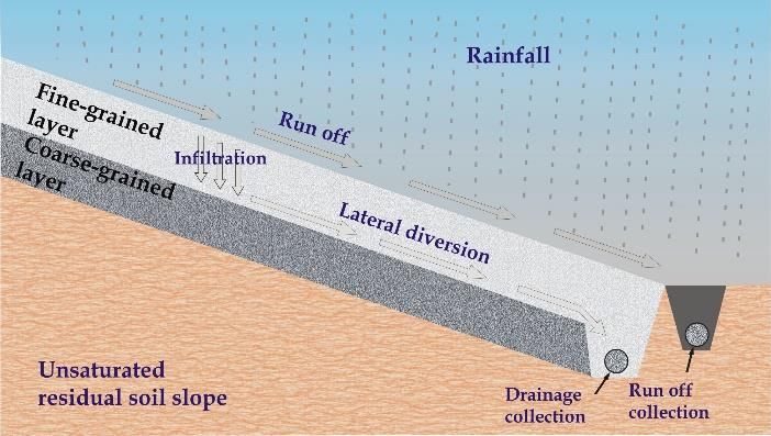
MATEC Web of Conferences 337, 03021 (2021)                                                                                                               https://doi.org/10.1051/matecconf/202133703021
PanAm-UNSAT 2021

                                                                                       Fig. 3. Numerical model of capillary barrier system.

              As illustrated in Figure 5, during the rainfall period                                                            3 Construction                 of    capillary        barrier
       (first 10 hours), a significant decrease in suction, which                                                               system
       represents the occurrence of infiltration, is only observed
       in the ASM and fine RCA layers while an insignificant                                                                    The grain-size distribution (GSD) of materials used in
       decrease is observed in the coarse RCA layers and no                                                                     CBS must be checked against the requirement (i.e., upper
       change in suction is observed in the backfill soil layer. The                                                            bound and lower bound of GSD) in the specification
       results from seepage analysis indicate that the CBS                                                                      (HDB, 2016) [19] as presented in Figure 6 before they
       system has good performance in storing rainwater for                                                                     were placed on site. The selection of ASM must follow
       plant growth and acting as a barrier to rainwater                                                                        the specification as specified in Table 1 to ensure the
       infiltration into the underlying soil layer.                                                                             livability of the plant.

                                      0.6
                                                 (a)                                                  ASM
                                                                                                      Fine RCA
                                      0.5                                                             Coarse RCA
                                                                                                      Backfill soil
       Volumetric water content, Tw

                                                                                                      Existing soil
                                      0.4

                                      0.3

                                      0.2

                                      0.1

                                      0.0
                                         10-2          10-1   100    101      102     103      104          105       106
                                                                    Matric suction, \ (kPa)
                                                                                                                                Fig. 5. Computed pore-water pressures at four points near crest
                                                                                                                                of slope with respect to time.
                                      10-2

                                      10-3                                            ASM
                                                 (b)                                  Fine RCA                                                 Table 1. Specifications for ASM.
                                      10-4                                            Coarse RCA
                                                                                      Backfill soil
                                      10-5                                                                                           S/No.    Parameters            Required Range/Value
         Hydraulic conductivity, kw

                                                                                      Existing soil
                                      10-6                                                                                             1          pH                      5.5 to 7.8
                                      10-7                                                                                             2       Electrical       Not exceeding 1500 micron/cm
                                      10-8
                                                                                                                                             Conductivity               (1500 mS/cm)
                                                                                                                                       3     Components
                                      10-9
                                                                                                                                       i)        Sand            Particle size: between 0.05 to
                                      10-10
                                                                                                                                                                2mm. Proportion: from 20% to
                                      10-11                                                                                                                                   75%.
                                      10-12                                                                                           ii)         Silt          Particle size: between 0.002 to
                                      10-13                                                                                                                      0.05mm. Proportion: from 5%
                                      10-14                                                                                                                                  to 60%.
                                          10-2         10-1   100    101      102     103      104          105       106             iii)       Clay                Particle size: less than
                                                                    Matric suction, \ (kPa)                                                                     0.002mm. Proportion: from 5%
                                                                                                                                                                             to 30%.
       Fig. 4. Soil properties: (a) Soil-water characteristic curve
       (SWCC)s and (b) permeability functions of materials used in the
       numerical analyses of CBS slope.

       *
                          Corresponding author: alfrendo.satyanaga@nu.edu.kz

                                                                                                                            3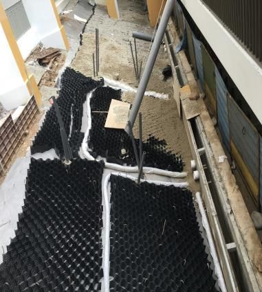
MATEC Web of Conferences 337, 03021 (2021) https://doi.org/10.1051/matecconf/202133703021
PanAm-UNSAT 2021
illustrated in Figure 9. The readings of instruments on site
were automatically collected by datalogger and stored in
a server.
On the other hand, the numerical models for the
seepage analyses were created using two commercial
software Seep/W and SVFlux (version GE) in order to
assess the response of field instruments to the rainfall. The
collected rainfall data (from 1-Jan 2017 to 30-Jun 2017)
from the weather station were used as the flux boundary
condition for the seepage analyses. To avoid cumulative
numerical error from the long-term iteration, a short
simulation period such as one week was adopted for the
seepage analysis. The half-year monitoring period was
divided into twenty-six weeks and a total of 26 models
Fig. 6. Grain-size distribution of Fine and Coarse RCAs. were created. The readings from the tensiometers
collected at the beginning of each week were assigned to
the model and set as the initial condition for the seepage
The construction of the CBS was started by trimming analysis. The final numerical results from the seepage
the slope into the designated slope angle of 25o. Then, it analyses using both Seep/W and SVFlux (version GE) for
was followed by the installation of the surface drainage. 26 weeks are illustrated in Figures 10 to 15. As the
The subsoils drainage pipe consisted of a PVC pipe reference, the rainfall data from 1-Jan 2017 to 30-Jun
perforated in the upper-half diameter, wrapped by the 2017 are also plotted in Figures 10 to 15.
geotextile, placed at the toe of CBS for each layer of soil
behind the surface drainage. Pipe guides were installed
afterward to indicate the location and prepare the hole for
Tube for placing recycled
tensiometers that would be installed after the entire CBS (a) concrete aggregate into GBS
was built. The ASM soil, fine RCA and coarse RCA were Coarse
placed within the geocell with a thickness of 20 cm, 30 recycled
cm and 20 cm, respectively, parallel to the slope surface. concrete
Perforated pipe
aggregate
The geocell was similar to the one used by Rahardjo et al. wrapped with
(2016) and it was secured to the residual soil by steel J- geofabric
Connection for
pins of 40 cm long, penetrating to 20 cm depth into the perforated pipe
ground. Manual compaction was carried out on the fine PVC tube for to open drain
tensiometer
and coarse RCA to achieve the desired density.
During installation of the CBS (including three layers
J-pin Geocell for
such as coarse RCA, fine RCA, and ASM soil), a layer of holding
geotextile was laid on top of the coarse RCA as a separator coarse
between the coarse and fine RCA. A second layer of Geodrain recycled
concrete
geocells was then laid above the geotextile and secured by aggregate
steel J-pins of 80 cm long, penetrating to a depth of 20 cm
into the ground. Fine RCA was then used to fill up the
geocells to form the fine-grained layer. Another layer of (b)
geotextile was laid on top of the fine RCA as a separator
between the fine RCA and ASM. The ASM was placed
on top of the geotextile. Finally, vegetations were planted
in the ASM layer. The comparisons between the measured
grain size distribution (GSD) data and the specified range
(i.e., upper bound and lower bound) in the specification
from HDB (2016) are illustrated in Figure 6. The
construction of CBS is presented in Figure 7a while the
completed CBS slope is illustrated in Figure 7b.
4 Field monitoring and numerical
simulation
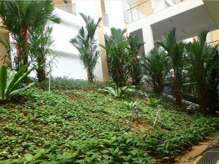
In order to assess the performance of CBS in minimizing
rainwater infiltration into the slope, a total of 12 jet-filled
tensiometers [20] were installed in the different layers of
soil (as illustrated in Figure 8). In order to check the Fig. 7. (a) During and (b) after construction of CBS slope at
reading from the pressure transducer, an additional Matilda.
bourdon gauge was attached to each tensiometer as
4
MATEC Web of Conferences 337, 03021 (2021) https://doi.org/10.1051/matecconf/202133703021
PanAm-UNSAT 2021
Geotextile
Perforated pipe
Fig. 8. Schematic diagram of capillary barrier system at Matilda.
Fig. 9. Tensiometer installed on site.
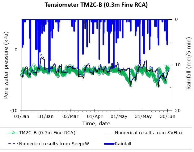
It is observed that the suction in the ASM decreased seepage analyses (either using Seep/W or SVFlux
much faster than that in the fine RCA during rainfall. The (version GE)) agree with the field measurement data.
suction in the coarse RCA remained constant during the Good agreements between the numerical results and the
rainfall. It is also observed that ASM could remain in a field measurements demonstrate that the performance of
relative low suction state during the dry period (such as CBS can be assessed using the numerical method. Both
Feb 2017) which can provide sufficient water for the plant field measurement data and numerical results show that
growth. During the dry period, such as Feb-2017, there the suction in the coarse RCA layer remained constant
was limited rainfall recorded, the suction in ASM did not (with low fluctuation), indicating that there was no
increase drastically, which means that the ASM can store rainwater infiltrating into the underlying soil. Both
the rainwater as the water supply for plant growth. The measurement data and simulation results showed that the
stored water could not infiltrate into the underlying soil low suction value was observed in the ASM layer during
due to the barrier effect provided by fine and coarse RCA dry season (no rainfall period), indicating the presence of
layers. water was within the ASM layer. On the other word, the
As illustrated in Figures 10-15, the numerical results rainwater infiltrated into ASM layer during wet season
from the commercial software such as Seep/W and could be stored in the ASM layer during dry season. The
SVFlux (version GE) agree with each other. In addition, stored rainwater can be used by vegetation planted on the
Figures 10 to 15 also indicate that the results from the surface of CBS.
5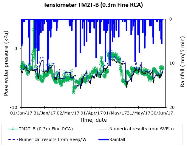
MATEC Web of Conferences 337, 03021 (2021)                                                         https://doi.org/10.1051/matecconf/202133703021
PanAm-UNSAT 2021

                 (a)                                                         (b)

                                  Fig. 10. Comparison results for Tensiometer 1 in ASM at: (a) crest and (b) toe.

                (a)                                                          (b)

                                Fig. 11. Comparison results for Tensiometer 2 in fine RCA at: (a) crest and (b) toe.

               (a)                                                       (b)

                                Fig. 12. Comparison results for Tensiometer 3 in fine RCA at: (a) crest and (b) toe.

       *
           Corresponding author: alfrendo.satyanaga@nu.edu.kz

                                                                         6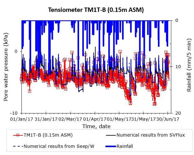
MATEC Web of Conferences 337, 03021 (2021)                                                       https://doi.org/10.1051/matecconf/202133703021
PanAm-UNSAT 2021

           (a)                                                            (b)

                           Fig. 13. Comparison results for Tensiometer 4 in coarse RCA at: (a) crest and (b) toe.

            (a)                                                             (b)

                          Fig. 14. Comparison results for Tensiometer 5 in backfilled soil at: (a) crest and (b) toe.

              (a)                                                            (b)

                          Fig. 15. Comparison results for Tensiometer 6 in backfilled soil at: (a) crest and (b) toe.

                                                                      7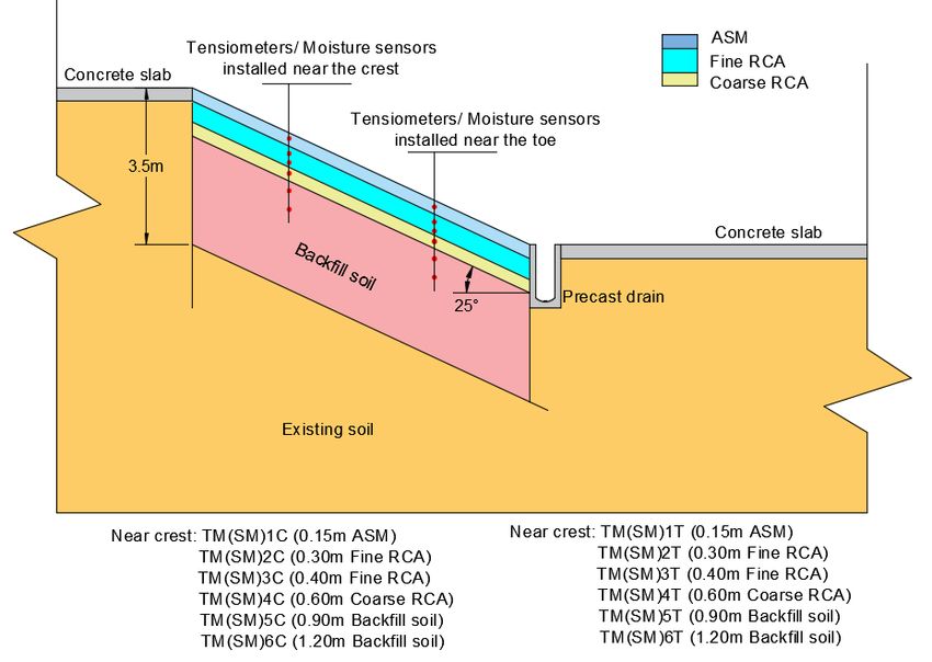
MATEC Web of Conferences 337, 03021 (2021)                                                       https://doi.org/10.1051/matecconf/202133703021
PanAm-UNSAT 2021

       5 Conclusions and recommendations                                   9.    H. Rahardjo, V.A. Santoso, E.C. Leong, Y.S. Ng,
                                                                                 C.P.H. Tam, A. Satyanaga. (2013). Use of recycled
       Capillary Barrier System (CBS) is a sustainable slope                     crushed concrete and secudrain in capillary barriers
       protection which consists of ASM, Fine RCA and Coarse                     for slope stabilization. Canadian Geotechnical J. 50:
       RCA. A CBS was designed and constructed on the slopes                     1-12. doi: 10.1139/cgj-2012-0035
       surrounding a basement carpark in a public housing                  10.   D.G. Fredlund & H. Rahardjo. (1993). Soil
       development at Matilda, Singapore. Both results from                      mechanics for unsaturated soil. Wiley, New York.
       field instrumentation and numerical analyses indicate that
       the constructed CBS performed well under the studied                11.   D.G. Fredlund, H. Rahardjo & M.D. Fredlund.
       rainfall conditions.                                                      (2012). Unsaturated soil mechanics in engineering
                                                                                 practice. Wiley, New York
                                                                           12.   H. Rahardjo, Y. Kim, N. Gofar, A. Satyanaga.
       Acknowledgements                                                          (2020). Analyses and design of steep slope with
                                                                                 GeoBarrier System under heavy rainfall. Geotextiles
       The authors gratefully acknowledge the support from                       and     Geomembranes.        48:2,    157-169. doi:
       Housing and development Board, Singapore and staffs in                    10.1016/j.geotexmem.2019.11.010
       School of Civil and Environmental Engineering,
       Nazarbayev University during the data collections.                  13.   H. Rahardjo, A. Satyanaga, E.C. Leong, Y.S. Ng,
                                                                                 M.D. Foo, C.L. Wang. (2007). Slope failures in
                                                                                 Singapore due to rainfall. Proc. 10th ANZ Conf. on
       References                                                                Geomechanics “Common Ground”. Brisbane,
                                                                                 Australia, 21-24 October, 2, 704 - 709.
       1.    A. Satyanaga, H. Rahardjo, C.J. Hua. (2019).                  14.   H. Rahardjo, A. Satyanaga, E.C. Leong. (2016).
             Numerical simulation of capillary barrier system                    Effects of rainfall characteristics on the stability of
             under rainfall infiltration. ISSMGE Int. J. Geo. Case               tropical residual soil slope. Proc. E-UNSAT 2016.
             Histories. 5:1, 43-54. doi: 10.4417/IJGCH-05-01-04                  15004. 1-6. doi: 10.1051/e3sconf/20160915004
       2.    H. Rahardjo, A. Satyanaga, F.R. Harnas, E.C. Leong.           15.   Q. Zhai, H. Rahardjo, A. Satyanaga, Priono. (2017).
             (2016). Use of dual capillary barrier as cover system               Effect of bimodal soil-water characteristic curve on
             for a sanitary landfill in Singapore. Indian Geo. J.                the estimation of permeability function. Eng.
             46:3, 228-238. doi: 10.1007/s40098-015-0173-3                       Geology.         230,       142-151.               doi:
       3.    H. Rahardjo, A. Satyanaga, F. R. Harnas, J-.Y. Wang,                10.1016/j.enggeo.2017.09.025
             E.C. Leong. (2013). Capillary barrier system for              16.   Q. Zhai, H. Rahardjo, A. Satyanaga. (2018). A pore-
             landfill capping. Proc. Coupled Phenomena in Env.                   size distribution function based method for
             Geo. (CPEG), TC215 Symposium, 1 – 3 July 2013,                      estimation of hydraulic properties of sandy soils.
             Torino, Italy.                                                      Eng.       Geology.       246,      288-292.       doi:
       4.    C.E. Morris & J.C. Stormont. (1998). Evaluation of                  10.1016/j.enggeo.2018.09.031
             numerical simulations of capillary barrier field tests.       17.   Q. Zhai, H. Rahardjo, A. Satyanaga. (2017).
             G. & G. Eng. 16, 201–213.                                           Uncertainty in the estimation of hysteresis of soil-
       5.    H. Rahardjo, A. Satyanaga, N. Gofar, E.C. Leong,                    water characteristic curve. Env. Geo. doi:
             J.H.L. Kew, C.L. Wang, J.L.H. Wong. (2019).                         10.1680/jenge.17.00008
             Geobarrier system for protection against rainfall-            18.   D. Tami, H. Rahardjo, E.C. Leong, D.G. Fredlund.
             induced slope failure. ISSMGE Int. J. Geo. Case                     (2004). Design and laboratory verification of a
             Histories. 5:1, 26-42. doi: 10.4417/IJGCH-05-01-03                  physical model of sloping capillary barrier. Canadian
       6.    H. Rahardjo, N. Gofar, F. Harnas, A. Satyanaga.                     Geotechnical J. 41, 814- 830. doi: 10.1139/t04-036
             (2018). Effect of geobags on water flow through               19.   Housing & Development Board (HDB). (2016).
             capillary barrier system. Geo. Eng. J. SEAGS &                      Construction of geobarrier system. Technical
             AGSSEA. 49:4, 1-6.                                                  specification.
       7.    H. Rahardjo, A. Satyanaga, E.C. Leong. (2012).                20.   H. Rahardjo, A. Satyanaga, E.C. Leong, J.-Y. Wang.
             Unsaturated soil mechanics for slope stabilization.                 (2014). Comprehensive instrumentation for real time
             Southeast Asian Geo. J. 43:1, 48-58.                                monitoring of flux boundary conditions in slope.
       8.    H. Rahardjo, V.A. Santoso, E.C. Leong, Y.S. Ng, C.J.                Procedia Earth and Planetary Science. 9, 23-43. doi:
             Hua. (2012). Performance of an instrumented slope                   10.1016/j.proeps.2014.06.015
             covered by a capillary barrier system. ASCE J. Geo.
             and Geoenv. Eng. 138:4, 481 – 490. doi:
             10.1061/(ASCE)GT.1943-5606.0000600

       *
           Corresponding author: alfrendo.satyanaga@nu.edu.kz

                                                                       8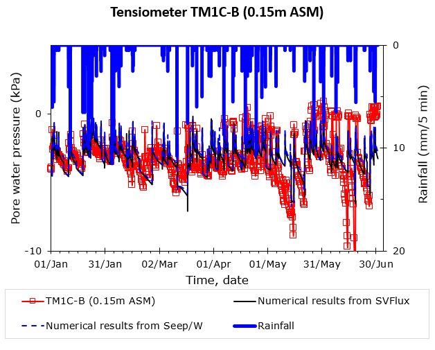
You can also read