Experimental Study and Theoretical Verification of Explosion-Proof Performance of Insulated Glass
←
→
Page content transcription
If your browser does not render page correctly, please read the page content below
Hindawi
Shock and Vibration
Volume 2020, Article ID 4257191, 6 pages
https://doi.org/10.1155/2020/4257191

Research Article
Experimental Study and Theoretical Verification of
Explosion-Proof Performance of Insulated Glass

 Jinju Zhang ,1 Xinjian Wang,1 Liqiong Wang,2 and Pengchong Su3
 1
 School of Public Security and Traffic Management, People’s Public Security University of China, Beijing 100038, China
 2
 State Key Laboratory of Explosion Science and Technology, Beijing Institute of Technology, Beijing 100081, China
 3
 College of Police Information Engineering and Network Security, People’s Public Security University of China,
 Beijing 100038, China

 Correspondence should be addressed to Jinju Zhang; 68430332@163.com

 Received 6 December 2019; Revised 14 March 2020; Accepted 27 April 2020; Published 18 May 2020

 Academic Editor: Enrico Zappino

 Copyright © 2020 Jinju Zhang et al. This is an open access article distributed under the Creative Commons Attribution License,
 which permits unrestricted use, distribution, and reproduction in any medium, provided the original work is properly cited.

 Building glass fragment in a blast-related environment is the main cause of casualties. In order to analyze the explosion-proof
 performance of insulated glass quantitatively in conventional buildings, the explosion experiment under different shock wave
 loads was carried out on the insulated glass, the pressure sensor was used to collect the overpressure value of the explosion shock
 wave, and the high-speed camera was used to record the breaking process of glass. The broken state of the insulated glass and the
 critical overpressure value of the broken state under different working conditions were obtained. And the theoretical calculation
 method based on the equivalent static load was used to verify the critical overpressure value of the insulated glass. The research
 showed that the fragments scattered toward the center of the explosion source when the layer of the insulated glass face to the
 explosion wave front was broken, and the fragments mainly scattered in the direction of the shock wave propagation when it was
 completely broken. The theoretical calculation method based on the equivalent static load could be used to evaluate the explosion-
 proof performance of the insulated glass.

1. Introduction earthquake disaster and by combining with the damage level
 of the building. The impact of building glass breakage on
The statistics of previous explosion events show that more personnel injury was considered in this model. Besides,
than 70% of casualties are caused by splashed glass fragments several numerical simulations with various models have
in the area affected by the explosion [1–3]. Therefore, it is of been conducted to investigate the behaviour of laminated
practical significance to carry out research on the fracture glass under blast loading, including parametric analyses
characteristics of building glass and its explosion-proof [7–10]. Larcher et al. [11] made a review on the abilities of
performance under blast loading. Young et al. [4] established numerical simulations to assess blast-loaded laminated glass
a scattering model of glass fragments by conducting bio- and presented the first idea of standardization in this field.
realistic experiments and developed a glass fragment pen- Meanwhile, many researchers combine experimental and
etration program to analyze the damage caused by the simulation methods to study the performance of glass under
scattering of glass fragments quantitatively. Stewart and blast loading. For instance, Zhang et al. [12, 13] established
Netherton [5] estimated the probability of glass safety the pressure-impulse (P-I) diagrams for PVB laminated glass
performance under impact loading by using a single-degree- to provide correlations between dynamic responses of
of-freedom simplified model. Oswald and Baker [6] estab- laminated glass and blast loadings by numerical simulation
lished a vulnerability assessment model for the occupants in and analyzed the glass fragment velocity and mass of single-
the building by using the data of human injury in the layer tempered glass under explosion load by field experi-
Oklahoma explosion and the data obtained from the ment. Accordingly, in order to reduce the threat from
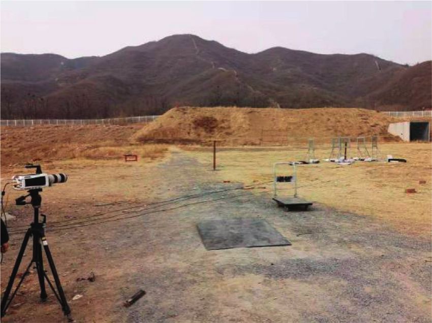
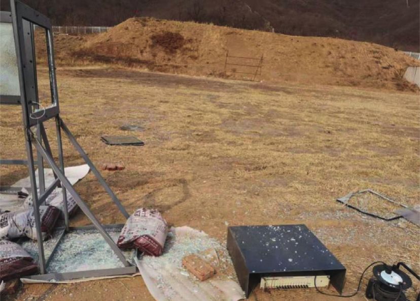
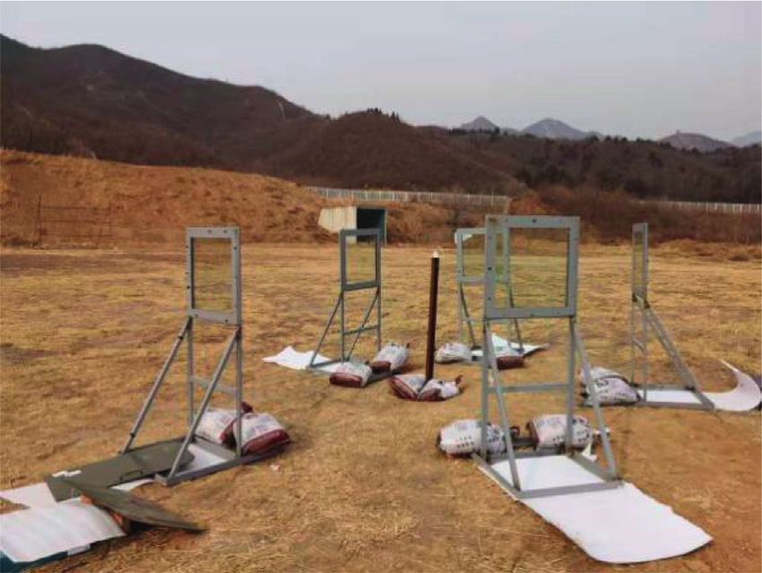
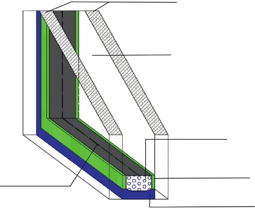
2 Shock and Vibration

shattered glass, mitigation and retrofit methods have also Tempered glass
been explored in the several decades. Norville and Conrath
[14] proved that the insulated glass composed of two
laminated glass had better explosion-proof performance. Li,
Zhang and Chen et al. [15–18] proposed the explosion-proof Air
design method of glass curtain wall by studying the dynamic
response of glass curtain wall under the action of explosion
load. Le [19] compared the explosion test of domestic ex-
plosion-proof glass with ordinary glass, which showed that
increasing the thickness of the glass panel and the number of
 Desiccant
layers of the substrate could improve the ability of the
combined glass to resist the explosion shock wave effectively.
Zhang and Bedon [20] discussed the current methods and Primary sealant
trends for mitigating blast-related hazards on glass windows, Spacer bar
including interlayer anchors, catching systems, and sliding (aluminum)
 Secondary sealant
supporting systems.
 It can be seen that the research on the glass under blast Figure 1: The structural drawing of the insulated glass.
loading mainly focuses on the laminated glass with good
explosion-proof performance and the design of explosion- has the same height as the explosion source; two pressure
proof glass structure, but the explosion-proof performance sensor probes are installed on different glass support frames,
of the insulated glass used as the conventional glass for civil and a high-speed camera is placed at a certain distance from
buildings has not been researched. Therefore, the conven- the explosion source to take pictures of the breaking process
tional insulated tempered glass in civil buildings was selected of one piece of glass.
as the research object in this paper. The explosion-proof
performance of the insulated glass was analyzed quantita-
tively by the experimental research on the fracture char- 2.2. Experimental Results and Analysis
acteristics and the critical overpressure threshold of the
 2.2.1. Broken State of Insulated Glass and Its Flying
insulated glass under different blast loadings. And the ex-
 Characteristics. A total of three explosion tests are con-
perimental results were verified by using the theoretical
 ducted according to the above experimental scheme. The
analysis method, which could provide a reliable theoretical
 specific test conditions and the corresponding broken states
evaluation method for the explosion-proof performance of
 of glass are shown in Table 1. It can be seen from Table 1 that
insulated glass and then provide theoretical support for the
 as the distance from the explosion source decreases, the layer
explosion-proof design of architectural glass.
 of the insulated glass face to the explosion wave front breaks
 first and the layer back to the explosion wave front remains
2. Test of Explosion-Proof Performance of intact. The glass fragments scatter toward the center of the
 Insulated Glass explosion source, as shown in Figure 3. The reason is that
 when the blast wave load acting on the layer of the insulated
2.1. Experimental Design. This experiment is designed to
 glass face to the explosion wave reaches the tensile strength
analyze the explosion-proof performance of the insulated
 of the glass, the layer will break. When the shock wave passes
glass, especially to explore the critical overpressure value of
 through the crack from the first layer and reaches the second
the broken glass. The size of the insulated glass selected in
 layer of the insulated glass, the reflection wave will be
this experiment is 600 mm × 600 mm, and the structure is
 generated, which will push the fragments on the first layer to
6 mm tempered +12 mm air +6 mm tempered. The struc-
 fly to the center of the explosion source. When the distance
tural drawing of the insulated glass is shown in Figure 1. A
 from the explosion source is reduced to 0.52 m, both of the
total of 20 specimens are prepared.
 front and back layers of the insulated glass are broken and
 In the experiment, PCB pressure sensors are used to
 the glass fragments fly outward along the direction of shock
measure the value of shock wave overpressure, and a high-
 wave propagation, as shown in Figure 4.
speed camera is used to record the breaking process of glass
under different explosion loads. The explosive source used in
the experiment is cylindrical TNT charge, each of which has 2.2.2. Explosion Shock Wave Overpressure Value. A total of
a mass of 0.1 kg, and it is detonated by a detonator. First, the six effective shock wave overpressure values are recorded in
insulated glass is fixed on the glass support frame, and each this experiment, as shown in Table 2. The following shock
piece of glass is marked, then the glass is placed around the wave overpressure values are fitted, and the calculation
explosion source with different distances and the distance formula of the actual overpressure peak value at the glass
from the explosion source for the next experiment will be center under different working conditions in this experiment
adjusted according to the experimental results until the is obtained, as shown in formula (1) where Δpg is the
critical explosion distance for the completely broken state of overpressure peak value on glass, MPa; W is the explosion
the insulated glass is found. The overall layout of the ex- charge (TNT equivalent), kg; and r is the distance from the
perimental site is shown in Figure 2; the center of the glass explosion source, m.
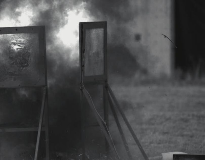
Shock and Vibration 3

 TNT
 Pressure
 Pressure sensors charge High-speed
 sensors
 camera

 (a) (b)

 Figure 2: The overall layout of the test site.

 Table 1: Test conditions and the broken state of glass.
 Explosion charge Glass Distance
No. State of glass
 (kg) number (m)
 G-1 2.5 Intact
 G-2 2.3 Intact
1 0.1 G-3 2 Intact
 G-4 1.5 Intact
 G-5 1 Intact
 G-6 0.9 Intact
 G-7 0.8 Intact
 The layer face to the explosion wave front is broken and scattered, and the back is
 G-8 0.7
2 0.1 intact
 The layer face to the explosion wave front is broken and scattered, and the back is
 G-9 0.6
 intact
 G-10 0.5 Both the layer of glass are broken and scattered
 The layer face to the explosion wave front is broken and scattered, and the back is
 G-11 0.57
 intact
 The layer face to the explosion wave front is broken and scattered, and the back is
 G-12 0.55
3 0.1 intact
 The layer face to the explosion wave front is broken and scattered, and the back is
 G-13 0.54
 intact
 G-14 0.52 Both the layers of glass are broken and scattered
 √3 �� √3 �� 2 √3 �� 3 face to explosion wave front of the insulated glass used in this
 W W W
 Δpg � −0.975 + 6.627 − 1.047 , (1) experiment is between 1.461 MPa∼1.962 MPa, while the
 r r r
 critical overpressure value of the complete fracture is be-
 The fitting correlation coefficient is 0.99299. By this tween 3.393 MPa∼3.665 MPa.
fitting formula, the shock wave overpressure value at the The critical overpressure threshold of glass fracture is
center of the insulated glass under different working con- related to the structure, thickness, area, aspect ratio, and
ditions can be calculated, as shown in Table 3. boundary conditions of the glass [21]. In order to verify the
 critical overpressure threshold of the insulated glass, the
 equivalent static load method is used to analyze the struc-
3. Theoretical Verification of the Critical tural dynamic response of the insulated glass under the
 Overpressure Threshold of Insulated Glass explosion load, and the elastic working stage of the glass is
 calculated according to the single-degree-of-freedom
It can be seen from Table 1 that, when the TNT equivalent is system.
0.1 kg, the distance from the explosion source is between The equivalent static load of insulated glass can be
0.7 m∼0.8 m for the single-layer face to the explosion wave calculated according to the following formula [22, 23]:
front of the insulated glass breaking and the distance from
the explosion source for complete breaking is between qe � Kd Δpg , (2)
0.52 m∼0.54 m. According to the overpressure value cal-
culated by the fitting formula in Table 3, it can be determined where qe is the equivalent static load, N/mm2, and Kd is the
that the critical overpressure value of the fracture of the layer dynamic coefficient of the structural member.
4 Shock and Vibration

 (a) (b)

 (c) (d)

 Figure 3: The fragment throwing process of G-8 in test 2. (a) t � 0.02 s. (b) t � 0.20 s. (c) t � 0.40 s. (d) t � 1.04 s.

 Table 3: The shock wave overpressure value at the center of the
 glass.
 W (kg) r (m) Δpg (MPa)
 0.1 2 0.118
 0.1 1 0.870
 0.1 0.9 1.116
 0.1 0.8 1.461
 0.1 0.7 1.962
 0.1 0.6 2.727
 0.1 0.57 3.035
 0.1 0.54 3.393
 Figure 4: The test result of G-14 in test 3. 0.1 0.52 3.665
 0.1 0.50 3.968

 Table 2: The test value of shock wave overpressure. where ω is the self-vibrating circle frequency of the
 equivalent single-degree-of-freedom system structural
Explosion charge (kg) Distance (m) Overpressure value (MPa)
 member, 1/s; t0 is the equivalent action time of the dy-
0.1 2.02 0.122 namic load, s; and [μ] is the allowable ductility ratio of the
0.1 0.76 1.421
 structure or component, where the glass is taken as 1.
0.1 0.64 2.240
0.1 0.62 2.422 The equivalent action time of dynamic load t0 on the
0.1 0.60 2.572 insulated glass can be calculated as follows:
0.1 0.57 2.705 2i
 t0 � f , (4)
 Δpg
 When the waveform of the explosive dynamic load is
simplified to a triangle without boost time, the dynamic W2/3
 if � 2i+ � 5 , (5)
coefficient of the structural member is calculated as follows: r
 2 �������
 −1
 2[μ] − 1 where if is the reflected shock wave impulse, Pa S, and it is
 Kd � 2[μ] − 1 + , (3) calculated according to the empirical formula [24]. i+ is the
 ωt0 2[μ] 1 + 4/ωt0
 positive phase impulse of shock wave, Pa S.
Shock and Vibration 5

 The self-vibrating circle frequency of glass can be cal- Table 4: Maximum stress on insulated glass under different
culated according to the self-vibration circle frequency of the working conditions.
flexure type of two-way wall (board): State of glass (the
 ��� W r Δpg σ1 σ2
 Ω Dg results of
 (kg) (m) (MPa) (N·mm−2) (N·mm−2)
 ω� 2 , (6) experiment)
 lx ch
 1.0 0.870 60.840 55.860 Intact
where Ω is the frequency coefficient, which is 19.74 according 0.9 1.116 66.798 61.405 Intact
to the installation method of insulated glass in this experiment. 0.8 1.461 74.007 68.141 Intact
 The layer face to the
lx is the span of the wall (board), m. And it was taken as 0.6 m
 explosion wave
in this experiment. c is the unit weight of the wall (board), 0.7 1.962 82.893 76.483
 front is broken, and
kg/m3. The unit weight of tempered glass is 2500 kg/m3. h is the the back is intact
thickness of the wall (board), m.g is the gravity acceleration, m/ The layer face to the
s2. D is the bending stiffness of the wall (board), N mm. explosion wave
 0.6 2.727 94.204 87.054
 The bending stiffness of a single glass is calculated front is broken, and
according to the following formula [25]: the back is intact
 0.1 The layer face to the
 Eh3
 D� , (7) 0.57 3.035 98.395 90.789
 explosion wave
 12(1 − v2 ) front is broken, and
 the back is intact
where E is the modulus of elasticity, N/mm2. The modulus of The layer face to the
elasticity of the tempered glass is 7.2 × 10⁴ N/mm2. v is explosion wave
Poisson’s ratio of glass, and Poisson’s ratio of tempered glass 0.54 3.393 102.961 95.020
 front is broken, and
is 0.20. the back is intact
 The equivalent thickness method [26] should be used Both the layers of
 0.52 3.665 106.238 98.110
when calculating the bending stiffness of insulated glass, and glass are broken
the equivalent thickness of insulated glass is derived from the Both the layers of
 0.50 3.968 109.719 101.340
assumption of equal deflection of the upper and lower layers glass are broken
of insulated glass [25, 27], that is,
 1/3 where q1 is the equivalent static load on the layer of the glass face
 heq � 0.95 h31 + h32 . (8)
 to the explosion wave front, while q2 is on the layer of the glass
 Here, the reduction factor of 0.95 is taken for consid- back to the explosion wave front, N/mm2. θ1 and θ2 are the
ering the existence of an air layer in the insulated glass; heq is parameters; m is the bending moment coefficient. When the
the equivalent thickness of the insulated glass, m; and h1 and ratio of the long side to the short side of the glass is 1, m is 0.0442
h2 are the thickness of the upper and lower layers of the according to the table of bending moment coefficient in [25]; η1
insulated glass, respectively. The equivalent thickness of the and η2 are the reduction coefficients, which are determined by
insulated glass is 7.182 mm, calculated from formula (8). the table of reduction coefficient in [25], respectively.
 The equivalent static load on the insulated glass can be According to the above calculation method, the maxi-
obtained by using formula (2)∼(8), and the equivalent static mum stress on the upper and lower layers of insulated glass
load and the maximum stress distributed to two layers of at different distances from the explosion source under the
glass are calculated, respectively, as follows: explosion of 0.1 kg TNT equivalent explosive is calculated,
 h3 which are compared with the experiment results of glass’s
 q1 � 1.1qe 3 1 3 , broken state. The results are shown in Table 4.
 h1 + h2
 According to the design code (JCJ102-2003), the design
 q1 l4x tensile strength of tempered glass is 84 N/mm2 [25]. And the
 θ1 � , failure criterion of glass is that when the maximum dynamic
 Eh4eq stress on glass exceeds the design value of strength, the glass will
 break. However, the strength of the glass material itself is highly
 6mq1 l2x discrete [28], so the glass breakage often occurs within a certain
 σ1 � η,
 h2eq 1 range of the design value of strength. It can be seen from
 (9) Table 4 that the experiment results of glass’s broken state are in
 h3 good agreement with the theoretical calculation results.
 q2 � qe 3 2 3 ,
 h1 + h2
 4. Conclusion
 q l4
 θ2 � 2 4x , When the single layer of the insulated glass face to the
 Eheq
 explosion wave front is broken, the fragments will fly to the
 6mq2 l2x center of the explosion source, and when it is completely
 σ2 � η, broken, the fragments will mainly fly in the direction of
 h2eq 2
 shock wave propagation.
6 Shock and Vibration

 The critical overpressure value for the broken state of the [8] J. Wei and L. R. Dharani, “Response of laminated architectural
layer face to the explosion wave front of the insulated glass is glazing subjected to blast loading,” International Journal of
between 1.461 MPa∼1.962 MPa, while the critical over- Impact Engineering, vol. 32, no. 12, pp. 2032–2047, 2006.
pressure value for the completely broken state is between [9] M. Timmel, S. Kolling, P. Osterrieder, and P. A. Du Bois, “A
3.393 MPa∼3.665 MPa. finite element model for impact simulation with laminated
 glass,” International Journal of Impact Engineering, vol. 34,
 The theoretical calculation method based on the
 no. 8, pp. 1465–1478, 2007.
equivalent static load is used to verify the critical over- [10] X. N. Gao and S. P. Wang, “Deflection of architectural
pressure value of the insulated glass. The calculation results laminated glasses under static and explosive loads,” Journal of
are in good agreement with the experiment results, which the Chinese Ceramic Society, vol. 10, pp. 1477–1482, 2008.
shows that the theoretical calculation method adopted in this [11] M. Larcher, M. Arrigoni, C. Bedon et al., “Design of blast-
paper can be used to evaluate the explosion-proof perfor- loaded glazing windows and facades: a review of essential
mance of the insulated glass. As a part of an ongoing re- requirements towards standardization,” Advances in Civil
search activity, the experimental results will be validated by Engineering, vol. 2016, Article ID 2604232, 14 pages, 2016.
numerical simulation, to further verify the feasibility of the [12] X. Zhang, H. Hao, and G. Ma, “Parametric study of laminated
theoretical calculation method. glass window response to blast loads,” Engineering Structures,
 vol. 56, pp. 1707–1717, 2013.
 [13] X. Zhang, H. Hao, and Z. Wang, “Experimental investigation
Data Availability of monolithic tempered glass fragment characteristics sub-
 jected to blast loads,” Engineering Structures, vol. 75,
All data included in this study are available from the cor- pp. 259–275, 2014.
responding author upon request. [14] H. S. Norville and E. J. Conrath, “Considerations for blast-
 resistant glazing design,” Journal of Architectural Engineering,
Conflicts of Interest vol. 7, no. 3, pp. 80–86, 2001.
 [15] Y. C. Li, Study on the Capability of Resistance to Blast of Glass
The authors declare that there are no conflicts of interest Curtain Wall, Shenyang University of Technology, Shenyang,
regarding the publication of this paper. China, 2014.
 [16] J. Chen, Q. S. Zhang, and X. H. Li, “Blast protecion design of
Acknowledgments glass curtain wall in high-rise building,” Journal of Shandong
 Jianzhu University, vol. 22, no. 5, pp. 387–390, 2007.
This work was supported by the National Key Research and [17] J. Chen and D. S. Wang, “Blast resistance design for curtain
Development Program of China (No. 2018YFC0824005-2) wall of high-rise building,” Journal of Building Structures,
and the Fundamental Research Funds for the Central vol. S1, pp. 224–227, 2009.
Universities (No. 2020JKF311). Special thanks are given to [18] W. D. Lv, H. Huang, and L. Gan, “Anti-blast protective design
professorate senior engineer Qingliang Shao for his helpful of glass curtain wall,” Steel Construction, vol. 26, no. 12,
 pp. 20–24, 2011.
consultation in accomplishing this paper.
 [19] X. H. Le, Explosion Test and Application of Bomb Proof Glass
 System, Shantou Technology Shantou, China, 2007, http://
References www.cnki.com.cn/Article/CJFDTotal-STKI200703020.htm.
 [20] X. Zhang and C. Bedon, “Vulnerability and protection of glass
 [1] T. Bruck, “The economic consequences of the new global ter- windows and facades under blast: experiments, methods and
 rorism,” Economic Bulletin, vol. 39, no. 10, pp. 327–332, 2002. current trends,” International Journal of Structural Glass and
 [2] W. G. Corley, P. F. Mlakar, M. A. Sozen, and C. H. Thornton, Advanced Materials Research, vol. 1, no. 2, pp. 10–23, 2017.
 “The Oklahoma city bombing: summary and recommenda- [21] H. G. Deng, Research On Dynamic Response and W-R Method
 tions for multihazard mitigation,” Journal of Performance of for Blast Resistant Design of Laminated glass, South China
 Constructed Facilities, vol. 12, no. 3, pp. 100–112, 1998. University of Technology, Guangzhou, China, 2016.
 [3] P. F. Mlaker, W. G. Corley, M. A. Sozen, and C. H. Thornton, [22] GB 51182-2016, Code For Design of Architechture and
 “The Oklahoma city bombing: analysis of blast damage to the Structure for the Factory of Explosive and Their Products,
 murrah building,” Journal of Performance of Constructed China Planning Press, Beijing, China, 2016.
 Facilities, vol. 12, no. 3, pp. 113–119, 1998. [23] GB50038-2005, Code For Design of Civil Air Defense Base-
 [4] L. A. Young, D. Stevents, and K. Marchand, “Glass shard FLY- ment, China Planning Press, Beijing, China, 2010.
 Out and penetration model,” in Procedings Of the 11th In- [24] Explosion and its Role (Volume II), pp. 43–47, National De-
 ternational Symposium on Interaction Of the Effects Of Mu- fense Industry Press, Beijing, China, 1979.
 nitions With Structures, Mannheim, Germany, May 2003. [25] JCJ102-2003, Technical Code for Glass Curtain Wall Engi-
 [5] M. G. Stewart and M. D. Netherton, “Security risks and neering, China Building Industry Press, Beijing, China, 2004.
 probabilistic risk assessment of glazing subject to explosive [26] S. H. Pang, Effective Thickness Research of Laminated Glass,
 blast loading,” Reliability Engineering & System Safety, vol. 93, China Building Materials Academy, Beijing, China, 2009.
 no. 4, pp. 627–638, 2008. [27] J. N. Zhao and Q. L. Zhang, “Research of the calculation
 [6] C. J. Oswald and Q. A. Baker, “Vulnerability model for oc- theory of the hollow glass,” Building Structure, vol. 36, no. S1,
 cupants of blast damaged building,” in Proceedings of the 9th pp. 85–87, 2016.
 International Symposium on Interaction of the Effects of [28] G. Q. Li, J. Ge, and S. W. Chen, “Fragmentation performance
 Munitions with Structures, Berlin, Germany, May 1999. of glass plate under blast loading-Part Π: experimental ver-
 [7] L. Figuli, Z. Zvaková, and C. Bedon, “Design and analysis of ification,” China Civil Engineering Journal, vol. 47, no. 3,
 blast loaded windows,” Procedia Engineering, vol. 192, pp. 59–68, 2014.
 pp. 177–182, 2017.
You can also read