Construction of plastic deformation areas in a homogeneous base of strip foundation
←
→
Page content transcription
If your browser does not render page correctly, please read the page content below
E3S Web of Conferences 281, 01026 (2021) https://doi.org/10.1051/e3sconf/202128101026
CATPID-2021 Part 1

 Construction of plastic deformation areas in a
 homogeneous base of strip foundation
 Oksana Bogomolova1* and Andrey Zhidelev2b
 1Volgograd State Technical University, 400005, Volgograd, Russia
 2Vzlet
 Branch of the Moscow Aviation Institute (National Research University) in Akhtubinsk, 416501,
 Akhtubinsk, Russia

 Abstract. The article discusses two approaches to the question of plastic
 deformations constructing areas in a homogeneous baseof a strip foundation:
 a trivial approach based on the use of the Coulomb plasticity condition, and
 the approach proposed by the authors based on the approximate analytical
 solution of the theory of elasticity and the theory of soil plasticity mixed
 problem. It has been established that the "Coulomb" regions, which
 originally generated under the edges of the strip load, close under the
 basement as it increases and form a single crescent-shaped plastic area.
 Plastic areas built on the basis of a mixed solution develop inward and
 outward from the foundation. Their closure under the foundation occurs at
 the beginning of the soil uplift process under the foundation, which is
 accompanied by the appearance of deep heaving zones (Fig. 8; 9). All other
 things being equal, the "Coulomb" regions are much larger in size and
 extend to a greater depth than the regions constructed on the basis of a mixed
 solution of the theory of elasticity and the theory of soil plasticity problem.
 The elastic soil core, enveloped by "Coulomb" plastic areas, has a shape
 close to the shape of a half ellipse or a curved trapezoid, and, alternatively,
 has the shape of an isosceles triangle with concave lateral sides. If we
 construct the regions of plastic deformations at the base of a strip foundation
 using the Coulomb plasticity condition, or apply a solution to a mixed
 problem, then, all other things being equal, the sizes of the “Coulomb”
 regions, the “rate” of their development and sensitivity to changes in the
 value of the lateral pressure coefficient of the soil will always be more than
 in the alternative case. If the value of the ultimate load is taken as its value
 corresponding to the closure of the plastic areas under the foundation, then
 the mixed solution of the theory of elasticity and the theory of plasticity of
 soils problem gives higher (≥500%) the values of the latter. When finding
 the value of the bearing capacity of the strip foundation base, it is
 recommended to apply the solutions of the corresponding problems in the
 elastoplastic (mixed) formulation, since their results, and this has been
 shown in the work, are in satisfactory agreement with the experimental data.

 1 Introduction

 * Corresponding author: boazaritcyn@mail.ru

© The Authors, published by EDP Sciences. This is an open access article distributed under the terms of the Creative Commons
Attribution License 4.0 (http://creativecommons.org/licenses/by/4.0/).
E3S Web of Conferences 281, 01026 (2021) https://doi.org/10.1051/e3sconf/202128101026
CATPID-2021 Part 1
To construct the areas of plastic deformations at the foundation base, most authors have
used the solutions to problems of the linear theory of elasticity together with the Coulomb
plasticity condition [1] until recently, which is usually written using one of the expressions
below:
1 − 2 = ( 1 + 2 + 2 ) ,
or
2
( − )2 + 4 = ( + + 2 )2 2 , (1)
or
{ tg = ,
where: 1 and 2; x; z and xz are the dimensionless (in fractions γh) principal normal
stresses and stress components at the point under consideration; sС(γhtg)-1 defines the
reduced connectivity pressure; С; ; γ and max are the specific adhesion, the angle of internal
friction, the bulk density of the soil and the angle of maximum deflection, respectively; h
determines foundation depth.
We propose a slightly different approach [3] to the problem of constructing "Coulomb"
plastic areas, which consists in the following.
Let us write down the Coulomb strength condition in the form proposed by Cagout [2],
additionally introducing some function of the stress state K, which we will call the safety
factor of stability at the point of the soil massif.
= ( + ) (2)
At K=1 the expression (2) coincides with the Coulomb plasticity condition.
Let us express the stresses n and n through their components z; x; xz and the
inclination angle of the shear pad at the point in question (for the design scheme, see Fig.
1a); and, substituting the obtained expressions into the formula (2), we have
[0,5( − ) 2 +0,5( + )+ 2 + ]
= (3)
0,5( − ) 2 + 2
where: the numerator and denominator of the formula (3) are respectively equal to the holding
one (internal friction and adhesion) Fud and shifting Fcd forces acting along the shear site at
the considered point of the soil mass.
a) b) c)
Fig. 1. Calculation schemes for solving the "Coulomb" (a) and mixed (b, c) tasks
If FudFcd, then the soil strength at the point under consideration is not exhausted and the
soil at this point is in a "pre-limiting" state, if FudFcd, then the soil strength has been
exhausted, and the soil at this point is in a "transcendent" (plastic) state. If a Fud=Fcd, then this
2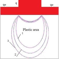
E3S Web of Conferences 281, 01026 (2021) https://doi.org/10.1051/e3sconf/202128101026
CATPID-2021 Part 1
point lies on the border of the elastic and plastic areas. Thus, the line at each point of which
the condition Fud=Fcd (or К=1), is the boundary between elastic and plastic areas. It is this
algorithm of the "traditional" construction of plastic areas that we used in the preparation of
this article.
The second technique we used when writing this article is based on an approximate
analytical solution of the theory of elasticity and the theory of soil plasticity [3-6] mixed
problem, the results of which are presented below.
In the works [3-6] it is shown that the stresses at the points of the plastic area (marked
with a prime) are calculated by the formulas
, = ;
( − )−2
, = ;
+ (4)
, ( + )
{ = .
+
1
where: b tg 2 tg 2[ - (45 / 2)] ; l (1 b ) 2 ; z is the vertical
2
component of the stress at the point under consideration, found from the solution of the
corresponding problem of the theory of elasticity.
The boundaries between elastic and plastic areas are determined on the ratio basis (for the
design scheme, see Fig. 1b, c)
,
2( + )
2 = , (5)
2 − −
( ×(3+ 2 )+ (1−2 )+2 2 )
= (6)
−( + )+2 + 2 ( −3 −2 )−2 2 ( + ( + ))
The expression (5) determines the value of the tangent inclination angle to the plastic area
boundary at the point under consideration. The expression (6) determines the value of the
internal friction angle at the points lying on the plastic area boundary, at any point of which
the inequality < . The line at each point of which the equality = is
fulfilled, is the plastic area boundary.
2 Purpose of the work
The purpose of this work is to assess the development rate (propagation depth increase) of
plastic deformation areas with an increase in the external load intensity, determined by the
traditional ("Coulomb") method, and the method based on the solution of a mixed problem,
as well as to compare their shape, size, and position at appropriate loads.
A comparison of the plastic areas, determined experimentally by other researchers
independently of us, with the plastic areas, the construction of which is carried out on the
basis of the mixed problem analytical solution for the experimental conditions, will be carried
out. It should be noted that the authors with all their efforts failed to find the analytical
expressions similar to those given in [3-6], with the help of which it would be possible to
construct plastic domains for the conditions of the theory of elasticity and the theory of soil
plasticity mixed problem in the scientific literature. Therefore, the results of the experiments
were "calculated" using the computer programs [7-8], developed with the participation of one
of the authors. These programs formalized: to determine the stress state of the soil massif -
the finite element method, and to construct plastic areas - the Coulomb plasticity condition
3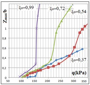
E3S Web of Conferences 281, 01026 (2021) https://doi.org/10.1051/e3sconf/202128101026 CATPID-2021 Part 1 and an approximate analytical solution of the theory of elasticity and the theory of soil plasticity mixed problem [3-6]. 3 Calculation results and their analysis A hypothetical homogeneous soil with the following values of physical and mechanical characteristics was adopted as a foundation model: γ=18kN/m3, φ=21о, с=25kPa, base soil deformation modulus Eо=25МPа, and the lateral pressure coefficient о=0,54. Fig. 2 shows the images of plastic areas (PA) in the base under strip load, determined on the basis of condition [1] (formula (3)) (a), and solving the mixed problem [3-6] (formulas (5;6)) (b, c, d) provided that q1=263kPа, q2=307kPа, q3=352kPа. The load is applied directly to the base surface, and the deepening of the foundation (h=2m) imitated by the side loads. a) b) c) d) Fig. 2. Areas of plastic deformation in the base under strip loading, plotted based on the Coulomb condition (а) and solving a mixed problem [2;3] (b; c; d) for three values of the external influence intensity q1=263kPа, q2=307kPа, q3=352kPа and at γ=18кN/m3, φ=21о, с=25kPа, Eо=25МPа, о=0,54. Fig. 3 shows the images of plastic areas at the moment of their closing under a strip load. The intensity of the external influence corresponding to this moment is often considered as the intensity of the maximum permissible load on the foundation. In the case under consideration, the "Coulomb" regions closed at =207,8kPa, that is, when the value is 21% less q1 (see Fig. 2), and "mixed" at =1070kPa, which is more than 5 times the previous value. a) b) Fig. 3. Plastic areas at the moment of their closure under load: "Coulomb" (a), "Mixed" (b) Analyzing the images shown in Fig. 2, 3, we can note the following significant differences between the "Coulomb" regions and PA, built on a mixed solution basis: 1. “Coulomb” PA, initially originated under the edges of the strip load for all accepted values q, closed and formed a single area. Their closing (see Fig. 2a) happened even before the intensity of the external influence reached the value q=q1=263kPа, which corresponds to 4
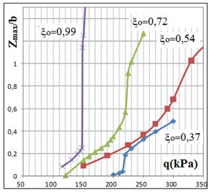
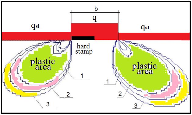
E3S Web of Conferences 281, 01026 (2021) https://doi.org/10.1051/e3sconf/202128101026
CATPID-2021 Part 1

 the first stage of loading. It turned out that the value of the maximum permissible load
 intensity on the base in this case is equal to qmax=207,8kPa.
 2. Taking into account the scale of the images (in Fig. 1a it is approximately 2 times
 larger than in Fig. 1b, c, d), it is clearly seen that the "Coulomb" regions are much larger in
 size and extend to a greater depth than the corresponding regions constructed on the mixed
 solution basis.
 3. “Coulomb” areas with increasing load develop on both sides in the direction
 "inward" and "under load", and the corresponding "mixed" areas - "inward" and to the left
 and right of the load (Fig. 2, 3).
 4. “Coulomb” areas at the beginning of their development have a crescent shape, and
 alternative to them - a drop shape.
 5. The elastic soil core in the first case has a shape close to the shape of a half of an
 ellipse or a curved trapezoid, and in the second - an isosceles triangle with concave lateral
 sides (Fig. 3а and Fig. 3b, respectively).

 a) b)

 c) d)
 Fig. 4. View graphical dependencies Zmax/b=f(q) for the design models, when the foundation
 deepening is simulated by lateral surcharges: flexible stamp (a), absolutely hard stamp (b); recessed
 foundation: flexible stamp (c), absolutely hard stamp (d), constructed for the "Coulomb" plastic areas
 Fig. 4 and 5 show graphical dependencies of the form Zmax/b=f(q), showing how the depth
 of development, respectively, of "Coulomb" and "mixed" plastic areas in the soil base
 changes with an increase in the external influence intensity.

 5
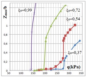
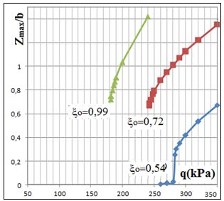
E3S Web of Conferences 281, 01026 (2021) https://doi.org/10.1051/e3sconf/202128101026 CATPID-2021 Part 1 a) b) c) d) Fig. 5. View graphical dependencies Zmax/b=f(q) for design models, when the deepening of the foundation is simulated by lateral surcharges: flexible stamp (a), absolutely hard stamp (b); recessed foundation: flexible stamp (c), absolutely hard stamp (d), for the plastic areas constructed on a mixed solution basis It follows from the analysis of these curves that in the case of using the Coulomb condition to construct the plastic deformations areas, the value of the first critical load qmax and the "speed" of depth development PA (Fig. 4) significantly depend on the value of the coefficient of lateral soil pressure о. When the intensity of the external load reaches a certain value, these "speeds" become approximately equal: the upper segments of the above curves become almost parallel. If the PA development process is considered under the conditions of the mixed problem [2; 3], then the quantity qmax at о=0,37 and о=0,72 differ by no more than 15%, and the "rate" of change in the value Zmax/b very insignificantly depends on the value о: the corresponding curves in each of Fig. 5a-d congruent and close in shape to straight lines. Let us note one more feature of the plastic areas development under the conditions of a mixed problem. Fig. 5c, d it is seen that under the load q=0 plastic areas already exist (have a specific depth), and with a subsequent increase in the intensity of the load, they disappear and then reappear. This is due to the fact that in these cases the stamp is located at the bottom of the trench, simulated by a rectangular cut in the FEM design scheme and ensuring the foundation deepening. It is known that with certain combinations of the physical and mechanical properties of the soil and the geometric parameters of the trench at its base, plastic areas can appear in the corners, which we observe in this study. An increase in the external load intensity is equivalent in its action to "backfilling" (surcharge) of the lower part of the trench, i.e., is decreased in its depth. This explains, as it were, the "disappearance" of plastic areas with an increase in the external load intensity to a certain value, and then, with a further increase in the load, their "re-emergence". We emphasize that the noted regularities are also observed with other physical and mechanical properties of the base, which can be seen from Fig. 6 below as an example. 6
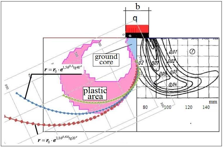
E3S Web of Conferences 281, 01026 (2021) https://doi.org/10.1051/e3sconf/202128101026 CATPID-2021 Part 1 a) b) Fig. 6. View graphical dependencies Zmax/b=f(q) for the design model, when the foundation deepening is simulated by lateral surcharges and the stamp is flexible for the "Coulomb" (a) and "mixed" (b) plastic areas at γ=18 кN/m3, Е= 25 МPа, φ=30о, с=0 kPа a) b) Fig. 7. Areas of plastic deformation at the base of an absolutely rigid (left) and flexible (right) stamp (a); curve of the form Zmax/b=f(ξо) at γ=18kN/m3, Е=25МPа, φ=30о, с=0kPа and q=300 kPа During the study, two more facts were established: taking into account the stiffness of the punch significantly affects the plastic areas development depth, both in the case of using the Coulomb plasticity condition for their construction, and a technique based on solving a mixed problem. An illustration of this statement is Fig. 7a, where, as an example, the plastic areas built on the basis of the technique [3-6] are shown - for the base at γ=18kN/m3, φ=21о, с=25kPа, Eо=25МPа, о=0,54, and the external load intensity takes on the values q1=263kPа, q2=307kPа, q3=352kPа. On the right, Fig. 7a, depicts the plastic areas formed under an absolutely rigid stamp, and on the left - under a flexible. In addition, it was found that, all other things being equal, the change in the value of the lateral pressure coefficient responds sensitively to the plastic areas’ development. There is such a meaning ξо, that for all other unchanged values of the design parameters, the value Zmax/b is minimal. An example is shown in Fig. 7b. Let us consider the results of laboratory experiments to determine the plastic areas in the base of the stamp, carried out by third-party authors, and compare them with the results of the calculations performed for the conditions of these experiments by the method [3-6] using the computer programs [7-8]. 7
E3S Web of Conferences 281, 01026 (2021) https://doi.org/10.1051/e3sconf/202128101026 CATPID-2021 Part 1 а) b) c) d) Fig. 8. The plastic deformation areas constructed for the operating conditions [9] by the method [3-6] for the loads q=0,9qmax (а), q=0,95qmax (b), q=qmax (c) at the value of the lateral pressure coefficient of the foundation soil ξо=0,43, the areas of plastic deformations obtained by the authors of [9] at P=Ppd (d) Fig. 8 (a, b, c) shows the areas of plastic deformations constructed for the operating conditions [9] by the method [3-6] for the loads q=0,9qmax (а), q=0,95qmax (b), q=qпmax (c) at the value of the lateral pressure coefficient of the foundation soil ξо=0,4 and φ=44о. Fig. 8d shows the figure presented in [9], corresponding to the values q=qпmax, ξо=0,4 and φ=44о. Comparing Fig. 8c and 8d, we state their almost complete identity. Let us give one more example. Fig. 9a shows the areas of plastic deformations (shear areas) obtained by the authors of [10] for sandy soil, and Fig. 9b shows the plastic area, constructed by us according to the method [3-6] for the work conditions [10] with the magnitude of the external influence intensity equal to its limiting value. Comparing the size, position and shape of these areas, we note that they almost completely coincide. а) b) Fig. 9. The plastic deformations areas (shear areas) obtained by the authors of the work [10] (а) and by the authors of this article (b) for clay soil And the last example. In [11], the authors used the methods of photogrammetry and photographic recording of the trajectories of displacements of sand particles to study the qualitative and quantitative aspects of the soil deformation process under the stamp. The tests were carried out in a tray with dimensions 600600145mm; A steel strip 145 mm long and 50 mm wide was used as a stamp. The base material was medium-sized quartz 8
E3S Web of Conferences 281, 01026 (2021) https://doi.org/10.1051/e3sconf/202128101026 CATPID-2021 Part 1 sand with a specific gravity =2,66 mN/m3, porosity coefficient eо=0,58 and the internal friction angle =35о. Fig. 10 (right part) shows the isolines of shear deformations during the settlement of the stamp, corresponding to the moment of the ultimate load onset. An isoline with a shear strain of 0.01 is identified by the authors of [11] with the boundary of the plastic deformation areas. On the left side of this figure, on the same scale, the area of plastic deformations is shown, built on the basis of the "mixed" solution [3-6], for the load corresponding to the KPI closure, formed under the edges of the stamp. This load, in our understanding, as noted above, is the maximum permissible. Fig. 10. Isolines of shear deformations during stamp settlement, corresponding to the moment of the onset of the ultimate load (on the right) (cited from [10]); the area of plastic deformations constructed according to the solution [1] for the work conditions [10] (on the left) Comparing these images, we can say that these plastic areas have similar shapes and approximately the same size; above KPI in both cases, there are soil zones that are in a “pre- limiting” state; the elastic soil core has the shape of an isosceles triangle with concave lateral sides, and a part of the boundary of the plastic area, built on the basis of the "mixed" solution, exactly coincides with the logarithmic spiral arc (segments of the green, blue and red curves). We note three circumstances that can be noted by analyzing Fig. 8; 9; 10: a) the elastic soil core has a symmetrical triangular shape and is located directly under the stamp; b) the volumes of soil located above the upper boundaries of the plastic areas (shear), in which there are no shear deformations at all stages of loading, i.e., in a pre-limiting (undisturbed) state (they are indicated by the number 1), are present in all figures; c) the lower boundaries of the plastic areas shown in Fig. 8-10, are approximated with a sufficient degree of accuracy by logarithmic spirals. 4 Conclusion Considering all of the above-said, the following conclusions can be drawn: 1. If we construct the areas of plastic deformations at the base of the strip foundation using the Coulomb plasticity condition, or applying the solution of a mixed problem, then, all 9
E3S Web of Conferences 281, 01026 (2021) https://doi.org/10.1051/e3sconf/202128101026 CATPID-2021 Part 1 other things being equal, the sizes of the “Coulomb” areas, the “speed” of their development and sensitivity to changes in the value of the lateral pressure coefficient of the soil will always be greater than in the alternative case. 2. The value of the maximum permissible load in both cases depends, all other things being equal, on the foundation stiffness and the soil lateral pressure coefficient. If the value of the ultimate load is taken to be its value corresponding to the closure of the plastic areas under the foundation, then the mixed solution of the theory of elasticity and the theory of soil plasticity problem gives higher (≥200%) the values of the latter. When constructing the plastic areas based on the Coulomb plasticity condition use, the latter are more sensitive to changes in the value о. 3. When finding the bearing capacity value of the strip foundation base, it is recommended to apply the solutions of the corresponding problems in the elastoplastic (mixed) formulation, since their results coincide with the experimental data with a sufficient degree of accuracy. References 1. C. Coulomb, Application des riles de maximus et minimis a quelques problemes de statique relatifs a L`architecture. Memories de savants strangers de L`Academlie des sciences de Paris (Paris, 1773). 2. G. Cagout, Eguilibre des massifs a frottemenet interne (Paris, 1934). 3. А.N. Bogomolov, Calculation of the bearing capacity of the structures’ foundations and the soil massifs stability in the elastoplastic formulation (Perm, PSTU, 1996). 4. А.N. Bogomolov, О.А. Bogomolova, Foundations, basements and soil mechanics 6, 7- 11 (2015). 5. А.N, Bogomolov, et. al., Construction and Geotechnics 8(1), 102-114 (2017). 6. О.А. Bogomolova, А.V. Zhidelev, Construction and Geotechnics 11(1), 5-19 (2020). 7. А.N. Bogomolov, and etc., FEA, Certificate of state registration of a computer program № 2015617889 from 23th July 2015. 8. А.N. Bogomolov and etc., Stability (stress-strain state), Certificate of state registration of programs for electronic computer № 2009612297 from 30th May 2009. 9. S.А. Elyizarov, М.V. Malyshev, Foundations, basements and soil mechanics 4, 2-5 (1993). 10. G.G. Boldyrev, М.V. Malyshev, Proceedings of universities. Construction 1, 126-129 (1987). 11. G.G. Boldyrev, Е.V. Nikitin, Foundations, basements and soil mechanics 1, 26-28 (1987). 10
You can also read