Aluminium Bi-fold Door Installation, Glazing, Operation and Maintenance Guide - Window Warehouse September 2020
←
→
Page content transcription
If your browser does not render page correctly, please read the page content below
Aluminium Bi-fold Door
Installation, Glazing, Operation
and Maintenance Guide

Window Warehouse September 2020
Index
Assembling Doors                          3-7                               Toe and Heeling
                                                                            Configurations      13-16

Installation Guide                        8-9                               Panel Retention       17

Panel Assembly                              10                              Operation Guide     18-19

Cill Joiner Instructions                    11                              Maintenance Guide   20-21

Glazing                                     12

2    Aluminium Bi-fold Door Installation, Operation and Maintenance Guide
Assembling Doors
Frame Assembly
 ASSEMBLY
  FRAME ASSEMBLY
                                                                     Frame Assembly Parts List (Per Corner)

                                                               Part No.             Description             Qty
                                                              P-06-100B             Outer frame              2
                                                                RX600        18.9mm Mechanical cleat         2
                                         P-06-100B
                                                                XA904             Narrow chevron             2
                                                             A-00-110A    Mechanical cleat tensioning block 4
                                                              T50000 - 2         Small joint sealant         -
                                                                T50003           Aluk sealant wipes          -
                                                            RX040 - RX041        Hinge back plate            -

                                                                     NB: Remember to seal each corner joint
                                                                               before final fix.

                                                                 Insert RX040/RX041 hinge backing plates into
                                                                      frame profile before joining corners

 RX600

    XA904
                                                     T50000-T50002

                                                                                     M3 Allen Key

                                        A-00-110A                     NB: Remove excess sealant with
                                                                        Aluk sealant wipes (T50003).

         R
                                                         www.window-warehouse.co.uk | Window Warehouse LTD.        3
             © 2017 Aluk S.A. All rights reserved
                                                                                    BSF70       10.01 01.08.2017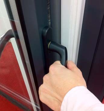
Assembling Doors
Bottom  Hinge to Frame Assembly
 BOTTOM HINGE TO FRAME ASSEMBLY

       35.5
      (2nd)

                                                                                                       Parts List
        35
       (3rd)                                                                    Part No.                Description                 Qty
                                                                               P-06-100B                Outerframe                   1
                                                                               P-06-200                 Softline Leaf                1
                                                                                 RX703                     Hinge                     1
                                                                                 RX040              Hinge Backing Plate              2
        25
                                                                                    -              M5 x 10 Csk Posi Screw            4
                                                                                    -        Ø4.2x25mm Self Tapping Csk Screw        2

    * See Below

        32

                                                                                       Final fixing position

                          * Dimension
         Hinge Standard Arrangement               23.5mm                                                                   RX040
                                                                                     RX703
             Heavy Duty Arrangement               27.5mm                                                                 P-06-200

                                                P-06-100B

                                                M5 x 10 Csk Posi
                                                Screw

                                              4.2 x 25mm Csk Posi
                                              S/Tap Screw

4       Aluminium Bi-fold Door Installation, Operation and Maintenance Guide

                R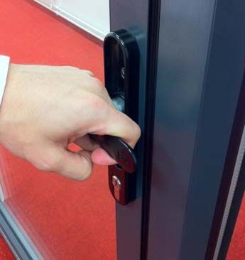
Assembling Doors
Top
  TOPHinge
     HINGE TOto Frame
              FRAME      Assembly
                    ASSEMBLY

                                                                12

   25                                                   * See Below
  (1st)

  35
 (3rd)                                                                                          Parts List
                                                                       Part No.                 Description                  Qty
                                                                      P-06-100B               Outerframe                      1
                                                                      P-06-200                Softline Leaf                   1
   35                                                                   RX703                  FSD Hinge                      1
 (2nd)                                                                                    Hinge Backing Plate
                                                                        RX040                                                 2
                                                                           -             M5 x 10 Csk Posi Screw               4
                                                                           -       Ø4.2x25mm Self Tapping Csk Screw           2

                                                                                Use BSD635 hinge jig for position

                    * Dimension
   Hinge Standard Arrangement     31mm                                                   Final fixing position
     Heavy Duty Arrangement       31mm                 P-06-100B

                                                       RX703

                                         4.2 x 25mm csk
                                         posi s/tap screw

                                             M5 x 10 Csk Posi
                                             Screw

                                                      RX040
                                                                                             P-06-200

                                                                                                                                  R

    BSF70      10.20 01.08.2017                                      www.window-warehouse.co.uk
                                                                                © 2017 Aluk S.A. All |rights
                                                                                                        Window    Warehouse LTD.
                                                                                                             reserved                 5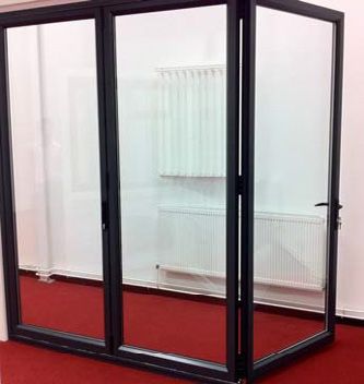
Assembling Doors
Bottom
  BOTTOM Hinge    Interlock
         HINGE INTERLOCK

        35
       (1st)                                                                                              Parts List
                                                                                Part No.                   Description                   Qty
                                                                                P-06-200                 Softline Leaf                    1
                                                                                P-00-211              Threshold Adaptor                   1
        35                                                                       RX714                                                    1
                                                                                                       Shootbolt Guide
       (3rd)
                                                                                 RX703                    FSD Hinge                       2
                                                                                    -               M5 x 10 Csk Posi Screw                4
                                                                                 RX040               Hinge Backing Plate                  2
                                                                                    -         4.2 x 25mm Csk Posi S/Tap Screw             2

        25                                                              * See Below
       (1st)

                          * Dimension
         Hinge Standard Arrangement           23.5mm
          Heavy Duty Arrangement              27.5mm
                                                                                           Final fixing position                       RX040

                                                                          P-06-200                                                 P-06-200

                                               M5 x 10 Csk
                                               Posi Screw

                                             4.2 x 25mm Csk
                                             Posi S/Tap Screw

                                                                                      RX703

                                                                                                                                               R

6    BSF70 Bi-fold
    Aluminium 10.22Door01.08.2017
                        Installation, Operation and Maintenance Guide                       © 2017 Aluk S.A. All rights reserved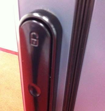
Assembling Doors
Top Hinge Interlock Assembly
        TOP HINGE INTERLOCK ASSEMBLY

*See Below                                              25
                                                        (1st)

                                                         35                          * Dimension
                                                        (3rd)
                                                                    Hinge Standard Arrangement           31mm
                                                                      Heavy Duty Arrangement             31mm

                                                          35                           Parts List
                                                        (2nd)
                                                                Part No.               Description               Qty
                                                                P-06-200                Softline Leaf             1
                                                                 RX713                Shootbolt Guide             1
                                                                 RX703                   FSD Hinge                1
                                                                    -              M5 x 10 Csk Posi Screw         4
                                                                 RX040              Hinge Backing Plate           2
                                                                    -        4.2 x 25mm Csk Posi S/Tap Screw      2

                                                                                            P-06-200

                                                                           RX713

                                      RX040

                         FSD Hinge
                         M5 x 10 Csk Posi
                         Screw

             R
                                                                www.window-warehouse.co.uk | Window Warehouse LTD.        7
                 © 2017 Aluk S.A. All rights reserved
                                                                                         BSF70         10.25 01.08.2017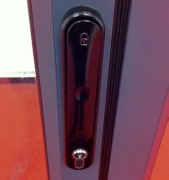
To check for squareness, measure the diagonals from corner to cor
                                                                              more than 1 to 2mm, if so adjusted the packing until the frame is sq
                                                                              The lay of the frame in to out can be checked by using a spirit level
                                                                              correct position of the frame might not be aligned with the original

Installation Guide                                                            good the plaster reveal around the frame on the internal wall as we

                                                                              Fixing Frames

                                                                              The first fixing must always occur within 150mm of each corner and
Fitting Frame To Aperture                                                       Foamfixings), the type and frequency depends on the expected a
                                                                              tighten
It is vitally important that the cill is laid flat and level to achieve the     Fixing foam
                                                                              Packing    willcan
                                                                                              bebe  used in conjunction
                                                                                                  required              with fasteners,
                                                                                                              at fixing points          but is not
                                                                                                                                 to prevent         an
                                                                                                                                                distortion of the
optimum performance. Jambs must be vertical in both planes, and                 alternative to screw fixing. Care must be taken not to  allow the
                                                                              where there is a possibility of moisture penetration around the fast foam
no twist or other distortion allowed. Prior to installing the frame, the        to come in contact with the painted finish, and as such the use of
opening should be checked to ensure that it is free of debris, and that         some form of masking tape would be advisable. Permanent staining
any projecting brickwork has been trimmed back.
                                                                              Foam
                                                                                will be caused if foam comes in contact with the frame.
Any damaged damp proof membranes should be replace or                           IMPORTANT        NOTE
additional membranes incorporated. When the opening was originally            Fixing foam can be     used in conjunction with fasteners, but is not an
                                                                                Always cap of seal fixings, especially when securing to any of
measured a suitable gap should have been allowed around the                   Care must be taken not to allow the foam to come in contact with t
                                                                                the Blyweert Beaufort range of cills / drainage trays.
perimeter of the frame, this will allow the frame work to be packed           of masking tape would be advisable. Permanent staining will be cau
to ensure that it is plumb and square within the opening. Ideally
the frame should be bedded on mortar. The frame can then be
positioned in the opening and held square by packing at the very
corners, taking care not to damage or deform the profile.
                                                                                                                                                     IMPORTAN
Tip
To check for squareness, measure the diagonals from corner to
corner, these diagonal dimensions should not differ by more than                        P-06-200
                                                                                        P-06-200
1 to 2mm, if so adjusted the packing until the frame is square within
the opening.
                                                                                                                                                IMPORTANT N
The lay of the frame in to out can be checked by using a spirit level
on the jambs. On replacement applications, the correct position of
                                                                                                                                                especially whe
                                                                                        P-00-211
                                                                                        P-00-211
the frame might not be aligned with the originals. This will require                                                                            Blyweertbeauf
some remedial work to make good the plaster reveal around the
frame on the internal wall as well as, any render externally.
                                                                                                                                                **
Fixing Frames                                                                                                                                   Alternative Fix
The first fixing must always occur within 150mm of each corner                             P-06-100
                                                                                           P-06-100
and at not more than 600mm centres (Do not over tighten fixings),                                                                       RX916
                                                                                                                                        RX916
                                                                                                                                                i.e. Through Th
the type and frequency depends on the expected applied loadings.                                                                                NB: Avoid leav
Packing will be required at fixing points to prevent distortion of the                                                                          as this may fou
                                                                                                                                                 NB:
frame. Drilled holes in the frame should be sealed where there is a
possibility of moisture penetration around the fastener.
                                                                              www.blyweertbeaufort.com               tel: 01633 29 40 40             fax: 01633

                                                                                      www.blyweertbeaufort.com                   tel:

8      Aluminium Bi-fold Door Installation, Operation and Maintenance Guide
Installation Guide
RX601
RX601
RX601
RX601
P-06-200 P-06-200
P-0
P-00-211 P-00-211
Installation Guide Sub Cill Installation P-0
Fixing A Drainage paths through the sub cill must be Fixing
free andA left un-obstr
P-06-100 RX600 RX600 P-06-100 RX600 RX600
On conservatory/dwarf walls only, an additional fixing ‘A’ must be
Sub Cill Installation
the sub cill. Seal under the head to prevent water ingress. Further
Drainage paths through the sub cill and must be free and left un- to secure the frame into the sub cill. Seal under the head to prevent
P-0
obstructed
AW542 by the sub structure or sealing. On conservatory/dwarf water ingress. Further seals should then be applied and sealed in suite.
AW542
walls only, an additional fixing A must be located as shown alongside
A: With cill B : With cill
concealed drainage face draina
(standard option) (alternative
No Cill Face Drainage With Cill Concealed Drainage (as standard)
C: No cill
Locking T-Handle face drain as standard
Lock each T-Handle before proceeding.
RX601
RX601
P-06-200 P-06-200
RX601
RX601
P-06-200
P-00-211 P-00-211
P-00-211
Fixing A Fixing A
P-06-100 RX600 RX600 P-06-100
P-06-100 RX600 RX600
RX916
AW542 AW542
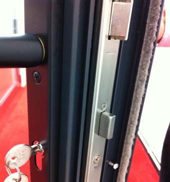
Hook Engagement
To lock, lift lever handle and turn key.
Issue 1A : 03/2013 C: No cill
face drain
mechanism and hardware.
RX601
RX601
P-06-200
RX601
RX601
P-06-200
P-00-211
P-00-211
P-06-100 RX600 RX600 Fixing A
P-06-100 RX600 RX600
AW542
RX916
www.window-warehouse.co.uk | Window Warehouse LTD. 9
Panel Assembly
Final Fix

Once glazed and adjusted use a 4.2 x 25mm self-tapping stainless steel screw to ensure
location of hinges and bogles (shown in green).

*Only fix after final glazing.

 Secondary Panel                                     Adjustment
 Once fixed repeat for remaining panels.             Adjust placement by sliding the backing
                                                     plate then re-tightening machine screw.

The 4.2 x 25mm self-tapping stainless steel screws are supplied in the installation pack with
this guide.

10     Aluminium Bi-fold Door Installation, Operation and Maintenance Guide
Cill Joiner Instructions
4 6 7
1 5 1
2
3
ITEM PART NUMBER DESCRIPTION
1 AW542 150mm x 25mm Drop Nose Cill
2 XA950 Universal Cill Spigot
3 XA951 Cill Nose Spigot
4 XA946 Cable Latch
5 XA952 Cable Hook
6 - Jointing Cable
7 N/A 3.5 x 12 Posi Pan S/Drill S/Tap Screw
XA950 Universal Cill Spigot is marked at 5° angular increments to allow for accurate cutting to
desired angle.
STAGE 1
3 (x2)
Position Cill Spigot (cut to desired angle) into Cill profile and slide
Cill Nose Spigot into the front edge Cill groove.
Hook Fixing Position
75
STAGE 2
Move the Cill sections in towards each other until the mitred
faces are touching.
STAGE 3 115
Cable Latch Fixing Position
Complete the Cill assembly by placing the Latch Cable over
the hook and lowering the Latch to form a secure connection.
INFORMATION CONTAINED IN THIS DRAWING IS THE EXCLUSIVE INTELLECTUAL PROPERTY OF BEAUFORT SECURE DESIGN LTD. IT MAY ONLY BE USED FOR THE PURPOSE TO
WHICH IT HAS BEEN SUPPLIED AND MUST NOT BE REPRODUCED, STORED OR DISSEMINATED TO THIRD PARTIES IN ANY WAY OR FORM WITHOUT THE WRITTEN PERMISSION OF
BEAUFORT SECURE DESIGN LTD. THE BEAUFORT POLICY OF CONTINUOUS IMPROVEMENT DETERMINES THE RIGHT TO MAKE MODIFICATIONS WITHOUT PRIOR WARNING.
www.window-warehouse.co.uk | Window Warehouse LTD. 11!v
v!gpsu!
!v
gpsu!
!gpsu!
v!gpsu!
gpsu!
!!gpsu!
bb e a u ffo rtt00 Advanced Plus
bb
be
ee
ea
aa
au
uu
uf
f o
o
f o
r
r
o rr
t t
0
t 0
0
Advanced
Advanced
Advanced
Advanced
Advanced
Plus
Plus
Plus
Plus
Plus
Glazing Range
Range
Range
Range
Range
Range Glazing
Glazing
Glazing
FSD
FSD
FSD FSD
FSD
FSD
Glazing
Glazing
BOTTOM
BOTTOM
BOTTOM GLASS
GLASS SUPPORT GLASS Glazing
SUPPORT ASSEMBLY BOTTOM GLASS SUPPORT
BOTTOM GLASSGLASS
SUPPORT
SUPPORT
SUPPORT GLASSGLASS
SUPPORT
SUPPORT
ASSEMBLY
ASSEMBLY
GLASS SUPPORT ASSEMBLY BOTTOM
BOTTOM
BOTTOM GLASS
GLASSGLASS
SUPPORT
SUPPORT
SUPPORT
BOTTOM GLASS SUPPORT GLASS SUPPORT ASSEMBLY BOTTOM GLASS SUPPORT
BOTTOM GLASS SUPPORT GLASS SUPPORT ASSEMBLY BOTTOM GLASS SUPPORT
cf!!!!gpsu!
bvbv
cf!!!!gpsu!
cf!!!!gpsu!
bvbv
cf!!!!gpsu!
cf!!!!gpsu!
bv
cf!!!!gpsu!
bv
Bottom
Place Glasspacker
bridge Supportononthe Glassbridge
Support Assembly BottompackersGlass to Support
Place
Placebridge
Place
bridgebridge
packer
packerpacker
ononthe
the thehinge
hinge
hingehinge
side side
sidealong
sidealong
along along
the the
the thePlace
Place
Placebridge
Place
bridgebridgepackers
packerspackers
packers 150mm150mm
150mm 150mm
from from
fromthe
fromthe
thecorner
thecornercorner
corneroppo‐oppo‐Use glazing
oppo‐oppo‐
Use
Useglazing
Use glazingglazing
packers
packers
packers to‘heel’
toto‘heel’
‘heel’
glass
‘heel’
glass
glassin
glassininplace.
inplace.
place.place.
StartStart
Start Start
Place
bottom bridge
bottom
Place bridge
bottom
and andpacker
vertical
packer
vertical
and on on
vertical
sections the
sectionshinge
thesections
hinge
150mm150mm
side
150mm side
from from
alongthe the
the the site
from Place
site
Placethe the
bridge
site bridge
hinge
thehinge
packers
hinge
side packers
side
of of
150mm
side
the ofthe150mm
panel
from
panel
the from the
the corner oppo‐
panel Use
at atUse
the
glazing
the at
bottom
the glazing
bottom
packers
bottom
hinge packers
hinge
to side
‘heel’
hinge
side to ‘heel’
glass
side glassStart
in place. in place.
bottom and
Place vertical
bridge sections
packer on the150mm
hinge from the the site the
side along Place hinge sidepackers
bridge of the 150mm
panel from the corner oppo‐at the Usebottom
glazinghinge sideto ‘heel’ glass in place. Start
packers
corner
along
bottom
corner the
and bottom
corner and vertical
vertical sections 150mmsections
from the corner
site the hingeopposite
side of thethe hinge side of the
panel Start athinge
at the bottom the bottom
side hinge side.
corner
bottom and vertical sections 150mm from the site the hinge side of the panel at the bottom hinge side
corner
150mm from the corner. panel.
corner BOTTOM GLASS SUPPORT GLASS SUPPORT ASSEMBLY BOTTOM GLASS SUPPORT
BOTTOM
BOTTOMBOTTOM
GLASS
GLASSGLASS
SUPPORT
SUPPORT
SUPPORT GLASS
GLASSGLASS
SUPPORT SUPPORT
SUPPORT ASSEMBLYASSEMBLY
ASSEMBLY BOTTOMBOTTOM
BOTTOM GLASS
GLASSGLASS
SUPPORT SUPPORT
SUPPORT
BOTTOM GLASS SUPPORT GLASS SUPPORT ASSEMBLY BOTTOM GLASS SUPPORT
BOTTOM GLASS SUPPORT GLASS SUPPORT ASSEMBLY BOTTOM GLASS SUPPORT
fax:fax: Issue
fax:fax: Issue
IssueIssue
fax: Page
fax: Issue
Page
Page :: : :
Page
Issue
Page :
Page :
www.blyweertbeaufort.com
www.blyweertbeaufort.com
www.blyweertbeaufort.com tel: fax:
www.blyweertbeaufort.com tel:
tel: tel: fax:
fax: fax: Is
Is
www.blyweertbeaufort.com tel: fax: Is
Bottom
Bottom
Bottompackers
packers
packershighlighted
highlighted
highlightedininRED
in RED REDsupport
support the the
support the PackPack
the
Packthe
theopposite
opposite
opposite
upperupper
uppercorner
cornercornerofof
of the the
thenon‐hinge
non‐hinge The
Theupper
non‐hinge The upper
www.blyweertbeaufort.com tel: packers
upper
packers
packersre‐distribute
re‐distribute
re‐distribute the
theweight
the weight
fax: weightofofthe
of the the
PP
Bottom
weight
Glass
Bottom packers
ofofthe
Supportin RED support the
highlighted
glass
PackGlass Support
the opposite Assembly
upper corner of the non‐hinge Bottom
The upper Glass
packers Support
re‐distribute the weight of the P
Bottom
weight packers
weight
of highlighted
glass in RED support the Packside
the ofofthe
thepanel
opposite upper corner of the non‐hinge glass
The upper back towards
packers the
theouter‐frame
re‐distribute the weight of the
Bottom ofthe glass
packers
the side
sideof
side
the panel panel glass back
glasstowards
back towards
the
theouter‐frame
outer‐frame
glass highlighted in RED Pack
the the
panelopposite upper corner of the The upper packers re-distribute the of the
weight
Bottomthepackers
glass highlighted in RED support the of
Packthe
thepanel
opposite upper corner of the non‐hinge glassThe
back towards
upper packers outer‐frame
re‐distribute the weight
weight of the side of glass back towards the outer‐frame
weight of the glass
support the weight of the glass. side of the panel
non-hinge side of the panel. glass back towards the outer‐frame
weight of the glass back towards the
outer-frame.
The bridge packers are included in the installation pack (4 per sash).
www.blyweertbeaufort.com
www.blyweertbeaufort.com
www.blyweertbeaufort.comtel:tel: fax: Issue
www.blyweertbeaufort.com tel: tel: fax:
fax:fax: Issue
IssueIssue
www.blyweertbeaufort.com tel: fax: Page
www.blyweertbeaufort.com tel:
www.blyweertbeaufort.com tel: fax: fax:
Issue
Page
Page :: : :
Page
Issue
www.blyweertbeaufort.com
www.blyweertbeaufort.com
www.blyweertbeaufort.com tel:
tel: tel: fax:
fax:fax: Issue
Issue Issue
Page : Issue
www.blyweertbeaufort.com tel: fax: Page : Issue Page
www.blyweertbeaufort.com tel: fax: Page
Page :: : :
Page
Issue
Page :
Page :
eaufort.com tel:tel:
ufort.com
beaufort.com fax: Issue
ufort.com tel: tel: fax:
fax:fax:
Issue
IssueIssue
ufort.com tel: fax: Page
eaufort.com tel: fax:Issue
Page
Page :: : :
Page
Issue
Page :
Page :
www.blyweertbeaufort.com
www.blyweertbeaufort.com
www.blyweertbeaufort.com
tel:tel: 01633
01633
tel: 01633
29 29
40
2940
40
4040
40 fax:
fax: 01633
01633
fax: 01633 294041
294041
294041 Issue: 01/11/2011
www.blyweertbeaufort.com tel: 01633 29 40 40 fax: 01633 294041 Issue:Issue:
Issue: 01/11/2011
01/11/2011
01/11/2011
www.blyweertbeaufort.com tel: 01633 29 40 40 fax: 01633 294041 Page
Issue: 01/11/2011
PagePage: 18
::18
www.blyweertbeaufort.com tel: 01633 29 40 40 fax: 01633 294041 Page 18: 18
Issue: 01/11/2011
Page : 18
12 Aluminium Bi-fold Door Installation, Operation and Maintenance Guide Page : 18ort0 Advanced Plus
beaufort0
Range FSD Advanced Plus
beToeaufRange
o r t 0 FSD Plus
Advanced
& Heel Type Configuration
Toe & Heel Type Configurations
1 FSD TYPE 2 Toe & Heel Type Configurations
Range FSD TYPE 3 FSD
FSD TYPE 1 FSD TYPE 2 FSD TYPE 3
Toe & Heel Type Configurations
FSD TYPE 1 FSD TYPE 2 FSD TYPE 3
FSD TYPE 4 FSD TYPE 5
FSD Type 1FSD TYPE 4 FSD Type 2 FSD Type 3
FSD TYPE 5
FSD TYPE 4 FSD TYPE 5
FSD Type 4 FSD Type 5
FSD TYPE 6
FSD TYPE 6
FSD TYPE 6
com tel: 01633 29 40 40 fax: 01633 294041
FSD Type 6 Issue: 01/11/2011
Page : 21
www.blyweertbeaufort.com tel: 01633 29 40 40 fax: 01633 294041 Issue: 01/11/2011
Page : 21
www.blyweertbeaufort.com tel: 01633 29 40 40 fax: 01633 294041 Issue: 01/11/2011
Page : 21
www.window-warehouse.co.uk | Window Warehouse LTD. 13forb eaufort0 Advanced Plus
tToe
0 & Heel
Advanced Plus
RangeType Configuration
FSD FSD
Range
FSD TYPE 7 FSD TYPE 8
FSD TYPE 7 FSD TYPE 8
FSD Type 7 FSD Type 8
FSD TYPE 9
FSD TYPE 9
FSD Type 9
www.blyweertbeaufort.com tel: 01633 29 40 40 fax: 01633 294041 Issue: 01/11/2011
ort.com tel: 01633 29 40 40 fax: 01633 294041 Issue: 01/11/2011 Page : 22
Page : 22
14 Aluminium Bi-fold Door Installation, Operation and Maintenance GuidebebToe
aeuafo
u
& r
f o
t 0
r
Heel t 0 Advanced
Advanced
Type Configuration
PlusPlus
Range
Range FSDFSD
bebaeuafo
urfot0rt0 Advanced
Advanced
PlusPlus
Range
Range FSDFSD
FSD11TYPE 11
FSD11TYPE 11
FSD13TYPE 13
FSD13TYPE 13
FSD TYPE
FSD TYPE
FSD TYPE
FSD TYPE
FSD Type 11
FSD Type 13
FSD10TYPE 10
FSD10TYPE 10
FSD12TYPE 12
FSD12TYPE 12
FSD TYPE
FSD TYPE
FSD TYPE
FSD TYPE
FSD Type 10
FSD Type 12
www.blyweertbeaufort.com
www.blyweertbeaufort.com
tel: 01633
tel: 01633
29 40 40
29 40
fax:40
01633
fax: 01633
294041294041 Issue: 01/11/2011
Issue: 01/11/2011
Page : 23
Page : 23
www.blyweertbeaufort.com
www.blyweertbeaufort.com
tel: 01633
tel: 01633
29 40 40
29 40
fax:40
01633
fax: 01633
294041294041 Issue: 01/11/2011
Issue: 01/11/2011
Page : 23
Page : 23
www.window-warehouse.co.uk | Window Warehouse LTD. 15Toe & Heel Type Configuration
b
beb
ba
e e
eu
a a
affu
u o
u
o ffr
o
r
o t
tr
r0
0t
t 0
0
Advanced
Advanced
Plus
Plus Advanced
Advanced
FSD
Plus
FSD
Plus
Range
Range Range
Range FSD
FSD
TYPE1515
TYPE1515
TYPE1717
TYPE1717
FSDTYPE
FSDTYPE
FSDTYPE
FSDTYPE
FSD
FSD
FSD
FSD
FSD Type 15
FSD Type 17
TYPE1414
TYPE1414
TYPE1616
TYPE1616
FSDTYPE
FSDTYPE
FSDTYPE
FSDTYPE
FSD
FSD
FSD
FSD
FSD Type 14
FSD Type 16
www.blyweertbeaufort.com
www.blyweertbeaufort.com
tel: 01633
tel: 01633
29 4029
4040fax:
4001633
fax: 01633
294041
294041 Issue:Issue:
01/11/2011
01/11/2011
www.blyweertbeaufort.com
www.blyweertbeaufort.com
tel: 01633
tel: 01633
29 4029
4040fax:
4001633
fax: 01633
294041
294041 Issue:Issue:
01/11/2011
01/11/2011
Page :Page
24 : 24
Page :Page
24 : 24
16 Aluminium Bi-fold Door Installation, Operation and Maintenance GuidebAdvanced
eauFSD
foPlus
rt0 Advanced Plus
Panel Retention
Range FSD
Bottom packers highlighted in RED support the Screw magn
Panel Retention weight of the glass
MAGNET LOCATION
MAGNET LOCATION MAGNET FITTING MAGNET FITTED
MAGNET LOCATION
30 150 30 150
www.blyweertb
Magnet Location Magnet Fitting Magnet
Located Fitted
at the top of connected panels
ded Magnet location
Bottom as above
packers highlighted in RED support the Screw magnet to door using screw provided Magnet location as above
Magnet location as above. Screw magnet to door using screw Located at the top of connected panels.
weight of the glass
provided.
MAGNET FITTED
www.blywe
The magnet and screw kit is supplied in the installation pack. A longer magnet is supplied in the kit for the master door leaf so the handle does
not foul on the adjacent door leaf.
fax: Issue
www.blyweertbeaufort.com tel: fax:
www.blyweertbeaufort.com Issue 29 4
tel: 01633
Page : Page :
Located at the top of connected panels
tel: fax: Issue
www.blyweertbeaufort.com tel: fax:
Page :
94041 Issue: 01/11/2011
www.blyweertbeaufort.com tel: 01633 29 40 40 fax: 01633 294041 Issue: 01/11/2011
Page : 19 Page : 19
www.window-warehouse.co.uk | Window Warehouse LTD. 17beaufort0 Advanced Plus
b
b e
e a
a u
u
beau fo f
f o
o r
r
r t
t
t
Range
Range
Range
0
0
0 Operation Guide
Advanced
Advanced Plus
FSD Plus
FSD
Advanced Plus
Operation
Operation Guide
Guide FSD
Operation Guide
Range
Range
Range TRAFFIC
TRAFFIC
Range
Range
DOOR
TRAFFIC DOOR
OPERATION
DOOR OPERATION
OPERATION
Operation
TRAFFIC HANDLE
Operation
TRAFFIC
Operation
TRAFFIC HANDLE
Operation
Operation
Guide
OPERATION
Guide
HANDLE OPERATION
OPERATION
Guide
Guide
Guide
TRAFFIC HANDLE OPERATION
TRAFFIC
TRAFFIC
FSD
FSD
DOOR OPENING
TRAFFIC DOOR
DOOR OPENING
OPENING
TRAFFIC DOOR OPENING
TRAFFIC DOOR OPERATION TRAFFIC HANDLE
TRAFFIC
TRAFFIC DOOR OPERATION TRAFFIC HANDLE OPERATION
OPERATION TRAFFIC
TRAFFIC DOOR
DOOR OPENING
OPENING
TRAFFIC DOOR
TRAFFIC DOOR OPERATION
DOOR OPERATION
OPERATION
TRAFFIC
TRAFFIC HANDLE
HANDLE OPERATION
OPERATION TRAFFIC
TRAFFIC DOOR
DOOR OPENING
OPENING
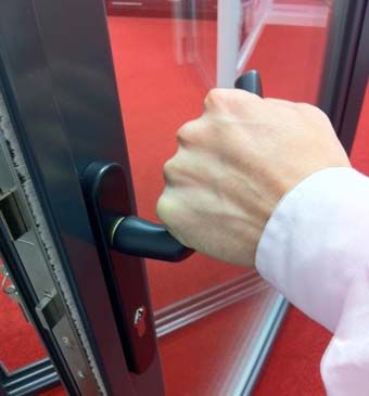
1. 2. 3.
Turn
Turn key clockwise to unlock Grip handle and push down to operate high traffic Open panel fully to allow the magnets to fix to
Turn key
key clockwise
clockwise to
to unlock
unlock Grip
Grip handle
handle and
and push
push down
down toto operate
operate high
high traffic
traffic Open
Open panel
panel fully
fully to
to allow
allow the
the magnets
magnets to
to fix
fix to
to
door
door handle
handle the
the adjacent
adjacent panel
panel
Turn key clockwise
Traffic Door to unlock
Operation door handleHandle
GripTraffic
handle and pushOperation
down to operate high traffic the
Openadjacent
panel
Traffic panelOpening
fully
Door to allow the magnets to fix to
Turn
Turn key
key clockwise
clockwise to
to unlock
unlock Grip
Grip handle
handle and
and push
push down
down to operate high traffic Open panel fully to allow the magnets to fix to
Turn
Turn
Turn keykey
key clockwise
clockwise
clockwise
HOLDING to to unlock.
to unlock
unlock
TRAFFIC DOOR OPEN
OPEN
door
Grip
Grip
door
handle
Grip handle
handle
handle
handle and and push
push down
UN‐LOCKING
and push down
UN‐LOCKING TTto
down
to operate
HANDLE
to operate
HANDLE
high
to release
operate high
high
traffic
traffic
traffic
Open
the
Open
Open
the
panel
adjacent
Open panel
panel
fully
panelpanel
fully
fully
to
fully
to
DISENGAGE
to
DISENGAGE
adjacent panel
allow
allow
allow
the
to allow
the
the
magnets
magnets
SHOOTBOLTS
magnets
SHOOTBOLTS
to
the magnets
to
to
fix
fix
fix
to
to
to
to
HOLDING
HOLDING TRAFFIC DOOR
TRAFFIC DOOR OPEN door handle
handle UN‐LOCKING T HANDLE the adjacentDISENGAGE
adjacent panel
panel SHOOTBOLTS
door the
fixadjacent
to theDISENGAGE
adjacent panel.
doorlocks on traffic
handle door handle.
UN‐LOCKING T HANDLE the panel SHOOTBOLTS
HOLDING TRAFFIC DOOR OPEN UN‐LOCKING TT HANDLE DISENGAGE SHOOTBOLTS
HOLDING
HOLDING TRAFFIC DOOR OPEN UN‐LOCKING HANDLE DISENGAGE SHOOTBOLTS
HOLDING TRAFFIC
HOLDING TRAFFIC DOOR
TRAFFIC DOOR OPEN
DOOR OPEN
OPEN
UN‐LOCKING
UN‐LOCKING TT HANDLE
HANDLE DISENGAGE
DISENGAGE SHOOTBOLTS
SHOOTBOLTS
4. 5. 6.
Magnets
Magnets protect
protect and
and fix
fix traffic door panels to Push T‐Handle to release Rotate handle clockwise 180* to disengage
Holding
Magnets Traffic
protect fix traffic
andDoor Open
traffic door
door panels
panels to
to Push T‐Handle
T‐Handle to
Unlocking
Push release
toT-Handle
release Rotate
Rotate handle
handle clockwise
Disengage Shootbolts
clockwise 180*
180* toto disengage
disengage
adjacent
adjacent panels
panels shootbolts
shootbolts fully
fully
Magnets
adjacent
Magnets protect
panels
protect andand fix traffic
fix traffic doordoor
panels to Push
Push T-Handle
T‐Handle to release.
to release Rotate handle
shootbolts
Rotate clockwise
fullyclockwise
handle 180*180* to
to disengage
Magnets
Magnets protect
protect and
and fix
fix traffic
traffic door
door panels
panels to
to Push
Push T‐Handle to release Rotate handle clockwise 180* to disengage
panels panels
adjacent
Magnets
Magnets to adjacent
protect and
TT HANDLE
protect panels.
and fix
fix traffic
traffic door
door panels
OPERATION panels to
to Push T‐Handle
Push T‐Handle
to
to release
T‐HandleUN‐LOCKING
to release TT HANDLE
UN‐LOCKING
release HANDLE Rotate
Rotate
Rotate
handle
disengage
shootbolts fully
handle
handle
clockwise
shootbolts
clockwise
OPENING
clockwise
180*
fully.
180*
FOLDING
180*
to
to
to
disengage
disengage
PANELS
disengage
adjacent
adjacent T HANDLE
panels
panels HANDLE OPERATION
OPERATION UN‐LOCKING T HANDLE shootbolts OPENING
shootbolts OPENING
fully
fully FOLDING PANELS
FOLDING PANELS
adjacent panels
adjacent panels shootbolts fully
shootbolts OPENING
fully
T HANDLE OPERATION UN‐LOCKING T HANDLE FOLDING PANELS
TT HANDLE
HANDLE OPERATION UN‐LOCKING T HANDLE OPENING FOLDING PANELS
7. HANDLE OPERATION
TT HANDLE OPERATION
OPERATION 8.
UN‐LOCKING
UN‐LOCKING TTT HANDLE
UN‐LOCKING HANDLE
HANDLE 9.
OPENING
OPENING FOLDING
OPENING FOLDING PANELS
FOLDING PANELS
PANELS
T Handle Operation Unlocking T-Handle Opening Folding Panels
Push
Push the
the T‐Handle
T‐Handle back
back into
into the
the frame before Ensure the ‘Un‐locked’ symbol is at the top before Slide panels together
Push
Push thethe T-Handle
T‐Handle backback the frame
intointo before
the frame
frame before Ensure
Ensure the
Ensure ‘Un‐locked’
the the
‘Un‐locked’ symbol
‘Unlocked’ is
is at
symbol
symbol at the
is attop
the thebefore
top before Slide
Slide panels
Slide
panels together
panels together.
together
operating
operating doors
doors opening
opening doors
doors
before
operating
Push
Push
operating
doors back
the T‐Handle
the
doors.
into the frame before top
opening
Ensure before
doors
the opening
‘Un‐locked’ doors.
symbol is at the top before Slide panels together
Push the T‐Handle
operating
Push T‐Handle back into
doors back into the
the frame
frame before
before Ensure
Ensure
opening
the
the ‘Un‐locked’
‘Un‐locked’
doors
symbol
symbol is
is at
at the
the top
top before
before Slide
Slide panels
panels together
together
Push the
the T‐Handle
operating
operating doors back
T‐Handle
doors back into
into the
the frame
frame before
before Ensure
Ensure the
opening
openingthe ‘Un‐locked’
‘Un‐locked’ symbol
doors
doors symbol is
is at
at the
the top
top before
before Slide
Slide panels
panels together
together
www.blyweertbeaufort.com
operating doors
www.blyweertbeaufort.com tel:
tel: 01633 29 40
opening 40
doors fax: 01633 294041 Issue: 01/11/2011
operating doors
www.blyweertbeaufort.com tel: 01633
01633 29 29 40
40 40
opening doors fax:
40 fax: 01633
01633 294041294041 Issue:
Issue: 01/11/2011
01/11/2011
Page :: 5
Page 5
www.blyweertbeaufort.com tel: 01633 29 40 40 fax: 01633 294041 Page
Issue: 01/11/2011:5
18 Aluminium Bi-fold Door Installation,
www.blyweertbeaufort.com
www.blyweertbeaufort.com tel:
tel: 01633
01633Operation
29 and
29 40Maintenance
40 40
40 fax:fax:Guide
01633
01633 294041294041 Issue: 01/11/2011
www.blyweertbeaufort.com Issue: 01/11/2011
Page : 5
www.blyweertbeaufort.com tel: tel: 01633
01633 29 29 4040 4040 fax:fax: 01633
01633 294041294041 Issue: 01/11/2011
Issue: 01/11/2011
Page :5
Page
Page ::: 5
5
5
Pageb
b
b
bbe
e
e
eea
a
a
aau
u
uuf
f
ffo
o
oo r
r
r
rtt
t
t00
0
0
Advanced
Advanced
Advanced
Advanced
Advanced
Plus
Plus
Plus
Plus
Plus
b e a u
Operation f o r t 0 continued
Guide
Range
Range
Range
Advanced
FSD
FSD
FSD
FSD
FSD
FSD
Plus
Range
Range
OPEN POSITION CLOSING DOOR LOCKING T‐HANDLE
OPEN
OPEN
OPEN POSITION
POSITION
POSITION CLOSING
CLOSING
CLOSING DOOR
DOOR
DOOR LOCKING
LOCKING T‐HANDLE
T‐HANDLE
LOCKING T‐HANDLE
OPEN POSITION
OPEN POSITION CLOSING
CLOSINGDOOR
DOOR LOCKINGT‐HANDLE
LOCKING T‐HANDLE
10. 11. 12.
Open Position Closing Door Locking T-Handle
Stack
Stack thethe
Stack
the panels
panels together
panels
together for
together max
forfor clear
max
max opening
clear
clear opening Reverse
opening previous
Reverse
Reverse steps
previous
previous to to
steps
steps close
to door
close
close door Lock each
Lock T‐Handle
each before
T‐Handle proceeding
before proceeding
Stack the
Stack panels
the panelstogether
together for max
for max clear Reverse previous steps to door
close
door door.
Lock
Lockeach T‐Handle
each before
T-Handle proceeding
before proceeding.
Stack the panels together for max clearclear opening Reverse
opening Reverse previous
previous steps
steps to close
to close door Lock
Lock each
each T‐Handle
T‐Handle before
before proceeding
proceeding
opening. HIGH
Stack the panels
HIGHtogether
HIGHTRAFFIC for
TRAFFIC
TRAFFIC max
HANDLE clear
HANDLE
HANDLE opening Reverse previous
LATCHsteps
LATCH
LATCH to close
ENGAGEMENT
ENGAGEMENT
ENGAGEMENT door Lock each T‐Handle
High Traffic
HOOK
HOOK before
Handle
ENGAGEMENT
HOOK proceeding
ENGAGEMENT
ENGAGEMENT
HIGH HIGH TRAFFIC
TRAFFIC HANDLEHANDLE LATCH
LATCH ENGAGEMENT
ENGAGEMENT HOOKENGAGEMENT
HOOK ENGAGEMENT
HIGH TRAFFIC HANDLE LATCH ENGAGEMENT HOOK ENGAGEMENT
13. 14. 15.
LiftLift
thethe
high traffic
high traffichandle
handlewhen thethe
when door
dooris is Lifting thethe
Lifting handle operates
handle thethe
operates latch
latch ToTo
lock, liftlift
lock, lever
lever handle and
handle turn
and keykey
turn
Liftthethe
Lift high
the traffic
high traffichandle when the door Lifting the handle operates the
latchlatch. To lock, liftlift lever handle and turn key.
closed
Liftclosed to engage
high
to engage lockshandle
locks
traffic handle when
when the the
doordoor
is is Lifting
Lifting thethe handle
handle operates
operates thethelatch To
To lock,
lock, lift lever
lever handle
handle and
and turn
turnkey
key
isthe
Lift
closedclosed
closed
high to engage
to engage
traffic
to engage handle
locks locks.
lockswhen the door is Lifting the handle operates the latch To lock, lift lever handle and turn key
Lift the high traffic handle when the door is Lifting the handle operates the latch To lock, lift lever handle and turn key
closed
Latch to engage
Engagementlocks Hook Engagement
closedFailure
to engageto locks
Failure to correctly operate thefolding
correctly operate the foldingsliding
slidingdoor
doorsystem
systemcancancause
causedamage
damagetotothetheoperating
operatingmechanism
mechanism
Failure
Failure to correctly
to correctly operate
operate thethe folding
folding slidingdoor
doorsystem
systemcan cancause
causedamage
damage toto the
the operating
operating mechanism
and
andhardware.
hardware. This
Thiscancancause
cause the
the doortosliding
door tofail.
fail. mechanism
FailureFailure
to
and and to correctly
hardware.
correctly
hardware.
Failure operate operate
This
the can
folding
This operate
to correctly can cause the
cause
sliding
the
folding
the the
door sliding
door
system
door to
folding to
can door
fail.
cause system
damage to can
the cause damage
operating to
mechanism the
and operating
hardware.
fail. door system can cause damage to the operating mechanism
sliding
mechanism
andcause
This can hardware.
the door This
to failcan cause
and may the door
invalidate your to fail.
guarantee.
and hardware. This can cause the door to fail.
www.blyweertbeaufort.com
www.blyweertbeaufort.com tel:
tel:01633
0163329
2940
4040
40 fax: 01633
fax: 294041
01633 294041 Issue:
Issue:01/11/2011
01/11/2011
www.blyweertbeaufort.com tel: 01633 29 40 40 fax: 01633 294041
www.window-warehouse.co.uk | Window Warehouse
Issue: 01/11/2011
LTD.
Page : 19
6
Page :6
www.blyweertbeaufort.com tel: 01633 29 40 40 fax: 01633 294041 Page : 6
Issue: 01/11/2011
www.blyweertbeaufort.com tel: 01633 29 40 40 fax: 01633 294041 Issue: 01/11/2011
Page : 6Maintenance Guide
General Maintenance Locks & Hardware
● The door surfaces and inner chambers should be cleaned using All locking mechanisms should be kept free of dirt and grime and
warm soapy water or a mild diluted detergent. The surfaces lubricated with light machine oil such as 3 in 1 or WD40. Locking
should be cleaned using a soft cloth, sponge or a soft natural parts exposed when the door is open including strike/face plates,
bristle brush. All areas to be thoroughly rinsed and dried locking cams and hook bolts should be wiped clean of residue
after cleaning. lubricant and grime. These mechanisms should then be lubricated
using a light machine oil. Locking keeps should be lubricated with
Polyester Powder Coating Polyester powder coat paint is an organic
petroleum jelly from time to time. Always ensure excess oil is
finish that requires regular cleaning and maintenance to ensure it
wiped away.
keeps its decorative and protective qualities.
One year after installation and thereafter annually, the moving parts of
The frequency of cleaning depends on such factors as:
locking mechanisms should be lubricated with light machine oil as 3 in
1. The building’s surrounding environment (for example,
1, or WD40.
marine alkaline, acid. Industrial etc.)
2. The varying levels of atmospheric pollution, Handles may be cleaned with warm soapy water or a mild diluted
3. The prevailing wind direction, detergent using a soft cloth or sponge. It is important to thoroughly
4. Exposure to airborne debris such as sand or salt, which may cause rinse and dry the hardware after cleaning.
erosive wear.
Pivot points of handles should be lubricated periodically with light
Cleaning frequency also depends on the desired standard of machine oil such as 3 in 1 or WD40.
appearance and also the need to remove deposits, which could cause
The tightness of all fixing screws or rivets should be checked
damage after prolonged contact with the finish.
periodically. One year after installation and thereafter annually.
In an industrial environment, the normal interval between cleaning
Over tightening of handle fixing screws can put too much strain on
should not be more than every three months, Where there is a
the locking mechanism’s gearbox and impair the function of the lock.
high degree of industrial pollution or a hazardous atmosphere, the
Windows and doors which are not in frequent use should be opened
periods between cleaning should be reduced. If the atmosphere is
and maintained.
non-hazardous (for example in rural or normal urban locations),
the period between cleaning can be extended to a maximum of 18
months (or more frequently if heavy soiling occurs), Where a site is
subjected to any unusual environment factors, or is close to salt water,
your installer should be consulted for specialist advice.
20 Aluminium Bi-fold Door Installation, Operation and Maintenance GuideMaintenance Guide continued
Condensation This may result in trapped water vapour and increasing problems
with condensation. Condensation is best controlled by ventilation
Water vapour is continually present in the atmosphere and in the
and this is achieved by opening windows, fitting extraction units or
home this natural water content is increased by day-to-day activities
by fitting wall vents to provide airflow. Some heat should always be
which create steam such as cooking, bathing, washing, boiling
maintained in the building during cold weather.
water etc.
The temperature may be increased in areas where condensation
This water vapour is undetectable when carried in warm air, but it
is a particular problem. If possible, internal doors to kitchens and
condenses into water droplets when it comes into contact with cold
bathrooms should be kept closed and sealed against draughts
surfaces such as glass. Normally, water vapour is controlled through
to prevent excessively moist air being transferred to other areas.
natural ventilation via airbricks and chimneys etc. but conservation
Bedroom windows should have night ventilation facilities to provide
measures have lead to more efficient sealing of buildings.
air circulation. Curtains should be a minimum of 150mm away from
the door to ensure airflow, with suitable gaps.
www.window-warehouse.co.uk | Window Warehouse LTD. 21Window Warehouse Ltd Head Office: Dragon Industrial Estate, Fitzherbert Road, Farlington, Portsmouth, Hampshire PO6 1SQ Tel: 023 9232 7744 Fax: 023 9232 6611 E-mail: info@window-warehouse.co.uk www.window-warehouse.co.uk
You can also read