Installation Guide - FD30 Concealed Trims January 2021 | Revision 001 - Sliding Pocket Doors
←
→
Page content transcription
If your browser does not render page correctly, please read the page content below

Installation Guide

FD30 Concealed Trims
      January 2021 | Revision 001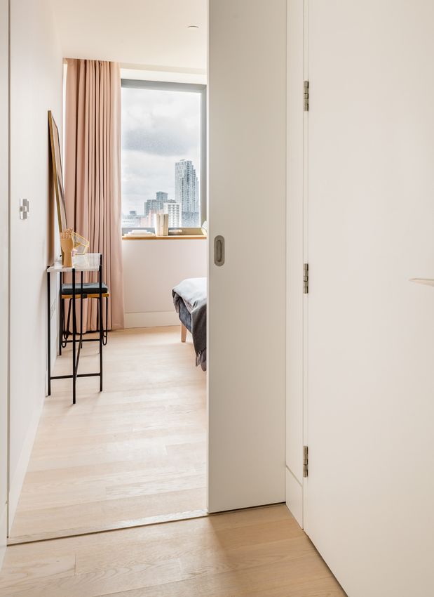
3

            Thank you for choosing Enigma                                                                                                       Getting started
         To ensure the installation process is simple and efficient,                                                                            Before you start installation ensure you
             we recommended you read this guide in full first.                                                                                  have read and understood the instructions.
        Specific tools are also required to complete the installation:

                                                                                                                                                DELIVERY

                                                                                                                                                The Enigma pocket door system will be delivered in two boxes.
                      Pencil                      Tape Measure                          Knife                     Hex Keys (metric)             One is the pocket frame and the other is the trim surround.

                                                                                                                                                If a door leaf has been ordered this will come separately.

               Hacksaw / Tin-snips                  Laser Level               Cordless Screwdriver                Power Chop Saw

Fire certification guidance                                                                                                    IMPORTANT

If fitting a fire rated lock refer to the Global Assessment for intumescent detail or contact Selo.

Flush door handles - Based on the test evidence cited within FEA/F97097 Revision G which permits the machining
of the Halspan 30 Prima/Optima door core to a minimum thickness of 26mm in order to achieve a paneled door
appearance, flush door handles may be fitted subject to the restrictions below:

1. Where handles are fitted back to back, handle thickness is                  3. Handle dimensions are limited to a maximum of 200mm in
   limited to 9mm.                                                                height and width at the thicknesses shown above.

2. Where handles are staggered between the two leaf faces a                    4. Handles must be fitted a minimum of 125mm from leaf edges.
   maximum handle thickness of 15mm is permitted, the handle
                                                                               5. The pocket formed to receive the handles must be lined with
   pockets must be separated by a minimum of 100mm of leaf
                                                                                  1mm thick Interdens. Refer to the Global Assessment for
   core material.
                                                                                  intumescent detail or contact Selo.

                 © 2019 by Selo. All rights reserved. Selo reserves the right to alter specification and designs without prior notice.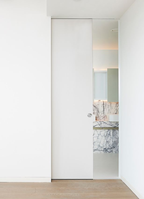
FD30 C   |   KIT CONTENTS                                                                                                                       5

                                                                            SYSTEM COMPONENTS

FD30 C frame kit
Familiarise yourself with components included. All fixings will
come pre-packaged to suit your specific project requirements.

FRAME FIXINGS
                                                                                   Base Channel           Head Channel      Leading Edge Jamb

               Type-1                       Type-2               Type-3         Intermediate Jamb         Timber Insert       Remote Stop
19mm self drilling pan head screw        40mm screw            50mm screw

               Type-4                       Type-5                            Door Guide Pin & Channel   Sliding Gear Set
             30mm screw             25mm self drilling screw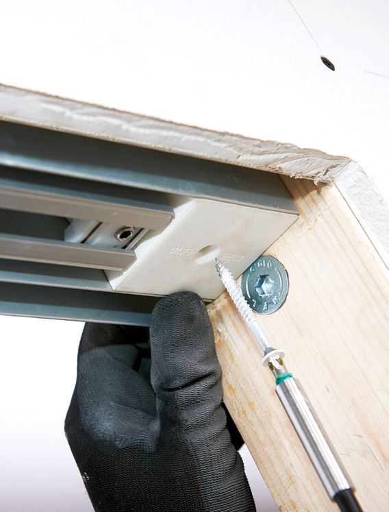
FD30 C   |   W A L L C O N S T R U C T I O N P R E PA R AT I O N                                                   7

Wall construction preparation
The Enigma system can be fitted to steel or timber
studwork partitions. If using steel you must ensure the
head stud is strong enough to take the door weight.

IMPORTANT INSTALLATION NOTES

1. Studwork size
The studwork size required is 94mm. If using steel studs a 94mm head
and base track and 92mm uprights should be used.

2. Steel studs
                                                                                 Bespoke
If using steel studs, timber inserts are required within the studs to
provide additional strength.
                                                                              requirements?
                                                                             Enigma can be customised to suit
                                                                             bespoke projects. In principle, the
4. Allow for Accessories                                                      installation process remains the
                                                                             same, however certain installation
If you are using a soft closer, touch latch or simultaneous opening
                                                                                  dimensions may differ.
mechanism ensure you familiarise yourself with these instructions first.

                                                                              Please contact the Selo team to
                                                                            discuss your bespoke requirements.
5. Self-supporting Head
For situations in high rise buildings where you cannot fix to the ceiling
                                                                              020 3880 0339
or soffit then use the Enigma Self-supporting Head installation detail.

Follow standard Enigma instructions to calculate your studwork
structural opening and add the following dimensions: Width +92mm
and Height +44mm. Refer to the specific Self-supporting Head
installation instructions for further details.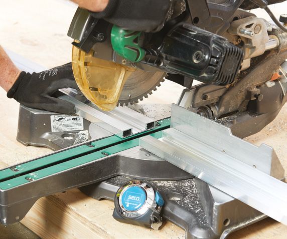
FD30 C    |   W A L L C O N S T R U C T I O N P R E PA R AT I O N                                                                                                                                                 9

                                                                                                                                                1   STRENGTHEN HEAD

FD30 C calculations                                                                                                                                 When constructing your stud partition, please
                                                                                                                                                    ensure the head is strong enough to take the
IMPORTANT                                                                                                                                           weight of the sliding door that will hang from it.
If using a Simultaneous Opening mechanism the door leaf needs to be reduced in height by 5mm.
If you are using the Self-supporting Head detail follow standard Enigma instructions to calculate your
studwork structural opening and add the following dimensions: Width +92mm and Height +44mm

Ensure you refer to the specific Self-supporting Head installation instructions for further details.

OPENING CALCULATIONS

                                                                                     Single Door
                                                                                     Structural opening width = x2 Door leaf width +33mm

                                       ›                                             Structural opening height = Door leaf height +77mm

                                                                                                                                                2
         FROM KNOWN                                   CALCULATE                      Double Doors
                                                                                     Structural opening width = x4 Door leaf width +32mm            CHECK SIZE WITH SCHEDULE
         Door dimensions                          Structural opening
                                                     dimensions                      Structural opening height = Door leaf height +77mm

                                                                                                                                                    When forming the structural opening, please
                                                                                     Single Door
                                                                                                                                                    ensure you are working to the correct opening
                                                                                     Clear opening width = Door leaf width -75mm

                                       ›                                             Clear opening height = Door leaf height -18mm
                                                                                                                                                    size provided on the door schedule.

         FROM KNOWN                                   CALCULATE                      Double Doors
                                                                                                                                                    IMPORTANT
                                                                                     Clear opening width = x2 Door leaf width -90mm
         Door dimensions                             Clear opening                                                                                  If using a self closer then please refer to the self closer
                                                      dimensions                     Clear opening height = Door leaf height -18mm
                                                                                                                                                    installation instructions.

                                                                                     Single Doors
                                                                                     Door width = Structural opening width -33mm ÷ 2

         FROM KNOWN
                                       ›              CALCULATE
                                                                                     Door height = Structural opening height -77mm

                                                                                     Double Doors

                                                       Door width                    Door width = Structural opening width -32mm ÷ 4
       Structural opening
          dimensions                                   and height                    Door height = Structural opening height -77mm

                                                                                     Single Door
                                                                                                                                                3   LEVEL-UP

                                                                                     Door width = Clear opening width +75mm

         FROM KNOWN
                                       ›              CALCULATE
                                                                                     Door height = Clear opening height +18mm

                                                                                     Double Doors
                                                                                                                                                    Ensure the opening is square and plumb.

                                                                                     Door width = Clear opening width +90mm ÷ 2                     IMPORTANT
          Clear opening                                Door width
           dimensions                                  and height                    Door height = Clear opening height +18mm                       We strongly recommend the use of a laser level for setting out.

                                                                                     Single Door

                                       ›
                                                                                     Base channel width = Door leaf +5mm

         FROM KNOWN
                                                                                     Double Doors
                                                      CALCULATE
                                                                                     Base channel width = Door width -12mm from centre of kit
         Door leaf width                              Base channel
                                                       dimension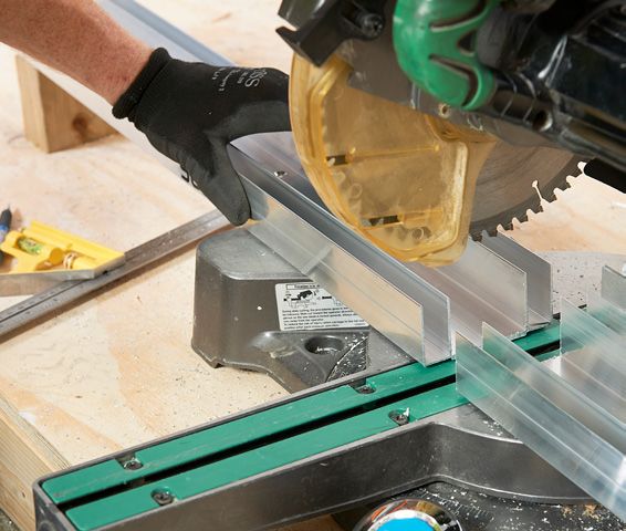
FD30 C | F R A M E I N S TA L L AT I O N 11
3 INSERT THE REMOTE STOP
A) Frame installation Add after groove in the track ‘as shown
on photo. The white plastic clip needs to
be located at the rear of the pocket, the
opposite end of the track from that used to
IMPORTANT
mark the 75mm line on the Head channel.
If you are using the Self-supporting Head detail please refer to the specific instructions.
IMPORTANT
1. If you are using the soft close mechanism, please
1 PREPARE HEAD CHANNEL & SLIDING TRACK refer to soft closer instructions before proceeding.
2. If using any of the following devices then please do
not insert the remote stop:
Single doors
1a Cut the Head channel to suit the › Soft Close & Open
› Touch Latch
structural opening width.
1b Remove the Remote stop, then cut the
1a sliding top track to the structural opening
width, less 80mm.
Double doors
3a
Measure the structural opening width, divide
in half and cut two head channels to that
length. Cut the sliding track 40mm less than
1b
the head channel length.
4 FIT THE HEAD CHANNEL AND TOP TRACK
Single doors
4a Put the Head channel in place and fix using
2
Type-2 screws. The end with 75mm marked
HEAD CHANNEL PREPARATION
butts against the strike stud.
4b Line the top track with the pilot drilled holes
Single doors Double doors
and fix using Type-3 screws. Only use the silver
2a Mark 75mm from Mark 30mm from
Type-3 screw provided to secure the track into
the end of the one end of both
place - Use of a larger screw will prevent the
head channel. head channels.
Remote stop from sliding freely within its groove.
It will be necessary to slide the Remote stop
back to access all the fixing holes in the track.
2b Line the end of the top track with the
mark and pilot drill the holes through the Double doors
Head channel. Butt the ends of the Head channels marked
30mm from the end together in the centre of the
IMPORTANT
structural opening width.
Ensure the groove in the centre of the track and the
head channel line up as shown.
2a 2b 4a 4b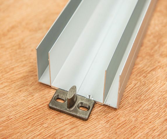
FD30 C   |   F R A M E I N S TA L L AT I O N                                                                                                                                         13

                                                    5   CALCULATE LENGTH OF BASE CHANNEL
                                                                                                                      6   LINING UP & FIXING BASE CHANNEL

                                                        Single doors                                                      Place the Base channel on the floor between the
                                                        To accurately determine the location of the Base                  line marked in step 5 and the rear stud.
                                                        channel, you need to refer to the ‘Base channel
                                                        position calculations’ below, relevant to your                    At this stage it is vital that care is taken to ensure
                                                        specific trim type. (The trim type is shown on the                that the centre line of the Base channel is
                                                        main box label). Measure this dimension back                      secured directly underneath the centre line of
                                                        from the strike stud and mark it on the floor.                    the track above. Any deviation in this alignment
                                                                                                                          will result in misaligned doors and trims.

                                                        Double doors                                                      Secure to the ground with Type-2 fixings.
                                                        Transfer the centre of the structural opening
                                                        width onto the floor. Calculate your door
                                                        leaf width for your specific kit type using the

                                                                                                                      7
                                                        formula’s shown on the left. Measure this
                                                                                                                          CUT LEADING EDGE & INTERMEDIATE JAMB
                                                        dimension back from the centre line and mark
                                                        the floor at this point. From this second mark
                                                        measure back to the rear stud and the base                        Cut the Leading edge jamb and
                                                        channel to that length.                                           Intermediate jamb 15mm less than the
                                                                                                                          structural opening height.

                                                        Once you have calculated the length cut the
                                                        base channel to this dimension cutting off the
                                                        end with the notch in.

                                                        Line the end of the Base channel with the mark
                                                        made on the floor, ensure that it is in line and
                                                        plumb with the head channel and fix into place
                                                        using Type-2 screws.

Base channel
Position calculations                                   IMPORTANT
                                                                                                                      8   CUT & FIT INTERMEDIATE TIMBER INSERT

                                                        If you are using a touch latch or a self closer you need to
                                                                                                                          Cut the intermediate Timber insert 100mm
FD30 Concealed Trim (C FR)                              make sure you have added the extra width needed.
                                                                                                                          shorter than the aluminium jamb and slide the
Single = Door width +5mm
                                                                                                                          insert into the Intermediate jamb so it sits
Double = Door width -12mm from centre line of kit
                                                                                                                          50mm from each end.

                                                                                                                          IMPORTANT
                                                                                                                          When using door leafs wider than 926mm the kit will be
                                                                                                                          supplied with extra intermediate jambs to be fitted equally
                                                                                                                          space within the pocket width.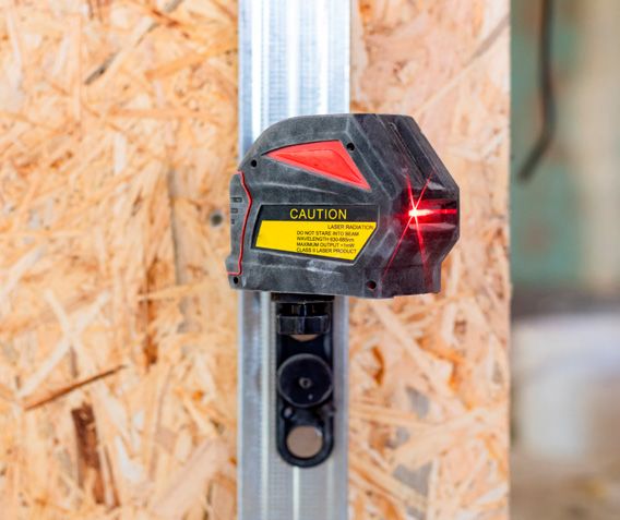
FD30 C   |   F R A M E I N S TA L L AT I O N                                                                                                                                              15

                                               9    FIT POCKET SIDES & FIX THE JAMB
                                                                                                                          11   FIT THE PACKER

                                                    9a Slide the Intermediate jamb into the                                    In order to support the pocket sides before
                                                    Head channel and Base channel with the                                     plasterboarding, insert the pocket packer into
                                                    Timber inserts facing out so it sits centrally                             the pocket as shown.
                                                    in the pocket. Fix using Type-1 screws.

                                                    9b Slide the Leading edge jamb into Base
                                                    channel with notched end at the top, so the
9a
                                                    flange sits hard against the end of the
                                                    Base channel.

                                                    Plumb the jamb and fix into place using one
                                                    Type-1 screw top and bottom as shown in
                                                    the image. Must be posited furthest from
                                                    the opening.

9b

                                               10   FIT DOOR GUIDE PIN
                                                                                                                          12   PLASTERBOARD THE WALL

                                                    Fit the door guide pin at the finished floor level                         Plasterboard over the pocket along with the rest
                                                    with Type-4 fixings. The pin offset needs to be                            of the wall using the Type-5 self drilling screws
                                                    facing the strike stud and aligned centrally with                          provided. It is vital to ensure the leading edge
                                                    the centre line on the base channel.                                       jambs remain completely vertical and plumb
                                                                                                                               once boarded.
                                                    If your installation requires the door guide pin to
                                                    be raised up - use the 1mm stackable packers                               It is essential to clear out all swarf or debris that
                                                                                                                               may be in the top track and bottom channel at
                                                    IMPORTANT                                                                  this stage.
                                                    1. The pin needs to be fitted at FFL (finished floor level). If the
                                                      finished floor is not yet installed, fitment of the floor pin can        IMPORTANT
                                                      be delayed until the flooring is completed.                              The cardboard packer must be used to stop the side walls
                                                                                                                               bowing when fixing plasterboard to the pocket.
                                                    2. If you are installing an acoustic Enigma to achieve 25dB
                                                      and above then the pin will need to be offset to suit the
                                                      door. Fit the pin once you have the door to hand to ensure
                                                      you can set the position correctly.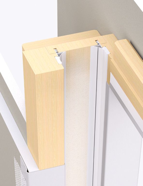
FD30 C   |   D O O R L E A F I N S TA L L AT I O N                                                                                                                                             17

                                                                                                                                      3   ASSEMBLE GEAR

B) Door leaf installation                                                                                                                 3a Screw the bolts into the trolley several
                                                                                                                                          turns and then insert the trolleys into the track.
With the concealed Enigma system the door leaf                                                                              3a
                                                                                                                                          3b Adjust the bolts to achieve a gap
needs to be hung before the trim is fitted.
                                                                                                                                          approximately 20mm between the underside
                                                                                                                                          of the track and the top of the bolt.

                                                     1   FIT HEAD BRACKETS

                                                                                                                            3b
                                                         Fit the head brackets 150mm from the edge of
                                                         the door leaf to centre of the bracket, ensuring
                                                         both brackets are the same way up. Use the
                                                         screws provided.

                                                         IMPORTANT
                                                                                                                                      4   HANG THE DOOR

                                                         1. If you are using the simultaneous opening mechanism                           4a The bracket fits onto the bolt as shown.
                                                           then it needs to be installed now. If using a simultaneous
                                                           opening the door leaf height needs to be reduced by an                         4b Feed the rest of the door at least halfway
                                                           extra 5mm.                                                                     into the pocket and hang the front bracket
                                                                                                                                          onto the trolley bolt.
                                                         2. If you are using a soft close mechanism please refer to
                                                           the soft close instructions to install the door leaf.                          4c With spanners provided, wind the bolts up
                                                                                                                                          or down to plumb the leading edge of the door
                                                         3. If using a self closer then please refer to the self closer
                                                                                                                                          and to achieve the required gap under the
                                                           installation instructions.
                                                                                                                                          door (door undercut).
                                                         4. If using a touch latch, fit the spring plunger into the rear    4a
                                                                                                                                          Tighten the locking nuts to secure the door to
                                                           of the door as per the touch-latch instructions.
                                                                                                                                          the brackets. They may need to be slacked-off
                                                                                                                                          later, to true the door to the trims once they
                                                                                                                                          are fitted.

                                                     2   FIT THE GUIDE CHANNEL

                                                                                                                           4b    4c
                                                         Apply a thin bead of adhesive into the groove in
                                                         the bottom of the door and then tap the plastic
                                                         channel into position.
FD30 C   |   D O O R L E A F I N S TA L L AT I O N                                                                19

                                                     5   FIT THE FRONT THE DOOR STOP

                                                         5a Slide the white nylon door stop into the track
                                                         and fix into place by tightening the grub screw.

                                                         5b This can be finally adjusted once the
                                                         trims are installed.

                                                         IMPORTANT
5a
                                                         If using a soft closer follow the specific soft closer
                                                         instructions.

5b

                                                     6   FIT TRACK END BLOCK

                                                         The track end block fits at the end of the track
                                                         for a single door and in the middle of the two
                                                         tracks for a double door.

                                                         First drill a pilot hole and fix the block into
                                                         place using the Type-9 screw.
FD30 C | C O N C E A L E D T R I M I N S TA L L AT I O N 21
TRIM COMPONENTS
C) Concealed trim installation
Familiarise yourself with components included. All fixings will
come pre-packaged to suit your specific project requirements.
SUPPLIED TOOLS TRIM FIXINGS Concealed Metal Trims Head Trim Strike Trim Pt2
x6 Single door x1 / Double door x2 Single door x2, Double door n/a
Hex Key Spanner Type-5 Strike Trim Pt1 Leading Edge Trim Intumescent Seals
25mm self-drilling screws Single door x1 / Double door n/a Single door x2, Double door x4 15x4mm
TRIM FIXINGS (cont.)
Intumescent Seals Brush Seal Strike Jamb Seals
20x4mm
Type-6 Type-7 Type-8 Type-9
60mm gold screws 35mm self drilling 42mm self drilling 50mm gold screws
drywall screws drywall screwsFD30 C | C O N C E A L E D T R I M I N S TA L L AT I O N 23
1 INSTALL LEADING EDGE TRIM
3 CUT TO LENGTH STRIKE TRIMS
Cut the Leading Edge Trims to the height of Cut Strike Trim Pt1 as per the drawing
the opening and slot them over the flange on measuring from the notch to the end that is not
the leading-edge aluminium jamb, with the notched.
grooves for the brush/intumescent seal facing
in towards the door. Cut Strike Trims Pt2 to the same length.
They must be secured into position with the IMPORTANT
When installing double doors the strike jamb will not be used.
Type-5 screws at 300mm intervals. Please note
that the timber will need to be pilot-holed first.
Strike Trim Pt1
Dimension =
Underside of
head profile
down to floor level
2 LINE THE DOOR UP
If required, the door can now be trued into
alignment with the leading-edge trims by
adjusting the hanger bolts up or down as
necessary.
4
When you’re happy that everything is aligned
INSTALL STRIKE TRIM
and the gaps between the door and trims are
equal, lock the bolts firmly into position by
winding down the locknuts. Fit the notched end of Strike Trim Pt1 centrally
in the head channel and plumb down using a
level. Fix into place using the Type-9 screws.
Fit the Strike Trim Pt2 to either side of Strike
Trim Pt1 and fix into place using the Type-6
screws.FD30 C | C O N C E A L E D T R I M I N S TA L L AT I O N 25
5 SET CLOSER STOP
8 ‘
INSTALL CONCEALED TRIMS
Adjust plastic clip, so the door leaf closes and Cut 4 lengths of the concealed trims to the
is held in place, against the strike jamb. opening height.
IMPORTANT
1. Ensure the frame is square and plumb before fixing.
2. Fix the concealed trim every 200mm.
6 INSTALL HEAD TRIMS
Cut the head trim to the distance between the Fixing the concealed trim
two timber side jambs. Slot into place in the
head using Type-5 screws. Slide over plasterboard and timber frame
and fix into place using Type-7 screws.
Screws should be positioned every 300mm.
IMPORTANT
When installing double doors the strike jamb will
not be used.
7 2ND LAYER OF PLASTERBOARD
9 PLASTERING PREPARATION
Clad the pocket with a second layer of Apply plaster fibre tape to top corners.
plasterboard over the timber frame using
Type-7 screws. IMPORTANT
Before plastering in the trims, using a laser level
ensure that they are straight and true.FD30 C | C O N C E A L E D T R I M I N S TA L L AT I O N 27
10 PLASTER / ARCHITRAVE / PAINT
12 FIT BATWING STRIKE SEALS
Now the wall can be finished. Multi-skim finish Fit the rubber seals to the corners of the
plaster or tape and jointing compound, painted strike trim as shown.
and the architrave fitted.
Please note the architrave is not included within
the Enigma pocket door system.
IMPORTANT
Before plastering in the trims, using a laser level ensure that
they are straight and true.
11 FIT INTUMESCENT SEALS
In order to achieve a FD30 fire rating,
intumescent seals must be fitted as shown.
8a Head
8b Leading edge
11a 8c Closing edge
If you have double doors the meeting stile of
13 ADJUST REMOTE STOP
one door leaf needs the seals fitted as shown Adjust the remote-stop so it holds the door flush
below. These will be specifically labelled in the with the leading-edge trims when the rear trolley
pack you receive. is engaged on the stop.
When correctly aligned, fix the stop into place
with the self-drilling screw provided making sure
that all swarf is wiped/hoovered from the track.
Any debris left in the track will cause the door to
11b
‘rumble’ as it opens and closes.
Congratulations!
You’ve now completed
the installation of your
Enigma doorset.
11cInnovation | Configuration | Strength
Visit our website for the very latest design styles.
Technical support helpline 020 3880 0339
Email sales@enigmapocketdoors.com
K2 Kents Hill Business Park Timbold Drive Milton Keynes MK7 6TTYou can also read