OWNERS MANUAL INSTALLATION & MAINTENANCE INSTRUCTIONS - COMMERCIAL STEEL GARAGE DOORS - Midland Garage Door
←
→
Page content transcription
If your browser does not render page correctly, please read the page content below
Commercial Steel Garage Door - OWNERS MANUAL

          OWNERS MANUAL
                INSTALLATION & MAINTENANCE INSTRUCTIONS

Installed By:
Date:

                                 COMMERCIAL STEEL GARAGE DOORS
                                                                              10-17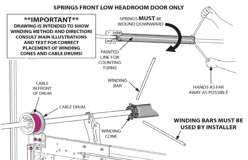
Commercial Steel Garage Door - OWNERS MANUAL

                                            TABLE OF CONTENTS
SAFETY INFORMATION...................................................................................................... Page 2
Before you begin................................................................................................................... Page 3
Tools required........................................................................................................................ Page 3
Hardware components.......................................................................................................... Page 4
Step by step installation instructions..................................................................................... Page 5

SPECIAL APPLICATION INSTRUCTIONS:
   • Standard Radius track instructions.......................................................................... Page 14
   • High Lift track instructions........................................................................................ Page 15
   • Full Vertical Track instructions................................................................................. Page 16
   • Roof Pitch................................................................................................................. Page 16
   • Low Headroom Springs Front/Rear instructions............................................ Page 18 & 26

Maintenance........................................................................................................................ Page 30
Warranty ............................................................................................................................ Page 32

                     IMPORTANT SAFETY INFORMATION
Springs, cables, and bottom fixtures are under extreme spring tension. NEVER ATTEMPT TO REMOVE
FASTENERS ON THESE COMPONENTS UNLESS THE SPRINGS ARE COMPLETELY UNWOUND.

NOTE - All fasteners that are colored in RED are under extreme tension and must never be removed unless
the springs are unwound and all spring tension is released.

CAUTION - Due to the extreme spring tension, never wind or unwind without the proper winding bars. Cold
rolled steel bars 18” to 22” that properly fit the winding cone holes are recommended.

Keep hands and fingers clear of section joints, track, and other door parts when operating the door. The lift
handle, step plate, and pull rope are provided for the safe operation of the door.

CAUTION- ACQ GREEN TREATED LUMBER will corrode zinc and galvanized coated fasteners and
components. Use fasteners appropriate for ACQ lumber. Protect door components as required.

Do not permit children to play underneath or with any garage door operating controls.

Always have the door in view to ensure its travel is free and clear before operating the electric garage door
opener.

Page 2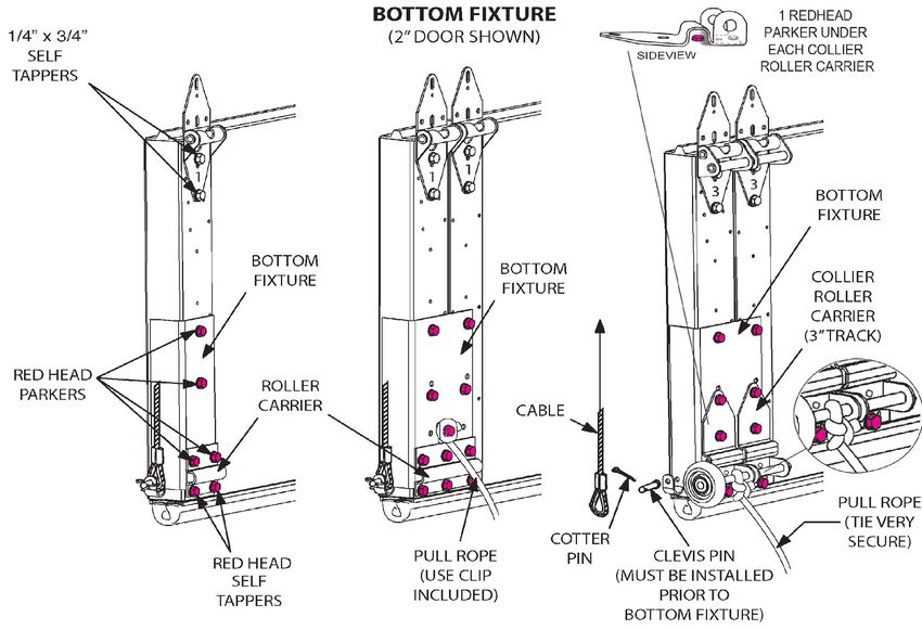
Commercial Steel Garage Door - OWNERS MANUAL

              BEFORE YOU BEGIN: PLEASE READ THIS
•   Take heed of the NOTES and CAUTIONS in this book. They will save you from having to
    redo your work.

•   Study the installation instructions and illustrations before you begin work to understand what
    the various components are and the sequence of assembly.

•   Note that the RED FASTENERS are used on all components that are under spring tension.
    This serves as a WARNING that serious harm could occur if the fastener is removed while
    under spring tension.

•   Verify your type of door and track so you can refer to the proper illustrations and sections of
    this manual.

•   It is recommended to pre drill 1/4” holes for ALL 5/16” x 1 3/4” wood lags...ESPECIALLY
    THE CENTER BEARING PLATE that attaches the spring(s) to the wall. This prevents the
    wood from splitting out and gives the most secure attachment.

•   Remove the PROTECTIVE FILM from the sections upon installation. If the film is allowed to
    get wet the adhesive may transfer from the film to the section.

•   If only one section has a CENTER STILE use it for the top section. It’s for draw bar operator
    attachment.

                                TOOLS REQUIRED
•   HAMMER                        •   DRILL                          •   C-CLAMP
•   SCREWDRIVERS                  •   HACKSAW                        •   LEVEL
•   SOCKET SET,                   •   ELECTRIC IMPACT                •   DRILL BITS:
    3/8” TO 9/16”                     OR SCREW GUN                       1/4”, 5/16”, 3/8”, 7/16”
•   WRENCH SET                    •   SAWHORSES                      •   EXTENSION CORD
•   VISE GRIPS                    •   ROPE                           •   TWO WINDING BARS,
•   TAPE MEASURE                  •   LADDERS,                           18” TO 22”
•   PLIERS                            SCAFFOLD, OR LIFT

                                                                                                    Page 3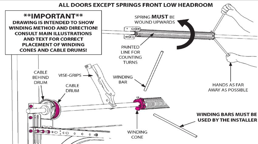
Commercial Steel Garage Door - OWNERS MANUAL
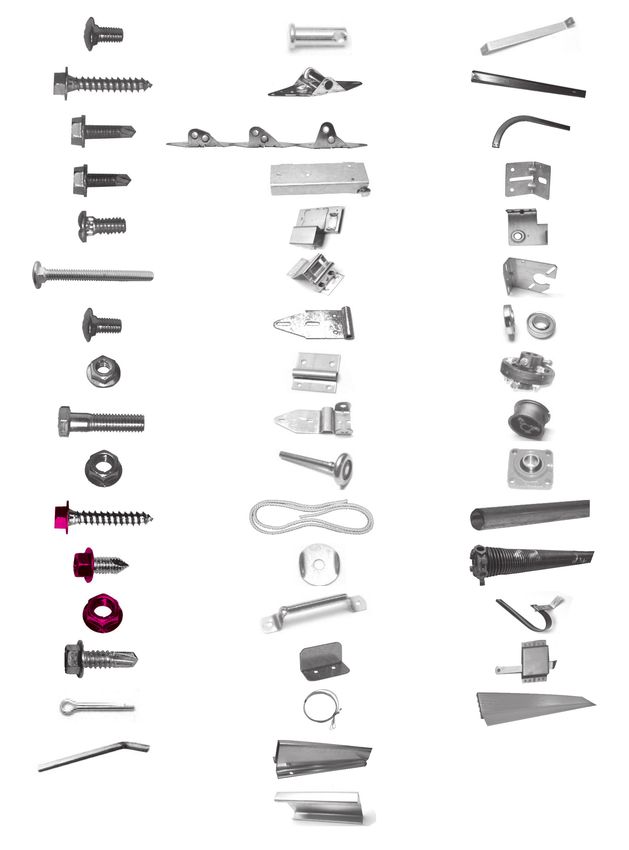
HARDWARE COMPONENTS
3
⁄8 x 7⁄8 Clevis Pin Truss
Carriage Bolt Sag Brace
⁄16 x 13⁄4
5
Hinge #1 Vertical
Wood Lag Track
(1 Pair)
⁄4 x 7⁄8
1
Hinges Horizontal
Self Tapper #2 #3 #4 Track (1 Pair)
⁄4 x 3⁄4
1
Bottom Jamb
Self Tapper Fixture Bracket
⁄4 x 5⁄8
1
Low Head End
Track Bolt Room Bottom Bearing Plate
Fixture
⁄4 Carriage
1
Top Center
Bolt Fixture Bearing Plate
⁄4 x 5⁄8
1
Low Head Bearing
Carriage Bolt Room Top
Fixture
⁄4 Keps Nut
1
Roller Shaft
Carrier Coupler
⁄8 x 11⁄2
3
Collier Cable
Bolt Roller Carrier Drum
⁄8 Flange Nut
3
Roller 4 Hole Pillow
Block Bearing
⁄16 x 13⁄4
5
Rope Spring
Red Head Shaft
Wood Lag
⁄16 x 5⁄8
5
Rope Torsion
Red Head Clip Spring
Parker
3
⁄8 Red Lift Spring
Flange Nut Handle Bumper
⁄16 x 1
5
Step Slide
Self Tapper Plate Lock
Cotter Pin Cable Vinyl
Assembly Weather Strip
⁄4 Square Key
1
Strut
Truss
Page 4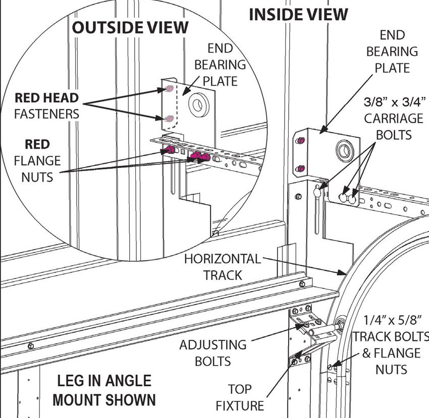
Commercial Steel Garage Door - OWNERS MANUAL

STEP 1:
PREPARE OPENING
Check that the opening is ready. For wood jambs
check that the rough opening equals the door
size. The jamb should be a substantial high quality
2x6 type material. For steel jambs the door will
be 2” wider than the opening. The door will seal
on the vertical track angle mount. Check that you
have the required headroom, side room, and back
room (Fig. 1). The jambs need to be plumb and
the header level to have a square opening. The
vertical jambs and the “header jamb” should be
flush with each other. The inside surfaces of the        Figure 1
jambs where the door will mount should be free of
any protruding objects (nails, bolts, screws) that
may interfere with the door.                                          CAUTION!
                                                        NEVER INSTALL DOOR COMPONENTS
                                                        DIRECTLY ON A SOFT SURFACE LIKE
                                                         SHEETROCK OR BUFFALO BOARD!
STEP 2:
WEATHER STRIP
WOOD JAMBS: Tack the Vinyl Door Stop in place
with the flat edge placed 1/8” from the inside edge
of the door jambs and header (Fig 2). Six or seven
penny galvanized nails work well.

NOTE:
• IF YOU WILL BE USING ANGLE MOUNT
WEATHER STRIP OR ALUMINUM VINYL
PERIMETER SEAL FOR STEEL JAMBS, THESE
WILL BE APPLIED LATER.

• DOOR STOP IS AN OPTION WHICH MUST
BE ORDERED IN ADDITION TO THE DOOR
PACKAGE.
                                                         Figure 2

STEP 3:
ORGANIZE
Set your sawhorses up in a clear convenient area.     Organize it into groups so you can easily find the
Be sure there is nothing on the sawhorses that will   parts as you go. Organize the fasteners in the
dent or mar the paint of the sections. Spread the     hardware box in the same manner.
hardware out on the floor near the sawhorses.

                                                                                                    Page 5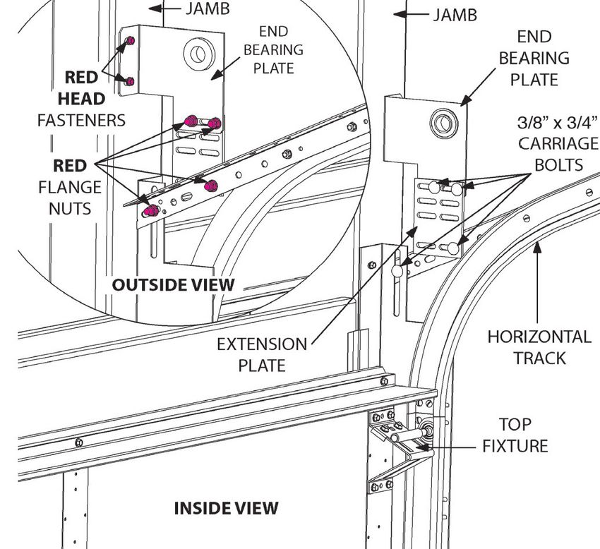
Commercial Steel Garage Door - OWNERS MANUAL

   Figure 3

STEP 4:                                                  roller carrier. Place the bottom fixture roller carriers
BOTTOM SECTION                                           in position and fasten with 5/16” x 5/8” RED HEAD
ATTACHING PARTS:                                         parkers in the upper holes. Use RED HEAD self
Lay bottom section across sawhorses.                     tappers in the lower holes (Fig. 3).

NOTE: FOR LOW HEADROOM APPLICATIONS                      END HINGES: Refer to (Fig. 4) to determine the
REFER TO PAGE 26. FOR ALL OTHER                          proper number hinge to start with. Position the
APPLICATIONS USE THE FOLLOWING                           hinge over the pre-punched holes on the end stile
INSTRUCTIONS.                                            at the top of the section. Orient hinges as shown in
                                                         (Fig. 5). Fasten hinges with 1/4” x 3/4” self tappers.
BOTTOM FIXTURES: (Fig. 3). If the left and
right bottom fixtures are attached together, bend        INTERMEDIATE HINGES: Position a #1 hinge over
them back and forth at the joining tabs until they       the pre-punched holes at the top of the section on
separate. Attach cable to right and left hand bottom     each intermediate stile. ThermoGuard models use
fixtures with 1/4” clevis pin and cotter key. Position   Tog-L-Lock marks to determine hinge position.
bottom fixtures along bottom edge of end stiles          (SEE FIGURE 5 FOR PROPER ORIENTATION
and fasten with 5/16” x 5/8” RED HEAD parkers,           OF HINGES.) Fasten hinges with 1/4” x 3/4” self
leaving the bottom holes open for installation of        tappers.

Page 6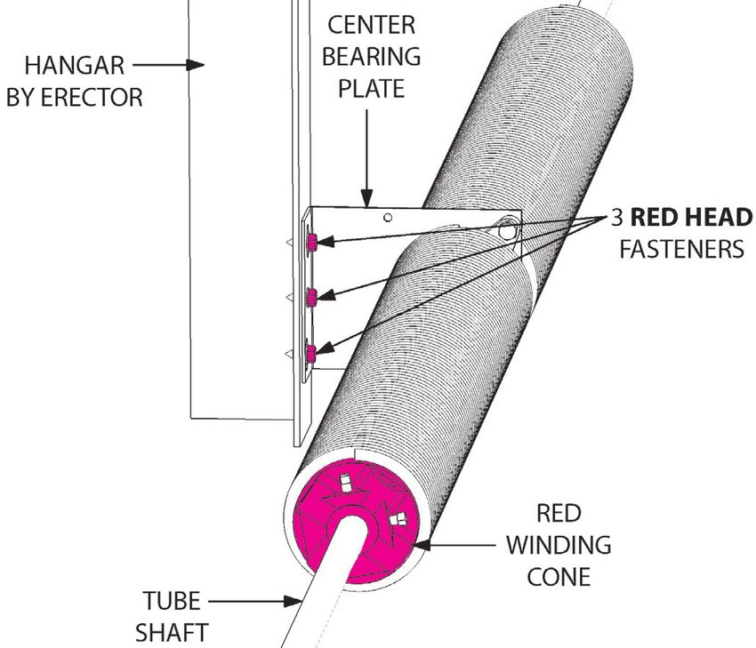
Commercial Steel Garage Door - OWNERS MANUAL

STEP 5:
BOTTOM SECTION
STEP PLATE:

Follow the appropriate
instructions below depending
on your type of lock:
                                      Figure 5

KEYED LOCK- Two step plates are provided in
the hardware box. One is for the inside and one for
the outside of the door. The carriage bolts and tube
spacers are located in the keyed lock package. The
step plates should be attached to the stile directly
under the lock and positioned at the bottom edge of
the bottom section.                                          Figure 4

Using the step plate as a template, drill two 7/16”       the outside of the door. Insert the spacers. Fasten
holes using care to drill straight and true. The other    step plates to inside and outside of section using the
end of the hole you drill will locate the step plate on   two 1/4” carriage bolts and kep nuts provided.

   Figure 6
                                                                                                          Page 7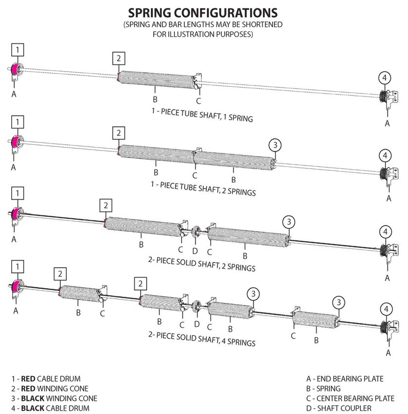
Commercial Steel Garage Door - OWNERS MANUAL

CAUTION:
DO NOT OVERTIGHTEN BOLTS                            STRUT LOCATION ON THE SECTIONS
ON STEP PLATE                                       On BOTTOM and INTERMEDIATE SECTIONS:
                                                    For all C2ES,
INSIDE SLIDE LOCK- You received one step            C3ES, Ribbed, and
plate for the inside of your door. Location of      ThermoGuard models,        THERMO
                                                                                GUARD
the step plate varies according to preference.      place the struts and       MODELS

Generally it is put on the end of the door          trusses in center of the
nearest the walk-in access, either on the first     section (For window
stile in from the end of the door or on the         sections, place strut
bottom fixture directly above bottom roller.        above the window and
Attach using 1/4” x 7/8” self tappers (Fig. 6).     below the hinges) (Fig.
                                                    7a).
STEP 6:                                                                           Figure 7a
PULL ROPE                                           For all Thermal Steel
Install pull rope only if door will be hand
                                                    models (Fig. 7), strut                    THERMO

operated. DO NOT INSTALL THE PULL                                                              STEEL

                                                    attachment points must                    MODELS

ROPE IF THE DOOR WILL BE OPERATED
                                                    be in the area of the
BY AN ELECTRIC OPENER. Tie a knot in
                                                    hidden hinge plates.
each end of rope. Drill a 1/4” hole in the bottom
fixture as close to the bottom roller as possible
                                                    On TOP SECTIONS:
making sure to leave room for the rope clip.
                                                    For all door models,
Fasten rope to bottom fixture using rope clip
                                                    place the strut at the
and 5/16” x 5/8” RED HEAD parker (Fig. 3).
                                                    very top of the section,
Let opposite end of rope hang loose.
                                                    above the top fixtures.       Figure 7
                                                    The exception to this
STEP 7:                                             would be a door with LHR track (Fig. 45). If a truss is
STRUTS                                              required, place the truss in center of the section, below
Use the charts on the next page to determine
                                                    where the operator arm would attach.
what sections to put the struts and trusses on
for your door. These charts give the typical
                                                    INSTALL THE STRUT: To install a strut on a section,
locations for 2” Steel Doors and the 3” Energy
                                                    place the section on saw horses and place the strut in
Saver doors.
                                                    position on the section. Adjust the sawhorses in or out
                                                    so the section sags 1/2” or so under the strut (Fig. 8
NOTE: IF YOU HAVE A CU 175 REFER TO
                                                    & 9). First, fasten strut to end stiles on both ends with
THE SEPARATE INSTRUCTION SHEET FOR
                                                    1/4” x 7/8” self tappers. Then fasten strut to center stile
STRUT ATTACHMENT.
                                                    with 1/4” x 7/8” self tappers. Finally, fasten strut to any
                                                    remaining intermediate stiles.
GENERAL GUIDELINES:
Top sections need the most support. If you
                                                    NOTE: PREPUNCHED HOLES IN STRUTS DO NOT
have a combination of trusses and struts a
                                                    ALWAYS ALIGN WITH THE STILES.
truss will always go on the top section. If you
have a combination of 3” and 2” struts the 3”
strut will always go on the top section. If there
is only one strut for the door locate it on the
top section.
Page 8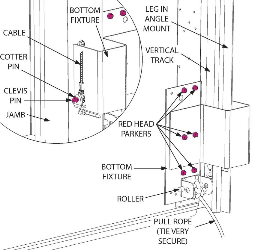
Commercial Steel Garage Door - OWNERS MANUAL
TYPICAL TRUSS / STRUT LOCATIONS ON 2” STEEL DOORS
TYPICAL TRUSS/STRUT LOCATIONS ON 2” THERMOGUARD DOORS
Typical Truss/Strut locations on 2" Thermoguard Doors
S
S S
S S S
S S S S
S S S S
S S
S
S S S S S S S S S S S
12' 14' 16' 18' 10' 12' 14' 16' 18' 8' 10' 12' 14' 16' 18' 20'
12' wide 14' wide 16' wide
Typical Truss/Strut locations on 2" Thermoguard Doors
TYPICAL TRUSS / STRUT LOCATIONS ON A WHITE 3” ENERGY SAVER
Typical Truss/Strut locations on 3" White Thermoguard Doors
S
T T
T S3
S T S3
S S
T S3S S3 T TS T S
T S3 S3 T T S S3 S3
S3 S S
T S3 S3 T S3 T ST T T T S
T S3 S3 S3 S3 S3 S3 S3 S3 S3 S3
S
S3 S3 S3 T S3 S3 T T T T T
S3 T T S3 T T S3 S3 S3 S3 S3
T S3 S3 S3 S3 S3 S T T TS TS T S S S S S S
S3 S3 S3 S3 S3 S3 S3 S3 S3 S3 S3
10' 12' 14' 16' 18' 20' 12' 14' 16' 18' 20'
12' 14' 16' 18' 10' 12' 14' 16' 18' 8' 10' 12' 14' 16'
22' wide 24', 26' wide
12' wide 14' wide 16' wide
Typical Truss/Strut locations on 3" White Thermoguard Doors
TYPICAL TRUSS/STRUT LOCATIONS ON 3” WHITE THERMOGUARD DOORS
T T
T S3 T S3
T S3 S3 T T T
T S3 S3 T T S3 S3 S3
T S3 S3 T S3 T T T T T
T S3 S3 S3 S3 S3 S3 S3 S3 S3 S3
S3 S3 S3 T S3 S3 T T T T T
S3 T T S3 T T S3 S3 S3 S3 S3
T S3 S3 S3 S3 S3 T T T T T
S3 S3 S3 S3 S3 S3 S3 S3 S3 S3 S3
10' 12' 14' 16' 18' 20' 12' 14' 16' 18' 20'
22' wide 24', 26' wide
Page 9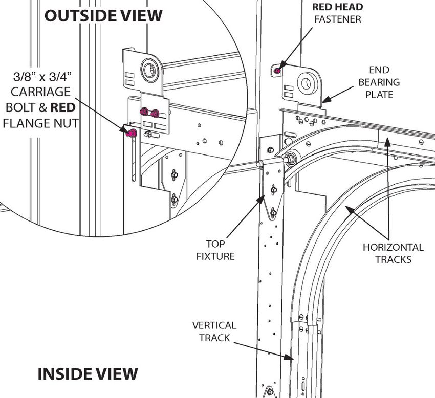
Commercial Steel Garage Door - OWNERS MANUAL

                      STEP 8:
                      BOTTOM SECTION
                      REMOVE THE PROTECTIVE FILM FROM
                      THE OUTSIDE FACE OF THE SECTION. To
                      aid removal use a knife to LIGHTLY scribe a
                      line where the film runs under the end stiles
                      and the aluminum bottom astragal retainer.

                      Install the hinges, rollers, and bottom fixtures (Fig
                      10).

                      NOTE: IF YOU HAVE TWO ROLLERS THAT
                      ARE LONGER THAN ALL THE REST THEY
                      WILL GO IN THE BOTTOM FIXTURES.
   Figure 8

                      STEP 9:
                      INSTALL THE BOTTOM SECTION
                      AND VERTICAL TRACK
                      Determine your type of track and jamb and follow
                      the appropriate instructions below:

                      PREP THE ANGLE MOUNT VERTICALS: Loosen
                      the 1/4” track bolts that fasten the track to the
                      angle mount (or jamb brackets) so the track can
                      be adjusted in and out. If using ANGLE MOUNT
                      WEATHERSTRIP, clip it on the 3” leg of the angle
                      mount at this time (Fig. 11).

   Figure 9

   Figure 10              Figure 11
Page 10
Commercial Steel Garage Door - OWNERS MANUAL
PREP THE JAMB BRACKET MOUNT
VERTICALS: Assemble the jamb brackets to the
vertical tracks, matching the lowest numbered
jamb bracket with lowest ADJUSTABLE SLOT.
Match the remaining jamb brackets in ascending
order with additional ADJUSTABLE SLOTS (Fig.
12). Attach the jamb brackets to vertical tracks
with 1/4” x 5/8” carriage bolts and 1/4” kep nuts.
FINGER TIGHTEN ONLY.
ALL DOORS:
Position the bottom section inside the opening
against the jambs. The bottom section must
be leveled by temporarily shimming up the low
side. Use a 2’ or 4’ level. Center the section in the
opening (Fig. 13). Figure 12
Hook vertical track over the rollers on the end of
the bottom section and swing it into place against
the jamb (Fig. 14). Position bottom of track 1/2”
or so above floor (It works well to set the track on
a block of wood to hold it at the proper height.).
Raising the tracks allows adjustment in and out
and will reduce corrosion. Position vertical track so
that the tops of both sides are level with the other.
Since the bottom section is level, you may level
the top of the vertical track by measuring from the
top of the vertical track to the top of the bottom
section and setting both vertical tracks at the same
distance.
Also, the two vertical tracks will be installed in
a “wedge” shape compared to the door. For 2”
Figure 13
TRACK, space the bottoms of the tracks 3/8” from
the door and space the tops of the tracks 5/8” from
the door.
Figure 14
Page 11Commercial Steel Garage Door - OWNERS MANUAL
This has the effect of centering the door every time
it goes up and down. If you are using 3” TRACK
this spacing should be 1/2” and 7/8” respectively
(Fig. 15).
Fasten the angle mount (or jamb brackets) to the
jamb with the appropriate fasteners. For STEEL
JAMBS use 5/16” X 1” self tappers (Fig. 11). For
WOOD JAMBS (Fig. 14 shows a final assembly),
make a 1/4” pilot hole and use 5/16” x 1 3/4” wood
lags.
NOTE: Enough fasteners are provided
to anchor the angle mount to the jamb
approximately every 2’. Start at the lower most
hole and work up from there. There may be
holes that are unused.
STEP 10: Figure 15
SECTION PLACEMENT
If your new door has a combination of 18” and 21” NOTE: LEAVE THE HINGE / ROLLER OFF
or 21” and 24” sections, you must decide which THE RIGHT SIDE. THEY WILL BE INSTALLED
sections will be placed where in the door. If your AFTER THE SECTION IS STACKED IN THE
door has only one larger section, the factory will OPENING.
make it into a bottom section. If there are two
larger sections, one will be the bottom and the Install the strut as required. If a keyed lock is
other should be the top. After this, as a general utilized install it in the second section using the
rule ,place the larger sections toward the bottom instructions in the commercial keyed lock package.
and the smaller sections toward the top.
STEP 12:
NOTE: If there is a “TOP SECTION” with a STACK SECOND SECTION
center stile (for a drawbar operator), ensure Stack the second section in the opening. Hook the
that it is used at the top of the door. roller on the left side of the section into the track
and swing the section into the opening (Fig. 16).
STEP 11: Install the right hand hinge/roller assembly.
SECOND SECTION PREP
Remove the film from the section. Position the NOTE: If desired you can leave all the end
proper hinges at the top of the section in the same hinges off, stack the section in the opening
manner as with the bottom section. Use the next and then install both sets of end hinges with
size larger hinges on the end stiles and #1 hinges rollers.
on the intermediate stiles as required (Fig. 4).
Fasten hinges with 1/4” x 3/4” self tappers. Fig. 17 shows a method of clamping the section
in place with a vise grip until the end hinges are
installed. Fasten hinges from the bottom section
to the second section using the 1/4” x 3/4” self
tappers.
Page 12Commercial Steel Garage Door - OWNERS MANUAL
Figure 16 Figure 17
STEP 13:
REMAINING SECTIONS
Add appropriate hardware and install the remaining
sections. If there is a window section ensure
it will go in the proper place. REMOVE THE
PROTECTIVE FILM FROM ALL SECTIONS
STEP 14:
TOP SECTION PREP
FOR LOW HEADROOM APPLICATIONS REFER
TO PAGES 26-29
If a strut is required, place the strut at the very top
of the section and fasten according to instructions
in step 7 (Fig. 18). Position the top fixture directly
below the strut with the adjusting bolts facing up.
Attach to the section with 1/4” x 7/8” self tappers.
Loosen the two 5/16” nuts on each top fixture Figure 18
so that the roller carrier can slide in and out for
later adjustment. IF YOUR DOOR HAS NO TOP
STRUT, PLACE THE TOP FIXTURES 2 1/2” NOTE: IF AN ELECTRIC DRAWBAR OPENER
BELOW THE TOP OF THE SECTION. IS TO BE ATTACHED TO THIS DOOR, THE
TOP SECTION MUST BE REINFORCED WITH A
STACKING THE TOP SECTION: You can either: STRUT AND THE OPERATOR ARM MUST BE
1) Stack the top section now and hold it in place ATTACHED SO THAT IT IS APPROXIMATELY
with nails, clamps, C clamps, or vise grips, as IN LINE WITH THE TOP ROLLERS. IF THESE
required or 2) Wait to stack the top section until the INSTRUCTIONS ARE NOT FOLLOWED THE
horizontal tracks are installed. WARRANTY WILL BE INVALID.
Page 13Commercial Steel Garage Door - OWNERS MANUAL STEP 15: SET VERTICAL TRACK Snug the top of the vertical track toward the jamb against the highest roller. Tighten the track bolts in the flag bracket/angle mount to hold it in position. This enables you to properly locate the horizontal track for the next step. Do not tighten the other track bolts on the vertical at this time. That will be done later. STEP 16: INSTALL TOP TRACKS It is now time to install the top tracks. Turn to the appropriate section for your application within step 16 and follow the instructions there. STANDARD RADIUS (Fig. 6 shows a typical installation.) Figure 19 HORIZONTAL TRACK: Suspend the rear of the horizontal track assembly from the ceiling with rope (Fig. 19). Position the front of the horizontal track on top of the vertical track and attach using the 1/4” x 5/8” track bolts and 1/4 keps nuts and the 3/8” x 3/4” carriage bolt and RED flange nut (Fig. 20). Only finger tighten the bolts at this time. Check that the horizontal track is level or slightly up. With the horizontal and vertical tracks properly aligned (so the rollers will roll through the joint smoothly), tighten the bolts to secure the horizontal track in place. TOP FIXTURE: Slide adjustable bracket on top fixtures (Fig. 20) away from door until the top section is tight against the door-stop and tighten the adjusting bolts. Figure 20 END BEARING PLATE: Attach the End Bearing Plates as shown in (Fig. 20). Use the 3/8” x 3/4” carriage bolts and RED flange nuts and RED HEAD parkers or RED HEAD wood lags as required. Now go to step 17. Page 14
Commercial Steel Garage Door - OWNERS MANUAL

    Figure 21

HIGH LIFT
(Fig. 21 shows typical installation.)                      Ensure there is a good fit between all the track
HORIZONTAL TRACK:                                          joints so the rollers can pass smoothly.
Locate the left hand “HIGH LIFT VERTICAL
TRACK”. Attach it to the top of the verticals with         TOP FIXTURE: Slide adjustable bracket on top
two 1/4” x 5/8” track bolts and 1/4” keps nuts (Fig.       fixtures (Fig. 22) away from door until the top
22). Attach the left hand HORIZONTAL TRACK                 section is tight against the door stop and tighten the
with the head plate to the top of the high lift vertical   adjusting bolts.
track just installed, with two 1/4” x 5/8” track bolts
and 1/4” keps nuts. Use a level to plumb it in place       The back hang and spring bumpers will be installed
so the HIGH LIFT VERTICAL TRACK is exactly                 later. Now go to step 17.
vertical. Secure the head plate to the jamb with
appropriate RED HEAD fasteners (Fig. 23).

Use a temporary rope if/as required to support the
rear of the horizontal tracks during this process.

Install the right hand track in the same manner.
Instead of using a level to plumb the right hand
track, measure the distance between the vertical
tracks at the top of the door. Then locate the right
hand head plate to achieve the same distance
between the upper tracks. Fig. 24 shows how
to measure this as “Distance 1” and “Distance
2”. Anchor the right hand head plate with the
appropriate RED HEAD fasteners.
                                                              Figure 22
                                                                                                          Page 15
Commercial Steel Garage Door - OWNERS MANUAL
Figure 23
FULL VERTICAL Figure 24
(Fig. 24 shows a typical installation.)
Attach the left hand UPPER VERTICAL LIFT
TRACK to the top of the verticals with two 1/4” x
5/8” track bolts and 1/4” keps nuts (Fig. 22). Use a
level to plumb it in place so the Upper Vertical Lift
Track is exactly vertical. Secure the head plate to
the jamb with appropriate RED HEAD fasteners
(Fig. 25).
Install the right hand upper vertical lift track in the
same manner. Instead of using a level to plumb the
right hand track, measure the distance between the
vertical tracks at the top of the door. Then locate
the right hand head plate to achieve the same
distance between the upper tracks. This is shown
as Distance 1 and Distance 2 on Fig. 24. Anchor
the right hand head plate with the appropriate RED Figure 25
HEAD fasteners.
The SPRING BUMPERS and SWAY BRACES will
Ensure there is a good fit between the lower be installed later. Now go to step 17.
and upper verticals so that the rollers can pass
smoothly through the joints. ROOF PITCH
(Fig. 26 shows typical installation.)
TOP FIXTURE: Slide adjustable bracket on top HORIZONTAL TRACK: The horizontal track will
fixtures (Fig. 22) away from door, until the top follow the incline of the roof. Suspend the rear of
section is tight against the door-stop, and tighten the horizontal track assembly from the ceiling with
the adjusting bolts. rope (Fig. 19).
Page 16Commercial Steel Garage Door - OWNERS MANUAL
Figure 26
Position the front of the horizontal track on top of Use the 3/8” x 3/4” carriage bolts and RED flange
the vertical track and attach using the 1/4” x 5/8” nuts and RED HEAD Parkers or RED HEAD
track bolts and flange nuts and the 3/8” x 3/4” wood lags as required to anchor the bearing plates
carriage bolt and RED flange nut. Only finger in position.
tighten the bolts at this time. Ensure the rear of the
tracks are at or slightly above their final position. Now go to step 17.
Ensure the horizontal tracks line up properly over
the vertical tracks (so the rollers will roll through
the joint smoothly). Tighten the bolts to secure the
horizontal track in place.
NOTE: The factory has cut all angles based on
the pitch specified. Actual field conditions may
vary and require small modifications to the joint
between the vertical and horizontal tracks.
TOP FIXTURE: Slide adjustable bracket on top
fixtures (Fig. 27 ) away from door until the top
section is tight against the door-stop and tighten
the adjusting bolts.
END BEARING PLATE: Attach the End Bearing
Plates (Fig. 27). The EXTENSION PLATE is used
to raise the shaft line high enough so the top
section will clear the drum. As a general rule the
steeper the incline on the track, the higher you
Figure 27
need to raise the end bearing plate.
Page 17Commercial Steel Garage Door - OWNERS MANUAL
LOW HEADROOM FRONT/REAR:
Installation is the same as “Standard Radius”
except the End Bearing Plates are factory installed
on the horizontal track. Install the top section if not
done previously. Install the LHR top fixtures. Put
1/4” x 7/8” self tappers in the slots only, so they can
be adjusted to final position later (Fig. 28).
STEP 17:
INSTALL CENTER BEARING PLATE(S)
Refer to the Spring Assemblies Illustration (Fig.
29) and determine which spring/shaft configuration
your door uses. Arrange the Center Bearing
Plate(s) along the shaft line so there is enough
room for each spring.
REMEMBER- A SPRING MAY STRETCH A
COUPLE INCHES AS IT IS WOUND! Figure 28
NOTE: For CENTER PULL and COUPLED DUAL
SHAFT LINE doors refer to the instruction
insert located in the hardware box.
The Center Bearing Plate(s) must be in line with
End Bearing Plates so the shaft line is straight.
This may be accomplished by measuring from the
top of the door to the center of the shaft line at
the End Bearing Plates. Use that measurement to
locate the Center Bearing Plate above the door.
Figure 30 shows a typical installation.
FOR WOOD HEADER: Attach Center Bearing
Plate(s) to the header using three 5/16” x 1 3/4”
RED HEAD wood lags. Pre-drill holes with 1/4” bit
to prevent wood from splitting.
FOR STEEL HEADER: Fasten with three 5/16”
x 5/8” RED HEAD parkers per Center Bearing
Figure 29
Plate. Pre drill a 1/4” pilot hole as required.
-CAUTION -
The Center Bearing Plate(s) anchors the
springs and must be fastened securely to the
wall. NEVER MOUNT ON A SOFT SURFACE
SUCH AS SHEET ROCK. NEVER ATTEMPT TO
REMOVE THE CENTER BEARING PLATE IF
THE SPRINGS ARE WOUND.
Page 18Commercial Steel Garage Door - OWNERS MANUAL
Figure 30
STEP 18: the LEFT side of the door and the spring with the
SPRING SHAFT ASSEMBLY BLACK winding cone is to the RIGHT side of the
door. Slide the cable drums on the shaft. The RED
NOTE: FOR LOW HEADROOM APPLICATIONS drum goes and the LEFT side and the BLACK
REFER TO PAGE 26. FOR ALL OTHER drum on the RIGHT side. Ensure the set screws are
APPLICATIONS, USE THE FOLLOWING facing “IN” toward the center of the door.
INSTRUCTIONS.
SHAFT COUPLER: If your door utilizes a split solid
Refer to the Spring Assemblies Illustration (Fig. 29) shaft, install the SHAFT COUPLER by removing
and determine which spring/shaft configuration your the 3/8” x 2” joining bolts and installing a coupler
door uses. Assemble the components accordingly. half on each of the shafts. Insert the square
Place the spring shaft on saw horses. Insert a keyways and tighten the setscrews and lock nuts
BEARING into one spring anchor cone (Fig. 31a) (Figs. 31a & 32). Save the joining bolts for after the
and slide the spring(s) on the shaft(s) (It is easier to springs are wound.
work with heavier spring assemblies on the floor.).
NOTE: If a JACKSHAFT OPERATOR is going to
NOTE: FOR TUBE SHAFT, ONLY ONE CENTER be used, one shaft will be longer than the other.
BEARING IS REQUIRED WHETHER THE DOOR USE THE LONGER SHAFT ON THE SIDE THE
IS SUPPLIED WITH ONE SPRING OR TWO. JACKSHAFT OPERATOR WILL BE INSTALLED.
FOR SOLID SHAFT, EACH SPRING WILL GET A
BEARING. NOTE: If your door utilizes “PILLOW BLOCK
BEARINGS” on your End Bearing Plates, you
CAUTION: The springs are LEFT and RIGHT hand must use a SPACER between the drum and the
wound. WHEN INSIDE THE BUILDING LOOKING End Bearing Plate (Fig. 33).
OUT the spring with the RED winding cone is on
Page 19Commercial Steel Garage Door - OWNERS MANUAL
Figure 31 (a&b)
Figure 32 Figure 33
STEP 19: the spring set screws on the Shaft to prevent the
INSTALL SPRING ASSEMBLY springs from moving during this process.).
Use the appropriate instruction below:
TUBE SHAFT: Lift the spring assembly up into SPRINGS WITH RED CONES MUST BE FACING
position. Slide the left end of Shaft through the left THE LEFT SIDE OF THE DOOR AND SPRINGS
End Bearing Plate and slide back through right End WITH BLACK CONES MUST BE FACING THE
Bearing Plate (It may be helpful to slightly tighten RIGHT SIDE OF THE DOOR.
Page 20Commercial Steel Garage Door - OWNERS MANUAL
Figure 34 Figure 35
Fasten to Center Bearing Plate with 3/8” x 1 1/2” Use the appropriate instruction below:
bolts and the RED 3/8” flange nuts and tighten (Fig.
34). Be sure the shaft line is straight both up and NOTE: On FULL VERTICAL and HIGH LIFT you
down and in and out from the wall. will have “extra” cable length. Do not cut the
cables. Wrap the extra cable on the drum.
SOLID SHAFT: Lift the left spring assembly up
into position and slide the shaft through the End TUBE SHAFT: Position the left (RED) cable drum
Bearing Plate. Fasten the anchor cones to Center tightly against the left End Bearing Plate and tighten
Bearing Plate with 3/8” x 1 1/2” bolts and the RED the set screws. Bring cable up between wall and
3/8” flange nuts and tighten (Fig. 31). Be sure the roller stem, behind the cable drum and position the
shaft line is straight both up and down and in and cable bead into the notch on the outside edge of
out from the wall. Repeat process for the right cable drum (Fig. 35). ROTATE THE CABLE DRUM
spring assembly. Butt the left and right shaft coupler AND THE SHAFT UNTIL CABLE IS TIGHT. Check
halves against each other, but do not install the 3/8” to be certain there is no “loose” cable on the drum
x 2” joining bolts yet. and that the cable runs free and clear all the way
to the bottom fixture. Clamp a vise grip on top of
NOTE: THE SPRING ANCHOR CONES MUST FIT the shaft and against the header to maintain cable
SNUGLY AND EVENLY AGAINST THE CENTER tension (Fig. 36). Take note of the cable tension you
BEARING PLATE. have. You will want to duplicate that tension on the
right side.
STEP 20:
SET THE CABLE DRUMS NOTE: DO NOT SEVERELY OVERTIGHTEN SET
Center the shaft line so there is an equal amount SCREWS ON DRUMS OR SPRINGS. This would
extending through the left and right End Bearing distort and weaken the shaft.
Plates.
Position the right (BLACK) cable drum tightly
NOTE: If your application will have a Jackshaft against the right End Bearing Plate and bring cable
Operator, you will have solid shafts. One of the up as before and fasten to cable drum. Rotate the
shafts will be 12” longer for the operator to cable drum until this cable has the same tension as
hook up to. the left cable. Tighten the set screws in sequence
(Fig. 37).
Page 21Commercial Steel Garage Door - OWNERS MANUAL
Figure 36
NOTE: CABLE TENSION ON EACH SIDE
MUST BE EQUAL SO THE DOOR WILL BE
LEVEL AND OPERATE PROPERLY.
SOLID SHAFT: Make sure the left and right shaft
couplers are butted up against each other. Starting
on the left side, slide the cable drum against the
End Bearing Plate. Insert the Square Key in the
keyway and tighten the setscrews (Fig. 31b).
Bring cable up between wall and roller stem,
behind the cable drum, and position the cable
bead into the notch on the outside edge of cable
drum (Fig. 35). ROTATE THE CABLE DRUM AND
THE SHAFT UNTIL CABLE IS TIGHT. Check to
be certain the cable bead is seated against the
cable drum and that there is no “loose” cable on
Figure 37
the drum. The cable must run free and clear all
the way down to the bottom fixture. Clamp a vise
grip on top of the shaft and against the header
to maintain cable tension (Fig. 36). Repeat this
process on the right side.
Page 22Commercial Steel Garage Door - OWNERS MANUAL
STEP 21: AS A DOUBLE CHECK: ALWAYS WIND IN THE
WINDING SPRINGS DIRECTION INDICATED BY THE CUT OFF END
Clamp the door down. OF THE SPRING WIRE (Fig. 38).
- CAUTION - Wind springs carefully, keeping hands as far away
CLAMP DOOR SECURELY CLOSED ON BOTH from springs as possible for best leverage (Fig.
SIDES USING C-CLAMP VISE GRIPS BEFORE 36). The spring will stretch as you wind it. Upon
WINDING ANY TENSION ONTO SPRINGS. completing the number of turns specified, be sure
SPRING TENSION IS DANGEROUS. ONLY USE the spring has stretched enough and is not “bound
PROPER SIZED WINDING BARS. NEVER USE up”. Tighten set screws on spring winding cone
SCREWDRIVERS OR OTHER TOOLS TO WIND while maintaining spring tension (If you have a
SPRINGS. SOLID SHAFT, one of the set screws is typically
run in the 1/4” keyway of the shaft.). After winding
COMMERCIAL DOOR SPRINGS CAN BE all springs, go to Step 22.
LARGE AND POWERFUL. MAKE SURE
LADDERS, SCAFFOLDING OR LIFTS ARE LEAVE THE WARNING TAG ATTACHED
SECURE AND STABLE AND PROVIDE A TO THE SPRING!
GOOD POSITION FROM WHICH TO WIND THE
SPRINGS. IF YOU MUST REDUCE SPRING TENSION OR
UNWIND COMPLETELY: Follow all precautions
Make a line across the spring(s) to assist in for winding springs. If there is only one spring on
counting turns as you wind the spring. A grease the door, clamp a vise grip on the spring shaft to
pencil, chalk, or spray paint works well (Fig. 36). hold the cable drums in place (Step 20). Insert
winding bar in the spring cone and hold tension
Using two cold rolled steel winding bars that fit against the spring. Carefully loosen the set screws
snugly in the holes of the winding cone, wind and hold the full spring tension. Unwind the spring
springs the number of turns (COMPLETE the desired amount. Reset set screws as required.
REVOLUTIONS) specified on the spring tag. The
bars should be at least 18” long. The bigger the
springs, the longer the bar should be.
Figure 38
Page 23Commercial Steel Garage Door - OWNERS MANUAL
STEP 22: STANDARD RADIUS, ROOF PITCH, & LOW
SHAFT COUPLER: HEAD ROOM: Install 3/8” x 1 1/2” bolts at the rear
(SOLID SHAFT ONLY) Install and tighten the three end of the horizontal tracks. These prevent the top
3/8” x 2” joining bolts (Fig. 32). section rollers from rolling out the back of the track.
STEP 23: FULL VERTICAL: Install a SWAY BRACE on each
BACK HANG: ALL DOORS EXCEPT upper vertical track to prevent them from spreading.
FULL VERTICAL Raise the door to its desired full open position,
Use the following to determine your doors back clamp in place, and install the SPRING BUMPERS
hang requirements: (Fig. 25).
STANDARD RADIUS OR LOW HEAD ROOM: HIGH LIFT: Raise the door to its desired full open
• Doors up to 8’ high - One back hang per side. position, clamp in place, and install the SPRING
• Doors over 8’ high and up to 14’ high - Two BUMPERS (Fig. 21).
back hangs per side.
• Doors over 20’ wide OR over 14’ high - Three LOW HEAD ROOM:
back hangs per side. TOP FIXTURES: With the door fully closed, final
adjust the top fixtures so the top section fully
HI LIFT: closes. Add an additional self tapper in each so
• Back of horizontals up to 8’ from header - One the top fixtures can’t move. If a strut is required
back hang per side. at the top of the section (for doors with a drawbar
• Back of horizontals 8’ to 16’ from header - Two operator), install the strut over the top of the top
back hangs per side. fixtures (Fig. 28).
• All Doors over 20’ wide - One back hang per
side for every 6’ horizontal track. ALL DOORS:
Attach the LIFT HANDLE and the INSIDE SLIDE
Remove the vise grip(s) from the shaft line. While LOCK to the second section with self tappers
keeping a good hold on the door (in case the (Fig. 6). The door should work smoothly and easily
springs are overwound), remove the clamps holding throughout its range of operation. Adjust spring
the door down. Raise the door approximately half tension in 1/4” turn increments as required. Ideally,
way up or to the first back hang position and clamp the door should be able to rest on the floor, stop
in place. Ensure that the tracks are level or slightly half way up, and pull down reasonably well, out of
up and run parallel with the door with approximately the opening.
1/2” clearance between the track and the door.
Back hang the door (See your door types main With door closed, push the lower portion of vertical
illustration for back hang examples.). track towards jamb until door fits lightly against door
stop and tighten the 1/4” kep nuts on jamb brackets/
NOTE: PUNCHED ANGLE IS AN OPTION FOR angle mount.
BACK HANG WHICH MUST BE ORDERED IN
ADDITION TO THE DOOR PACKAGE. Ensure that the rollers run smoothly through the
joint of the vertical and horizontal tracks. Use your
STEP 24: hammer or vise grips to make small adjustments if
FINAL ITEMS AND ADJUSTMENTS they are not lined up well.
Choose the final instructions for your application.
Check that the door is square in the opening and
the tracks are properly aligned.
Page 24Commercial Steel Garage Door - OWNERS MANUAL
WEATHER STRIP:
VINYL WEATHERSTRIP-WOOD JAMB: With the
door closed, check that the door stop is positioned
satisfactorily against the door and nail securely.
PERIMETER SEAL/BRUSH: Install with owner
supplied fasteners (Fig. 39).
TOP SEAL: Install on the top of the top section
with owner supplied fasteners (Fig. 40).
Check that all bolts and screws are tight. If
necessary, lubricate all hinges, bearings, and
rollers with lightweight oil. Make sure all the nails
holding sections to jambs have been removed.
Check that all the protective film has been Figure 39
removed.
Clean the door as required.
STEP 25:
INSTRUCTIONS AND WARNING LABELS
In the hardware box you have received an
envelope of labels. Place all labels at eye level
after installation of door. Post the Owners Manual
on the jamb near the door. It has valuable
maintenance and warranty information for the
owner.
STEP 26:
OPERATOR INSTALLATION
If installing an operator, install in accordance with
the manufacturers recommended instructions.
Remove the pull rope and make sure the door Figure 40
remains unlocked (Remove or disable slide lock).
NOTE: Midland does not recommend using a
jackshaft operator on a standard radius door.
If the installation leaves no other option, the
back of the horizontal tracks must be raised
approximately 4” and-pusher-springs-installed.
Page 25Commercial Steel Garage Door - OWNERS MANUAL
INSTALLATION INSTRUCTIONS LOW
HEADROOM FRONT AND REAR
Figure 43 shows a Low Headroom Springs Front.
Figure 44 shows a Low Headroom Springs Rear.
The sequence of installing Low Headroom-Springs
Front/Rear is the same as outlined in the standard
Installation Instructions with the exception of the
following:
BOTTOM FIXTURE
The Low Headroom Bottom Fixture (Fig. 41), is
attached to the bottom section. Drill 1/4” pilot
holes and fasten to section with 5/16” x 5/8” RED
HEAD Parkers. Fasteners are as shown in the
standard instructions.
NOTE: BOTTOM FIXTURES MUST BE
LOCATED THE SAME DISTANCE FROM THE
TOP OF THE SECTION ON BOTH SIDES.
Figure 41
END HINGES
Refer to (Fig. 42) to determine the proper number
hinge to start with for your door and track
combination. Position the hinge over the pre
punched holes on the end stile at the top of the
section. Orient hinges as shown in (Fig. 5). Fasten
with 1/4” x 3/4” Self Tappers.
Figure 42
Page 26Commercial Steel Garage Door - OWNERS MANUAL
Figure 43
Figure 44
Page 27Commercial Steel Garage Door - OWNERS MANUAL
TOP FIXTURE
You must wait to install the Low Headroom top
fixtures until the horizontal tracks are in place. IF A
STRUT IS REQUIRED FOR THE OPERATOR there
are two options:
1. Install the strut now, 1” down from the top of the
door, and only fasten it on the center stiles so you
can slip the LHR top fixtures underneath the ends
later.
2. Leave the top strut off until the door is complete
and the LHR top fixtures are adjusted to their final
position. Fig. 45 shows a final assembly.
SPRING SHAFT ASSEMBLY
• LOW HEADROOM SPRINGS FRONT: (Fig. 43) Figure 45
END BEARING PLATES: Ensure the End
Bearing Plates are mounted to the horizontal
track and the jambs as depicted in (Fig. 46).
SPRINGS: The spring(s) will be mounted
OPPOSITE of the standard radius track
configuration. The spring with the BLACK
CONE is to the LEFT side of door. The spring
with the RED CONE to the RIGHT side of door.
CABLE DRUMS: The RIGHT HAND cable drum
(BLACK) will remain on the RIGHT SIDE of
door, the LEFT HAND cable drum (RED) will
remain on the LEFT SIDE of door. THE DRUMS
WILL BE MOUNTED ON THE OUTSIDE OF
THE TRACK, AND THE SET SCREWS WILL
FACE AWAY FROM THE CENTER OF THE
DOOR. Figure 46
Page 28Commercial Steel Garage Door - OWNERS MANUAL
Figure 47
WHEN WINDING LOW HEADROOM TORSION
SPRINGS FRONT, YOU PULL DOWN ON THE
WINDING BARS! (Fig. 47)
AS A DOUBLE CHECK: ALWAYS WIND IN
THE DIRECTION INDICATED BY THE CUT-
OFF END OF THE SPRING WIRE (Fig. 38).
• LOW HEADROOM SPRINGS REAR: (Fig. 44)
CENTER BEARING PLATE: Mount the center
bearing plate on the hangar supplied by the
erector (Fig. 48).
SPRINGS: The spring(s) will be mounted the Figure 48
SAME as standard radius track configuration. The
spring with the BLACK CONE is to the RIGHT TRACK, AND THE SET SCREWS WILL FACE
side of door. The spring with the RED CONE to AWAY FROM THE CENTER OF THE DOOR
the LEFT side of door. (Fig. 44).
CABLE DRUMS: The RIGHT HAND cable drum WHEN WINDING LOW HEADROOM TORSION
(BLACK) will be on the LEFT SIDE of door, SPRINGS REAR, YOU PUSH UP ON THE
the LEFT HAND cable drum (RED) will go on WINDING BARS! THEY ARE WOUND
the RIGHT SIDE of door. THE DRUMS WILL THE SAME AS A STANDARD SPRING
BE MOUNTED ON THE OUTSIDE OF THE INSTALLATION (Fig. 36).
Page 29Commercial Steel Garage Door - OWNERS MANUAL
MAINTENANCE
CLEANING INSPECTION
From time to time your garage door will Inspect your garage door once a year. More often if it
require cleaning. has high cycles or operates in a harsh environment.
CHECK FOR THE FOLLOWING:
For general accumulations of dust and dirt, wash with
a mild detergent and rinse with clear water. • Door: General condition, seals the floor, square in
the opening, smooth operation, rope (if installed)
or accumulations causing rusting we
F not frayed, spring tension-door balances okay
recommend the following:
• Weather strip: General condition, seals the door
• “Orange Clean” paste cleaner for rust stains
• “Bar Keepers Friend” • Fasteners: General tightness and security of all
• “Turtle Wax” Rubbing Compound (white) fasteners and parts
• “Turtle Wax” Chrome Polish
and Rust Remover • Hinges: Broken, general wear, loose
• “Rusty Exterior” rust stain remover
• “Iron Out” stain remover • Rollers: General wear
If adhesive transfer has occurred from the protective • Cables: Fraying, attachment to bottom fixture,
film to the face of the door: wrapping properly on the drums
• Very hot soapy water
• Very hot soapy water with denatured alcohol • Springs: General condition, mounting hardware
• Straight denatured alcohol all secure, condition of shaft, bearings, drums,
• “Goo Gone” and center bearing plate
• “3M Adhesive Remover”
• Track: Bent, loose, alignment
To restore the luster of the paint:
• “Turtle Wax” Car Wash and Cleaner • Back hang: Secure
• “Turtle Wax” Rubbing Compound
• “Orange Clean” cleaner • Operator: Check the reversing functions of
the operator according to the manufacturers
CAUTION: SOME OF THESE PRODUCTS instructions
ARE AGGRESSIVE. USE CARE NOT TO RUB
THROUGH THE PAINT.
Page 30Commercial Steel Garage Door - OWNERS MANUAL
LUBRICATION PAINTING
Use a light weight oil like WD 40 or Three in One Should you decide to repaint your garage door we
Light Oil to lubricate the following: would recommend:
• Hinges • Clean the surface thoroughly with Tri-Sodium
Phosphate, Soilax, Spic & Span, or a similar
• teel rollers: Roller shaft in the hinge and
S product.
ball bearings in the roller.
CAUTION: DO NOT USE HARSH SOLVENTS
• Nylon Rollers: Roller shaft in the hinge and SUCH AS LACQUER THINNERS OR
roller shaft where the nylon tire turns. Do NOT MINERAL SPIRITS. THESE MAY CAUSE
lube the outside of the nylon tire as that may PAINT PEELING AFTER THE NEW
cause it to slip and create flat spots. TOPCOAT IS APPLIED.
• Bearings • Scrub surface with a brush and sponge. Rinse
with clear water and allow to dry.
• Springs: Be sure and wipe off any
excess oil so it will not drip on the • If the door has ever been waxed it is imperative
face of your door. that all wax is removed.
• Lock T Handle and moving parts • If damage has occurred and the galvanized
substrate has been compromised it will be
DO NOT GREASE THE TRACKS necessary to treat these localized areas with
a rust inhibiting primer. See your paint store
professional for a suitable product.
SERVICE
If service is needed: • Scuff the door surface with a Scotch-Brite pad.
Clean the door again as required.
If you are not well experienced at working with
garage doors please contact your nearest Midland • op coat with a quality acrylic latex exterior
T
dealer. paint. Apply per manufacturers instructions.
Components related to the torsion springs: Be aware that re-painting your door does
affect your warranty. See the warranty for
• Springs • End bearing plate details.
• Cables • Bottom fixtures
• Drums • Center bearing plate
• Spring shaft • Wood spring anchor pad
should only be repaired or
replaced by a professional
door technician.
Page 31Limited Warranty
Midland warrants its products to be free from defects in materials and workmanship as follows:
RESIDENTIAL GENERAL
ThermoGuard , ThermoSteel , Series 24
™ ™
• Midland warrants the 3” EnergySaver™ sections used in harsh
environments to the original purchaser for 1 year. No other section
• Midland warrants these steel garage door sections
models are warranted when used in a harsh environment application.
against rust through, paint finish cracking or peeling
to the original purchaser for as long as they own the • Midland warrants the harsh environment component package
building in which the doors were installed. for 1 year.
• All other components except springs are warranted • Midland warrants springs in all applications for 1 year to the
for 5 years. original purchaser.
Overlay • Midland warrants all its ThermoSteel™, EnergySaver™ and
ThermoGuard™ sections against delamination for a period of 10 years
• Midland warrants these steel garage door sections
against rust through, paint finish cracking or peeling to the original purchaser.
to the original purchaser for as long as they own the
building in which the doors were installed. COLORSELECT™
• Midland warrants the Smart Trim Overlay Boards • Midland’s ColorSelect™ shall be warranted against cracking,
against pulling off from the sections to the original blistering, flaking or peeling to the original purchaser for a period of 5
purchaser for 5 years. years under normal use.
• Midland warrants the Smart Trim Overlay Boards • Midland warrants to the original purchaser against aggressive color
against rot, buckling and surface defects to the fade which alters the color of the product more than 5 Delta E units
original purchaser for 10 years. (as measured on a cleaned surface and measured per ASTM D2244)
• All other components except springs are warranted for a period of 5 years.
for 5 years.
This warranty excludes the following:
FullView
1. Deterioration due to rust resulting from damage to the garage door
• Midland warrants these aluminum garage door
section caused by fire, other accident or casualty, vandalism, harmful
sections against rust through, paint finish cracking or
fumes or chemicals, condensation or occurring as a result of any
peeling to the original purchaser for 5 years.
physical damage.
• All other components except springs are warranted
2. Failure of paint if any top coatings are applied to factory paint.
for 5 years.
3. Onsite labor.
TS-138, ValuCraft Plus, Series 26
4. Freight charges.
• Midland warrants these steel garage door sections
against rust through, paint finish cracking or peeling 5. Scratches or dents occurring after pick up or delivery from Midland.
to the original purchaser for 25 years. 6. Damage caused by improper installation, maintenance or product
• All other components except springs are warranted alteration.
for 2 years. 7. Damage caused by misuse, abuse or accident.
8. Delamination as a result of a heat source too close to the garage
COMMERCIAL door sections (eg heaters, lights, etc.)
2” & 3” ThermoGuard™, 2” & 3” EnergySaver™, CS20 9. Wear from normal operation.
and CS24
10. The warranty of the manufacturer shall be limited to the repair or
• Midland warrants these steel garage door sections replacement only for such parts which may be acknowledged by the
against rust through, paint finish cracking or peeling manufacturer to be defective.
to the original purchaser for 10 years.
To make a claim under this warranty contact your Midland dealer.
• All other components except springs are warranted A written claim accompanied by proof of purchase must be submitted
for 2 years. within 30 days of discovery of the suspected defect. Midland may at its
• Midland warrants components in a high cycle discretion send a representative to inspect the defective part and/or
application for 1 year. may request that the defective part be returned to the factory freight
pre paid.
No warranty extends to consequential or incidental damages. All
other express or implied warranties including any implied warranty of
merchantability or implied warranty of fitness for purpose are hereby
expressly excluded.
This warranty applies to doors purchased after July 1, 2017
www.midlandgaragedoor.com Last Modified: September 7, 2017 7
Page 32You can also read