Snappi Pushchair WORKSHOP MANUAL - Tendercare Ltd
←
→
Page content transcription
If your browser does not render page correctly, please read the page content below
Snappi Pushchair Workshop Manual

                                     ®
    Snappi Pushchair
                      WORKSHOP MANUAL

                                    IMPORTANT
   Please read these instructions carefully before attempting any
  repairs to the pushchair. Repairs should only be carried out by a
     repairer as approved by either Tendercare Ltd or the NHS.

Document No: 053-06 v14               Page 1 of 88           February 2021
Snappi System Workshop Manual.doc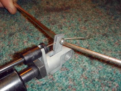
Snappi Pushchair Workshop Manual
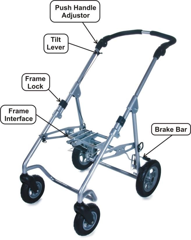
Fig 0.1 Complete Pushchair (size 1 shown)
Document No: 053-06 v14 Page 2 of 88 February 2021
Snappi System Workshop Manual.doc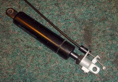
Snappi Pushchair Workshop Manual

                              Fig 0.2 Chassis (size 1 shown)

                             Fig 0.3 Seat Unit (Size 1 shown)

Document No: 053-06 v14                 Page 3 of 88            February 2021
Snappi System Workshop Manual.doc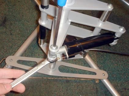
Snappi Pushchair Workshop Manual

                  Fig 0.4 Folded System - Complete (size 1 only)

                   Fig 0.5 Folded System - 2 part fold (all models)

Document No: 053-06 v14               Page 4 of 88                    February 2021
Snappi System Workshop Manual.doc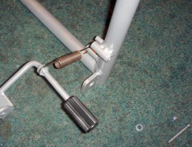
Snappi Pushchair Workshop Manual

                                 CONTENTS
  Item                          Description                                Page
    1        Your Snappi Pushchair Workshop Manual                         7-9

    2        Transit Packaging                                             9 - 10

    3        Tools & Torque Settings                                         10

    4        Preparing for use and operation                                 11
             4.1 Unfolding the frame                                         11
             4.2 Brakes                                                      11
             4.3 Fitting Seat to the Chassis                                 11
             4.4 Tilt in Space                                               12
             4.5 Seat Back Recline                                           12
             4.6 Seat standard adjustments                                   12

    5        Final Checks                                                    13

    6        Maintenance                                                    13
             6.1 Routine maintenance                                        13
             6.2 Six monthly maintenance                                   13-14
             6.3 Three yearly maintenance                                   14

    7        Repairs                                                         14
             7.1A Rear Wheels – fitting to a chassis with an old-style       15
             (i.e. not pin-lock)
             7.1B Rear wheels – fitting to a chassis with a pin-lock      16 - 17
             brake
             7.2 Castor assembly and front tie down bracket               16 - 17
             7.3A Original Brake assembly                                 17 - 18
             (pushchairs supplied before June 2015)
             7.3B Pin Brake Assembly (pushchairs supplied after           18 – 23
             June 2015)
             7.4 Chassis gas spring                                       23 – 24
             7.4.1 Cable End Fitting                                      24 – 26
             7.4.2 Tilt Cable (just the cable)                            26 – 27
             7.4.3 Tilt Cable (complete)                                    28
             7.5 Seat gas spring                                          29 – 30
             7.5.1 Lock Back Recline                                      30 – 32
             7.6 Seat Interface                                           32 – 33
             7.7 Replace Push Handle Adjustors                            33 – 34
             7.8 Knee Angle Adjustor                                      35 – 36
             7.9 Footrest Parts                                             36
             7.9.1 Footrest Stems                                         36 – 37

Document No: 053-06 v14                Page 5 of 88                      February 2021
Snappi System Workshop Manual.doc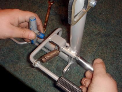
Snappi Pushchair Workshop Manual

             7.9.2 Footrest Tray                                   37 – 38
             7.9.3 Footrest Slide Assembly                           38
             7.10 Locking Slider                                   39 – 42
             7.11 Sun Canopy Assembly                              43 – 47
             7.12 Fitting Vertical Cylinder Carrier                47 – 53
             7.13 Removing and Fitting Snappi Playtray Receiver    53 – 54
             Brackets

    8        8.1 Forward to Rearward Conversion                    54 – 58
             8.2 Rearward to Forward Conversion                    59 – 64

    9        Fit the minimiser kit to the Snappi Seat              64 – 79

   10        Convert a Snappi Minimiser to a Standard Seat         80 – 87

   11        Cleaning                                                 88

   12        Parts List                                               88

Document No: 053-06 v14               Page 6 of 88                February 2021
Snappi System Workshop Manual.doc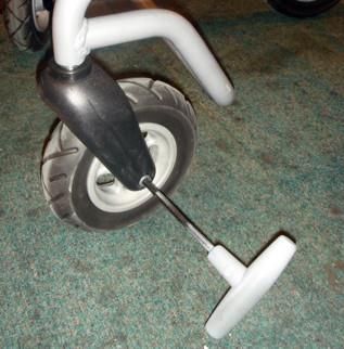
Snappi Pushchair Workshop Manual

1: Your Snappi Wheelbase / Interface Workshop Manual
The purpose of this manual is to help you get the best from your pushchair. It
does this by telling you how to complete those maintenance and repair tasks
that can be carried out by a competent person. The manual also tells you
when you should contact the manufacturer who is:

                                     Tendercare Ltd.
                       PO BOX 3091, Littlehampton, BN16 2WF
                       Tel: (01903) 726161 Fax: (01903) 734083
                             Email: info@tendercareltd.com
                              Web: www.tendercareltd.com

IMPORTANT:
This manual must be read and used in conjunction with the user manual.

The Wheelbase is made of a strong and lightweight aluminium alloy,
minimising weight and providing a very rugged frame. The wheelbase
provides a tilt in space facility and has 2 fixed rear wheels and 2 castor
wheels at the front for easy steering.

The Seat unit offers best in class growth, thanks to its versatile design and
large ranges of adjustments to all supports. It has an easy to remove,
breathable cover, and comes supplied with a hip belt as standard.

Seat adjustments (please see table below for details of adjustment ranges):
Seat depth adjustment, depth and length adjustable Hip Guides, Back Height
adjustment, Independent back recline (using an easy to operate gas strut
mechanism) and depth & angle adjustable Footrest. The seat also includes an
interface allowing it to be quickly fitted and removed from the wheelbase, and
like the entire Snappi range, includes all the latest safety mechanisms
(including an innovative 2 stage release to prevent little fingers causing
accidents).
The following accessories for use with the Snappi Pushchair are available
from Tendercare Ltd.

Wheelbase Accessories: Equipment carrying tray, Shopping basket, and
Rain-hood.

Seat Accessories: Height and width adjustable wrap around Lateral Supports,
Butterfly chest harness, Foot and Toe Straps, Pommel, Play Tray, Standard
Headrest, Extra recess Headrest, and Occipital roll Headrest.

These instructions apply to all sizes.

Document No: 053-06 v14               Page 7 of 88                       February 2021
Snappi System Workshop Manual.doc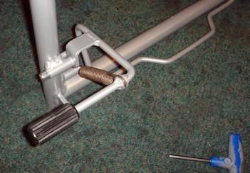
Snappi Pushchair Workshop Manual

Snappi Seat Adjustments
        Support         Snappi Pushchair Size         Snappi Pushchair Size
                                  1                             2
Seat Depth              195-295mm                     290-390mm
Seat Width              190-290mm                     250-350mm
Backrest Height         450-620mm                     540-700mm
Footrest Depth          150-280mm                     215-360mm
Back Recline Angle      90°- 135°                     90°- 135°
Knee Angle*             -15°- 90°                     -15°- 90°
Total System Weight     17Kg                          19Kg
Maximum Carry           40Kg                          40Kg
Weight**

IMPORTANT:
* Knee angle adjustable in 15° increments
** Maximum carry weight is defined as the user weight, plus any
accessories / equipment which may be fitted or carried on the chassis. The
weight of the Snappi seat has been taken into account with these weights
and you do not need to make any deduction for the Snappi Seat. Warning:
Never exceed the maximum stated carry weight.

                                          Snappi Wheelbase Open
   Dimensions (mm)
                                       Size 1                Size 2
              A                         944                   960
              B                         571                   684
              C                         992                   998

Document No: 053-06 v14               Page 8 of 88                February 2021
Snappi System Workshop Manual.doc
Snappi Pushchair Workshop Manual

                                          Snappi Wheelbase Folded
    Dimensions (mm)
                                        Size 1                Size 2
              D                          771                   798
              E                          571                   684
              F                          573                   560

Please note sizes for the complete pushchair are not given, as the overall size
of the pushchair is dependant on the specific settings of the seat.

All sizes and weights are given as a guide. Tendercare ltd reserves the right
to amend specifications at any time as part of their product development
programme.

2: Transit Packaging

The wheelbases and seat unit are delivered together in a cardboard carton.
This measures 680mm wide x 480mm deep x 1030mm high and weighs
approximately 18Kg (size 1) or 20Kg (size 2).

WARNING:
The transit carton is quite bulky so moving and unpacking must be done
with care. Observe all lifting and handling regulations.

Stand the carton upright making sure it is supported and cannot fall over.
Open the carton and remove any packages or packing materials, which could
obstruct the removal of the wheelbase. Remove the wheelbase.

Item                       Component                  QTY.     Yes        No
1        Size 1 or 2 Wheelbase                         1
2        Size 1 or 2 Seat Unit                         1
3        User Manual                                   1
4        5mm Alan key                                  1

Document No: 053-06 v14                Page 9 of 88                  February 2021
Snappi System Workshop Manual.doc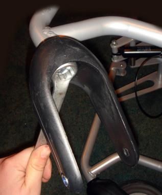
Snappi Pushchair Workshop Manual

The following items should be fitted to the seat as standard:

Item                   Component                            QTY.      Yes         No
5         Hip guide covers                                   2
6         Seat Base Cover                                    1
7         Seat Back Cover                                    1
8         Side Pads                                          2
9         Hip Belt                                           1

Please note, accessories such as lateral supports or harnessing that were
ordered at the same time as the pushchair, will be included in the main
package.

Larger accessories will be packaged in separate cartons (e.g. the rain cover).

IMPORTANT:
    ❖   If any items are damaged or missing, then please contact Tendercare,
        preferably by email at info@tendercareltd.com or alternatively please call us on
        (01903) 726161 within 36 hours of delivery.

After unpacking and checking you have all components and they are in good
condition dispose of the packaging at your local recycling centre. Alternatively
retain and reuse.

3: Tools and Torque Settings
The following tools are required to dismantle, reassemble and repair the
pushchair:

Spanners and sockets:               8mm, 10mm, 13mm and 19mm
Hexagon Keys:                       3mm, 4mm, 5mm and 6mm
Torque Wrench:                      Range 0 to 50 Nm
Screwdrivers:                       2 small flat blade screwdrivers

                         Torque Settings if not specified:
                    Spanner Size (mm)           Torque (Nm)
                            8                       10
                           10                       15
                           13                       25
                           19                       50

Document No: 053-06 v14                    Page 10 of 88                     February 2021
Snappi System Workshop Manual.doc
Snappi Pushchair Workshop Manual
4: Preparing for use and operation
WARNING:
When opening or folding the wheelbase, ensure that you hold the frame
so that you avoid any danger of catching your fingers in moving parts.
The following pre-delivery procedures should be carried out to check that the
wheelbase and seat unit have not suffered damage during transit and that all
features operate satisfactorily. Refer to the user manual for detailed
instructions on performing each action.
4.1 Unfolding the Frame
Unfold and assemble the frame: Follow the instructions in section 4.1 of the
user manual
Checks:
• Make sure all joints move freely
• Make sure the frame locks latch correctly
• Check that the push handle adjustors work
• Ensure that all fixings are secure and that the frame has not been bent
or otherwise damaged during transit.
4.2 Brakes
Test the brakes: Follow the instructions in section 4.2 of the user manual
Checks:
• Make sure the brakes work correctly
• Check that the fixing bolts are secure
WARNING:
The break mechanism is spring loaded so care must be taken when
operating it.
4.3 Fitting the seat to the chassis
Fit the seat unit into the chassis following the instructions in section 4.3 of the
user manual.
Checks:
• Check that the spring clips move freely and snap back to their closed
position when the lever is released
• Make sure the seat interface latches down and locks securely to the
frame
• Check that the secondary latch mechanism functions correctly
• Check that the seat interface releases correctly and that there is not
excessive friction on the lever when releasing it from the frame
Document No: 053-06 v14 Page 11 of 88 February 2021
Snappi System Workshop Manual.docSnappi Pushchair Workshop Manual
4.4 Tilt In Space
Test the tilt in space mechanism: Follow the instructions on section 4.4 of the
user manual.
Checks:
• Make sure that the cable mechanism works correctly and that the cable
is not trapped in any way.
• Check that the centre section tilts correctly and locks throughout its
adjustment range.
• Check that the 4 bolts that mount the centre section into the frame are
secure.
IMPORTANT:
❖ Always support the seat when tilting, as the gas springs can be quick to
operate. If the seat is not supported, it may move swiftly and could cause the
occupant distress.
4.5 Seat back recline:
Test the seat back recline mechanism is working correctly by following the
instructions in section 5.1.3 of the user manual.
Checks:
• Make sure the gas spring moves freely through its entire range of
motion when released
• Ensure that the gas spring locks when the lever is released.
• Check that the fixing bolts for the gas spring are secure and that there
is not excessive play between the gas spring and the mounting points
on the seat when locked.
4.6 Seat standard adjustments:
All adjustments to the seat are made using hand wheels, or the 5mm hexagon
key provided. Test the adjustment ranges of the seat base, hip width, footrest
depth, footrest angle and back height as detailed in sections 5.1.1 – 5.1.3 of
the user manual.
Checks:
• Ensure all elements are free to move over their entire adjustment range
(note that the cover and harnessing may need adjusting to allow this-
instructions on how to adjust these are given in section 5 of the user
manual)
• Check that all elements lock correctly
• Check that the framework is square and has not been damaged during
transit.
Document No: 053-06 v14 Page 12 of 88 February 2021
Snappi System Workshop Manual.docSnappi Pushchair Workshop Manual
5: Final checks
1. Check that the pelvic strap or harness is secure and adjusted correctly.
2. Check that the cover is correctly fitted.
3. Check that the seat unit is located and locked correctly in the chassis.
4. Ensure the safety catch is locked.
6: Maintenance
Should a problem be found when carrying out the regular checks, it should be
immediately reported to the issuing authority or Tendercare Ltd.
6.1 Routine maintenance
The user’s family can easily carry out the following tasks. No tools are
required.
1. Always wipe the wheelbase and seat frame dry. Never put them away
damp.
2. Check operation of the brake, folding and reclining mechanisms
(weekly).
3. Clean frame when necessary (we suggest at least once a week).
If you find any faults refer to your issuing authority or Tendercare Ltd.
6.2 Six-monthly maintenance
Only someone who is a competent tradesman or repairer should carry out this
work. If a major fault is found stop using the wheelbase until it has been
corrected.
1. Fold and open the wheelbase. Check that all movements through the
folding range are free. Examine frame for any damage.
2. Check operation of the wheelbase tilt in space mechanism.
3. Examine nuts, bolts, pivots and frame plugs for tightness and general
condition.
4. Examine brake assembly for wear, damage and correct operation.
5. Examine tyres for sharp objects, cuts or splits.
6. Examine castor and wheel bearings for excessive wear.
7. Check castors and rear wheels for free rotation, security and
accumulation of fluff and grit. Remove any fluff and grit with a dry lint
free cloth.
Document No: 053-06 v14 Page 13 of 88 February 2021
Snappi System Workshop Manual.docSnappi Pushchair Workshop Manual
8. Check the Interface fits securely into the frame, and that it is not worn
or damaged.
9. Check the interface clips to ensure they can rotate freely and that the
springs return the clips to the closed position when released.
For all other repairs refer to your issuing authority or Tendercare Ltd.
6.3 Three-yearly maintenance
1. The seat and chassis gas strut release heads are cast aluminium and
so we recommend this is routinely replaced every three years.
7: Repairs
Only an authorised repairer should carry out the following repairs.
1. Repairs: For all repairs contact your issuing authority
2. Major repairs: For all major repairs e.g. bent or damaged frame, the
wheelbase / interface should be returned to the factory. Contact
Tendercare ltd, customer services on 01903 726161, or email to
info@tendercareltd.com
3. Factory replacement components should be used in all repairs. These
are available from Tendercare. Please refer to the parts lists at the end
of this manual (section 10) for details of replacement parts.
Important points when performing a repair:
1. Do not reuse Nylock nuts, always replace with a new nut
2. Always use Loctite thread locking compound grade 241 or 243 on all
threads when reassembling any part of the system.
3. Always use the recommended component parts available from
Tendercare Ltd.
4. Do not attempt to correct bent framework or perform any modifications
to welded parts. If any main framework sections are bent or damaged
please return the product to the factory.
Document No: 053-06 v14 Page 14 of 88 February 2021
Snappi System Workshop Manual.docSnappi Pushchair Workshop Manual
7.1A: Rear Wheels – fitting to a chassis with an old-style (i.e. not pin-
lock)
Replace if damaged or worn. To change the rear wheel:
Fig 7.1.1 • Remove the wheel cap using
a small screwdriver (see fig
8.1.1 left)
• Note the position of the axle
spacer and washers
• Using a 19mm spanner, undo
the axle bolt and remove the
wheel from the frame (see fig
8.1.2 below)
• To fit the new wheel: Ensure
the large nylon washer is
placed under the head of the
M12 bolt.
Fig 7.1.2
• Fit this through the wheel and
slide the axle spacer onto the
protruding bolt.
• Place a new M12 Nylock nut
into the axle support, and
screw the bolt into the nut
(the axle support will prevent
the nut from turning)
• Tighten to 35Nm with a
torque wrench
• Finally push fit the wheel cap
over the bolt head.
Document No: 053-06 v14 Page 15 of 88 February 2021
Snappi System Workshop Manual.docSnappi Pushchair Workshop Manual
7.1B: Rear wheels – fitting to a chassis with a pin-lock brake
Replace if damaged or worn. To change the rear wheel:
Fig 8.1.1
• Remove the wheel cap using a
small screwdriver (see fig 8.1.1
left)
• Using a 19mm spanner, undo
the axle bolt and remove the
wheel from the frame (see fig
8.1.2 below)
Fig 8.1.2
• Place the M12 bolt through the
rear wheel, apply a pea-sized
amount of loctite 243 to the
bolt thread, and thread into the
threaded hole in the frame.
• Tighten to 35Nm with a torque
wrench
• Finally push fit the wheel cap
over the bolt head.
7.2: Front Castors and Front Tie Down
Replace if damaged or worn. To change the front castor:
Fig 7.2.1
• Remove the wheel by
unscrewing the M8 socket cap
bolt using a 5mm hexagon key.
• Next remove the castor
housing using a 19mm
spanner
Document No: 053-06 v14 Page 16 of 88 February 2021
Snappi System Workshop Manual.docSnappi Pushchair Workshop Manual
• To fit the new castor, first Fig 7.2.2
ensure the wheel is removed
from its housing.
• Next fit the hosing to the frame
and tighten to 35Nm with a
torque wrench
• Screw the new wheel into the
castor housing using a 5mm
hexagon key and tighten firmly
(no other tool is required to fit
the wheel as the castor
housing includes a captured
nylock nut).
• Snappi pushchairs ordered
Fig 7.2.3 after November 2012 come
supplied with a front tie down
bracket. This fits between the
front castor and frame.
• To replace the front tie down
bracket, remove the front
castor as detailed above. Slide
the tie down bracket over the
bolt with the loop facing the
front of the pushchair, and refit
the castor to the frame.
• Always apply Loctite thread
locking compound onto the
castor bolt before refitting to
the frame.
7.3A: Original Brake Assembly (pushchairs supplied before June 2015)
Replace the brake bar if it is bent or damaged. The springs may also be
replaced if corroded or stretched.
IMPORTANT
❖ The brake system uses two high-tension springs. Care must be taken when
working on the brake mechanism. The following instructions are the
recommended method for dismantling the brake system to safely release the
tension on the springs. If you are not confident to work on this assembly
please return your frame to the Tendercare factory.
Document No: 053-06 v14 Page 17 of 88 February 2021
Snappi System Workshop Manual.docSnappi Pushchair Workshop Manual
To dismantle the brake assembly:
• Put the break into the “off”
Fig 7.3.1 position, and remove the 2 rear
wheels as detailed in section
8.1 of this manual.
• Next flip the brake bar down to
the “on” position. As there are
no wheels the bar will move
much further and release most
of the tension on the springs
as shown in figure 8.3.1 (left).
Fig 7.3.2
• Undo the brake bar pivot bolt
using a 10mm spanner and
4mm hexagon key. Care must
be taken at this stage, as
there will still be some
tension on the spring.
• Once the 2 pivot bolts are
released the bar will drop down
Fig 7.3.3 and rest against the frame.
• To release the springs, lift the
bottom of the brake bar up and
round past the frame bar as
shown in figure 8.3.3. Now the
tension on the spring will be
fully released and they can
easily be unhooked.
• To refit a new brake bar or
springs, follow the reverse of
this procedure.
7.3B: Pin Brake Assembly (pushchairs supplied after June 2015)
Replace the brake bar if it is bent or damaged. The springs, actuators and
guide bushes can also be replaced if warn.
IMPORTANT
❖ The brake system uses two compression springs. Care must be taken when
working on the brake mechanism. The following instructions are the
recommended method to safely dismantle the brake assembly. If you are not
confident to work on this assembly, please return your frame to the Tendercare
factory.
Document No: 053-06 v14 Page 18 of 88 February 2021
Snappi System Workshop Manual.docSnappi Pushchair Workshop Manual
To remove the pin brake. First set to
the brake to the ON position (for
instructions how to do this please
refer to the user manual).
Then, remove the rear wheels (see
section 7.1).
Fig 7.3.4
As the brake is set to ‘on’ the ends of
the lock pins will be accessible. Use a
pair of grips to pull one of the pins out
against the spring to reveal the 2mm
‘assembly’ hole in the brake pin (see
Fig 7.3.5, left).
Fig 7.3.5
Push a 2mm pin through the
assembly hole (pins will be provided
with replacement brake parts).
This will hold the brake pins in the
fully extended position.
Fig 7.3.6
Using a hex key and spanner / socket
remove the 6 socket button bolts that
secure the brake actuator to the
actuator caps as shown (see Fig
7.3.7, left).
Fig 7.3.7
Document No: 053-06 v14 Page 19 of 88 February 2021
Snappi System Workshop Manual.docSnappi Pushchair Workshop Manual
With all the bolts removed, slide the
brake actuator caps towards the
middle of the frame and remove them
as shown (see fig 7.3.8, right).
Fig 7.3.8
Fig 7.3.8 Left: The brake bar with the
actuator caps removed.
Fig 7.3.9
You will now be able to remove the
brake bar assembly from the frame.
Fig 7.3.10
Undo the 2 M4 screws securing the
brake actuators to the brake bar using
a hex key as shown (see fig 7.3.11,
left).
Fig 7.3.11
Document No: 053-06 v14 Page 20 of 88 February 2021
Snappi System Workshop Manual.docSnappi Pushchair Workshop Manual
Fig 7.3.12 Right: The brake bar
removed from the actuators.
Fig 7.3.12
To remove the lock pins, springs and
guide bushes: First place a block of
wood on the inside of the frame as
shown in fig 7.3.13 (this is to provide
a stop for the brake pin when the
spring is released).
Fig 7.3.13
With the block of wood held in place,
pull out the 2mm pin to release the
brake pin.
With the pressure of the spring safely
released, now push the brake pin,
spring and guide bush out of the
mounting on the frame.
Fig 7.3.14
Document No: 053-06 v14 Page 21 of 88 February 2021
Snappi System Workshop Manual.docSnappi Pushchair Workshop Manual
To re-assemble the pin brake assembly:
Place the wheelbase with the front
frame down onto a flat surface as
shown (see fig 7.3.15, left). This
provides easier access to the brake
mounting points.
Fig 7.3.15
Slide the guide bush, spring and
brake pin into the mounting point as
shown (see fig 7.3.16, right).
Fig 7.3.16
Ensure you have a pair of grips and
the 2mm pin available.
Push the brake pin into the frame
against the spring as shown (see fig
7.3.17, left).
Fig 7.3.17
Document No: 053-06 v14 Page 22 of 88 February 2021
Snappi System Workshop Manual.docSnappi Pushchair Workshop Manual
Pull the brake pin out of the frame
with the grips to expose the assembly
hole.
Push the 2mm pin through the hole to
lock the pin in place.
Repeat this for both sides, and then
follow the reverse of the dismantling
instructions to assemble the rest of
the brake assembly. Fig 7.3.18
7.4: Chassis gas spring
Replace the gas spring if it is damaged or worn. Please note, as the gas strut
release head is cast aluminium, we recommend this is replaced every three
years.
To remove the gas strut:
Fig 7.4.1
• Lift the frame onto a suitable
workbench and lay it on its
side
• Using a 13mm spanner and
5mm hexagon key undo the
gas strut fixing bolts. Take note
of the position of the washers
and spacers.
Fig 7.4.2
• To remove the Bowden cable,
use 2 small screwdrivers to
release the “screw nipple” (see
right) and then slide it along
the excess cable as shown in
fig 7.4.1.6 (next page).
Document No: 053-06 v14 Page 23 of 88 February 2021
Snappi System Workshop Manual.docSnappi Pushchair Workshop Manual
• Place a small screwdriver
between the gas spring and
the plastic clip on the Bowden
cable and lever the clip away
Fig 7.4.3
from the spring housing.
• To fit the new gas spring, clip
the cable onto the head of the
new spring, slide the screw
nipple into the lever and
tighten the lock nut. Do not
overtighten. Then remount in
the same way as the original
spring was fitted.
• Once fitted, test the operation
of the gas strut as detailed in
section 4.3 of this manual
7.4.1 Change the end fittings on the gas spring cable:
To replace the end fitting on the gas spring:
Fig 7.4.1.1
To order just the end fittings, order B
part SN7300B (please see the Snappi
Chassis parts list). Alternatively a
whole tilt cable assembly can be
ordered under part code SN3700.
A
Right: The end fittings as supplied;
A- aluminium crimp fitting B- the
plastic cable mounting
Document No: 053-06 v14 Page 24 of 88 February 2021
Snappi System Workshop Manual.docSnappi Pushchair Workshop Manual
Fig 7.4.1.2
First cut the end of the steel cable
and crimp fitting off of the old cable
using a pair of wire cutters.
Fig 7.4.1.3
Next loosen the ‘screw nipple’ with a
small screwdriver and slide off the
end of the cable (please retain this
end fitting).
Fig 7.4.1.4
Remove the old cable end fitting
using a screwdriver and slide off the
end of the cable.
Fig 7.4.1.5
Next take the new end fitting and
slide onto the end of the cable, then
push fit back onto the clip point on the
gas spring (see below).
Document No: 053-06 v14 Page 25 of 88 February 2021
Snappi System Workshop Manual.docSnappi Pushchair Workshop Manual
Fig 7.4.1.6
Slide the ‘screw nipple’ back onto the
cable, into the scoop in the gas spring
head lever, making sure all the slack
is taken up in the cable, tighten with
the screwdriver. Finally grip the
aluminium end crimp in a large pair of
grips, slide over the cut end of the
cable and squash to prevent the
cable end from fraying.
Finally test the operation of the gas spring, if the gas spring will not release,
check the cable for slack and adjust the ‘screw nipple’ as required. For more
details on the correct operation of the tilt mechanism please refer to the user
manual.
7.4.2: Replace the tilt cable, leaving the release lever in place:
Replace the tilt cable if damaged or worn. This is the preferred method
providing the release lever is OK. If the release lever needs to be replaced
follow the instructions in section 7.4.3.
Fig 7.4.2.1
First release the ‘screw nipple’ on the
old tilt cable using 2 screw drivers.
Fig 7.4.2.2
Slide this down to the end of the
cable to provide some slack as shown
(see left). Note the new cable will also
need to be loosened off.
Document No: 053-06 v14 Page 26 of 88 February 2021
Snappi System Workshop Manual.docSnappi Pushchair Workshop Manual
Fig 7.4.2.3
Using a small screwdriver, separate
the cable mounting from the gas
spring as shown (right).
Fig 7.4.2.4
Slide the cable cover and conical
mounting point down as far as it will
move, taking up the spare cable from
the bottom so that the cable is
exposed at the top.
Fig 7.4.2.5
Lift the lever up, and slide the cable
out of the slot in the lever mounting.
Unhook the cable from the lever, and
Fig 7.4.2.6
then slide the cable out from the
frame taking note of the routing (the
correct routing is via the rear D ring,
up and through the upper to rear
frame joint).
Note that the replacement cable is
supplied with the mounting and lever,
separate the new cable from the
mounting and then fit onto the original
mounting on the frame, by following
the reverse of this procedure.
Document No: 053-06 v14 Page 27 of 88 February 2021
Snappi System Workshop Manual.docSnappi Pushchair Workshop Manual
7.4.3: Replace the tilt cable and release lever assembly:
Replace the entire cable and lever assembly if the lever is damaged or worn.
Note that to do this you must first remove the push handles as detailed in
section 7.7
Fig 7.4.3.1
First remove the push handle
adjustors from the frame (see
section 7.7 for more details).
Leave the adjustors fitted to the
push handle, and refit once the
cable has been replaced.
Fig 7.4.3.2
After removing the push handle, drill
off the 2 pop rivets securing the
release lever to the frame.
Separate the cable from the gas
spring, and remove the entire cable
taking note of its routing (for more
details on releasing the cable from the
frame, see section 7.4.1 and 7.4.2
above).
Fit the new lever with 2 x 4.8mm a 14mm black pop rivets, and route the cable
via the top frame to rear frame joint and rear D ring as before, and re-attach to
the gas spring following the instructions detailed in section 7.4.1 and 7.4.2 of
this manual.
Document No: 053-06 v14 Page 28 of 88 February 2021
Snappi System Workshop Manual.docSnappi Pushchair Workshop Manual
7.5: Seat gas spring/strut
Replace the gas spring if it is damaged or worn. Please note, as the gas strut
release head is cast aluminium, we recommend this is replaced every three
years.
To remove the gas strut (shown in Fig 7.5.1):
Fig 7.5.1
• Lift the seat onto a suitable
workbench and sit it on its
interface with the seat back angle
set at 90 degrees.
• Using 2 x 13mm spanners undo
the gas strut fixing bolts. Take
note of the position of the
washers and spacers.
• Remove the release lever; undo Fig 7.5.2
the release head by placing a
bar (e.g. shank of a screwdriver)
through the mounting hole in the
head, and loosen with a 13mm
spanner as shown in Fig 7.5.2.
• Next, unscrew the gas spring
from the head and remove the
release lever.
Fig 7.5.3
• To reassemble the new gas
spring, place the release lever
into the head, and screw in the
gas spring so that the pin on the
end of the gas spring locates Dynamic strut
restrictor
into the notch in the lever. Note:
for Snappi seats fitted with the
dynamic gas strut, you will need
to place the dynamic strut
restrictor between the body of Gas strut body
the gas strut and the m8 lock
nut (see Fig 7.5.3).
Document No: 053-06 v14 Page 29 of 88 February 2021
Snappi System Workshop Manual.docSnappi Pushchair Workshop Manual
Fig 7.5.4
• Tighten the m8 lock nut until there
is no movement between the pin
and release lever, then unscrew
the gas spring by ¼ of a turn. This
ensures that there is the correct
amount of play between the pin
and release lever. Do not over
tighten.
M8 lock nut
• Finally secure the release head by placing a bar though the mounting
hole, and tighten with the 13mm spanner.
IMPORTANT:
❖ Ensure that there is a small amount of play between the release lever and pin
on the end of the gas spring. If this is too tight, the gas spring may not lock
correctly, or could have the tendency to ‘creep’ when in a locked position.
7.5.1: Lock the Back Recline
The following instructions detail how to remove the back recline adjustment
lever in order to lock the back recline in a single position.
• First, position the back rest to
the desired fixed position*
(please refer to the section
5.3.1 of the user manual for
how to adjust the angle of the
backrest).
• Next, use a 13mm spanner to
loosen the black nut on the gas
strut (3 turns should be
sufficient) as shown (see Fig
7.5.1.1, left).
Fig 7.5.1.1
Document No: 053-06 v14 Page 30 of 88 February 2021
Snappi System Workshop Manual.docSnappi Pushchair Workshop Manual
• Using a pair of 13mm
spanners, remove the M8 bolt
that secures the top of the gas
spring the back rest of the seat
as shown (see Fig 7.5.1.2,
right). Take note of the
positions of the spacers,
washers and nuts.
Fig 7.5.1.2
• Hinge the gas spring away
from the back of the chair (it
will pivot on the lower bolt) and
unscrew the head a few turns
and then remove the lever.
Fig 7.5.1.3
• Screw the head back onto the
gas spring and lock in place
using the black nut and a
13mm spanner.
• Fix to the backrest using the
M8 bolt, replacing the washers
and spacers in their original
position.
Fig 7.5.1.4
Document No: 053-06 v14 Page 31 of 88 February 2021
Snappi System Workshop Manual.docSnappi Pushchair Workshop Manual
Important:
*The Snappi Seat is only crash tested with the backrest set to a 90 degree angle. If the
backrest angle is fixed at any angle other than 90 degrees, the seat can no longer be
used for transport in an adapted vehicle.
7.6: Seat Interface
Replace the interface clips if they are damaged or bent; replace the springs if
they are stretched or overly soft in operation.
IMPORTANT
The seat interface uses 2 strong torsion springs that are under load. Care must be
taken when working on the interface clip mechanism. The following instructions are
the recommended method for dismantling the assembly to safely release the tension
on the springs. If you are not confident to work on this assembly please return your
frame to the Tendercare factory.
To dismantle the interface:
Fig 7.6.1
• Loosen the front screws from
the mounting using a 4mm
hexagon key as shown (right).
• Remove the rear as the
tension on the 2 torsion
springs must be released
before removing the clip
mechanism from the interface
frame.
7.6.2
To release the tension on the springs:
• Rotate the clips forward and lift
the frame so that it pivots on
the 2 loosened front screws.
Keep lifting until the 2 spring
arms are released from the
interface frame cross bar, as
shown (left)
• Once the springs have been released, remove the 2 front screws using
a 4mm hexagon key. The interface clip assembly can then be easily
taken apart by sliding off the 2 mounting blocks, springs and washers.
Document No: 053-06 v14 Page 32 of 88 February 2021
Snappi System Workshop Manual.docSnappi Pushchair Workshop Manual
Fig 7.6.3
Take note of the position of the 2 chamfers of the mounting blocks as these
MUST be put back in the correct orientation or the interface mechanism will
not function properly.
Also take careful note of the orientation of the springs- the springs are handed
and must be re-fitted correctly or there will not be sufficient tension on the
mechanism to close the clips.
To reassemble the interface follow the reverse of these instructions and test
as detailed in section 4.4 of this manual.
7.7: Replace Push Handle Adjustors
Replace if damaged, or remove and refit when changing the tilt cable and
mounting lug (see section 7.4.3 above).
Fig 7.7.1
First Drill off the 8 x pop rivets
securing the old adjustor with a 5mm
drill, then separate the adjustors from
the frame and push handle.
Upend the frame and remove the rivet
ends from inside the tube.
Document No: 053-06 v14 Page 33 of 88 February 2021
Snappi System Workshop Manual.docSnappi Pushchair Workshop Manual
Fig 7.7.2
Take the new adjustor and tap onto
the frame using a mallet until the
holes in the adjustor line up with the
hole in the frame.
Ensure that the adjustor is positioned
so that the round body is facing down
and that the release button is to the
outside of the frame.
Fig 7.7.3
Note the fit of the adjustor is very
tight, if it is not possible to get the
hole to fully line up it may be
necessary to clear the holes using a
5mm drill bit.
Fig 7.7.4
Secure the new adjustors onto the
frame with 4 x 4.8mm x 14mm black
pop rivets.
Next fit the push handle into the top
of the adjustors (ensuring that both
adjustors are set at the same angle),
tap down with the mallet and secure
with a further 4 x 4.8 x 14mm black
pop rivets.
Fig 7.7.5
Left: The new push handle adjustor
fitted to the frame.
Document No: 053-06 v14 Page 34 of 88 February 2021
Snappi System Workshop Manual.docSnappi Pushchair Workshop Manual
7.8: Knee Angle Adjustor
Replace the seat knee angle adjustor if damaged or worn.
Fig 7.8.1
The replacement knee angle adjustor
comes supplied with: 1 x M5 x 30mm
socket button bolt, 1 x M5 x 35mm
socket button bolt, 2 x M5 Nylock
Dome nuts, 4 x M5 Form A Washers
Fig 7.8.2
Set the footrest to a horizontal
position (i.e. in line with the seat
base) and place the whole seat onto
a flat surface.
Undo the nut and bolt securing the
footrest rod, taking note of the
position of the bolt head and washers,
using a 3mm hexagon key and an
8mm spanner.
Fig 7.8.3
Next separate the footrest rod from
the adjustor as shown (right).
Fig 7.8.4
Undo the rear bolt securing the knee
angle adjustor (this bolt goes through
the play tray adaptor), again taking
note of the position of the washers
and nuts etc. Remove the bolt then
slide the knee angle adjustor off of
the frame. Note it may be helpful to
loosen the rear bolt securing the play
tray adaptor if it is difficult to slide the
angle adjustor off of the frame.
Document No: 053-06 v14 Page 35 of 88 February 2021
Snappi System Workshop Manual.docSnappi Pushchair Workshop Manual
Finally, slide the new adjustor onto the frame, and secure using the new bolts
and nuts as supplied (never re use nylock nuts!). Please ensure that the rear
fixing bolt is tightened again if loosened in the previous step, and that the
frame fixing is placed through the play tray adaptor as before.
7.9: Footrest Parts:
If a complete footrest assembly is ordered, it comes supplied with footrest
slide with the tray pre-assembled, footrest stems and the angle adjustors. For
information on fitting these please refer to the instructions given in section 7.8
(for the angle adjustors), and 7.9.1 (for the stems) and 7.9.3 (for the slide ad
tray assembly) below.
7.9.1: Footrest Stems:
To replace the footrest stems:
Remove the seat unit from the
chassis, and place it on its back on a
flat surface (see Fig 7.9.1.1).
Fig 7.9.1.1
Unscrew the self-tapping screws from
the end of the old footrest stems as
shown (see Fig 7.9.1.2).
Fig 7.9.1.2
Document No: 053-06 v14 Page 36 of 88 February 2021
Snappi System Workshop Manual.docSnappi Pushchair Workshop Manual
Make sure the footrest locking screws
are loose, and then slide the footrest
assembly off of the stems (see Fig
7.9.1.3).
Fig 7.9.1.3
Using a 3mm hexagon key and an
8mm socket or spanner, remove the
M5 bolt securing the stem to the knee
angle adjustor (as shown in Fig
7.9.1.4). Take note of the position of
the washers. Then remove the stems.
Fig 7.9.1.4
To fit the new stems: Follow the reverse of this procedure, and fit with a new
Nylock dome nut (never re-use Nylock nuts).
7.9.2: Footrest Tray:
Remove the footrest slide assembly from the pushchair, to do this:
• Remove the 2 x self-tapping screws from the end of the footrest stems.
• Loosen the footrest slide locks
• Slide the footrest assembly off the end of the stems.
For more details on this procedure please refer to section 7.9.1 above.
Document No: 053-06 v14 Page 37 of 88 February 2021
Snappi System Workshop Manual.docSnappi Pushchair Workshop Manual
Place the footrest slide assembly onto
a flat surface.
Using a 5mm drill bit drill off the 6
rivets that secure the plastic tray to
the metal base plate.
Fig 7.9.2.1
Position the new foot tray onto the
base plate, so that the cut out slots in
the tray line up with the holes in the
plate. Using a 5mm drill and the base
plate as a template, drill off the 6
mounting holes in the new foot tray.
Fig 7.9.2.2
Secure the new tray onto the base
plate using 6 x black 4.8 mm rivets
(supplied).
Fig 7.9.2.3
Finally, re-attach the foot tray assembly onto the footrest stems, and secure
with the 2 x self-tapping screws.
7.9.3: Footrest Slide Assembly:
The footrest slide assembly will come pre-assembled complete with the
plastic tray. To fit the new assembly, simply remove the old slide assembly
following the instructions given in section 7.9.1 above. Slide the new
assembly in place and secure back in place.
Document No: 053-06 v14 Page 38 of 88 February 2021
Snappi System Workshop Manual.docSnappi Pushchair Workshop Manual
7.10: Locking Slider:
Replace if damaged or worn:
To remove the old locking slider:
Place the chassis on a flat surface
and fold down as shown (see Fig
7.10.1).
Fig 7.10.1
Undo the bolts that secure the front
frame to the upper frame of the
chassis on both sides (even if only
changing one slider. Please see Fig
7.10.2). Take note of the positions of
the washers and retain for use later.
Fig 7.10.2
The front frame of the chassis will
drop forward providing access to the
frame locking sliders as shown (see
Fig 7.10.3).
Fig 7.10.3
Document No: 053-06 v14 Page 39 of 88 February 2021
Snappi System Workshop Manual.docSnappi Pushchair Workshop Manual
Using a 4mm hexagon key and a 10
mm socket or spanner, undo the M6
nylock dome nut securing the locking
slider to the frame (see Fig 7.10.4).
Remove the bolt, taking note of the
position of the washers.
Fig 7.10.4
Finally lift the slider and spring off the
frame (see Fig 7.10.5).
Fig 7.10.5
To fit the new locking slider:
1 2
Parts required (for one slider): 3
1: 1 x Locking Slider
2: 1 x Locking Slider Spring
3: 1 x M6 Nylock Dome Nut 4
4: 1 x M6 x 50mm Socket Button Bolt
5: 2 x M6 Form A Washers
5
Fig 7.10.6
Document No: 053-06 v14 Page 40 of 88 February 2021
Snappi System Workshop Manual.docSnappi Pushchair Workshop Manual
First, place the spring inside the
locking slider so it sits against the
support splines as shown (see Fig
7.10.7).
Fig 7.10.7
Place the slider and spring onto the
upper frame tube with the locking
point of the slider facing up, slide on
until the fixing hole in the frame lines
up with the back end of the slot in the
slider (see Fig 7.10.8).
Fig 7.10.8
Next, take the M6 x 50mm socket
button bolt and place one of the form
A washers onto it as shown (see Fig
7.10.9).
Fig 7.10.9
Place the hexagon key though the
slot in the slider in-between the spring
coils, and pull the spring back down
the slot so that the fixing hole is clear,
whilst also supporting the slider (see
Fig 7.10.10). If it is not possible to pull
the spring back far enough, lift the
slider off of the frame, rotate the
spring a little and try again. Rotating
the spring will expose different parts
of the coil; rotate until a section of coil
is visible that is close to the top of the
slot, this will allow the spring to be Fig 7.10.10
compressed far enough to clear the
hole.
Document No: 053-06 v14 Page 41 of 88 February 2021
Snappi System Workshop Manual.docSnappi Pushchair Workshop Manual
Whilst still holding the slider and
spring back, push the M6 bolt and
washer through the slider and
mounting hole in the frame with the
bolt head to the inside. Ensure that
the bolt is above the spring and not
going through the coils as shown (see
Fig 7.10.11). The bolt provides the
edge for the spring to work against.
Fig 7.10.11
Place the second washer and the M6
Nylock dome nut onto the other end
of the bolt. Tighten using the 4mm
hexagon key and 10mm socket to the
point that the bolt threads are into the
nylon insert inside the dome nut
(when the thread engages with the
insert the force required to tighten the
nut will increase), but leaving enough
slack that both washers are still free
to turn (see Fig 7.10.12).
Re-assemble the frame, and test the
operation of the mechanism (for
details of operating the frame locking Fig 7.10.12
mechanism, please refer to the user
manual). If the slider is too stiff, the
dome nut might need to be loosened
a little.
Document No: 053-06 v14 Page 42 of 88 February 2021
Snappi System Workshop Manual.docSnappi Pushchair Workshop Manual
7.11: Sun Canopy Assembly:
The following instructions detail how to fully assemble the sun canopy
including the cover. A separate parts list “Snappi Sun Canopy Parts List” is
available on our website should any parts need to be replaced.
1
Left: The sun canopy adjustor parts:
2
1: Large Teeth Adjustor
4 2: Small Teeth Adjustor
3 3: Sun Canopy Spring
5 4: M5 Knurled Thumbscrew
5: M5 x 25 mm Coach Bolt
Fig 7.11.1
Right: the assembled left hand frame
fixing bracket (see Fig 7.11.2).
Fig 7.11.2
Front Bar
Rear Bar
To assemble the sun canopy, lay out
the 2 frame bars and 2 fixing brackets
as shown (see Fig 7.11.3, left).
Fig 7.11.3
Document No: 053-06 v14 Page 43 of 88 February 2021
Snappi System Workshop Manual.docSnappi Pushchair Workshop Manual
Take the front bar and feed into the
front fitting tube in the cover as shown
(see fig 7.11.4, right).
Fig 7.11.4
Left: The front frame bar fitted to the
cover (see Fig 7.11.5).
Fig 7.11.5
Next, take the rear bar and feed into
the rear fitting tube as shown (see fig
7.11.6, right).
Fig 7.11.6
Document No: 053-06 v14 Page 44 of 88 February 2021
Snappi System Workshop Manual.docSnappi Pushchair Workshop Manual
Left: The rear bar fitted into the cover
(see Fig 7.11.7).
Fig 7.11.7
Next, fit the ‘large teeth’ canopy
adjustor onto the end of the front bar
as shown (see Fig 7.11.8, right). Push
the adjustor onto the end of the rod
until the hole in the adjustor lines up
with the square cut out in the end of
the rod.
Fig 7.11.8
Take the coach bolt and push it
through the frame bar and adjustor so
that the square neck of the bolt fits
into the square cut out in the bar.
Take the spring and push onto the
other end of the bolt so that the large
end of the spring fits over the
mounting point on the adjustor as
shown (see Fig 7.11.9, left).
Fig 7.11.9
Document No: 053-06 v14 Page 45 of 88 February 2021
Snappi System Workshop Manual.docSnappi Pushchair Workshop Manual
Take the frame fixing bracket and fit
onto the end of the bolt as shown
(see Fig 7.11.10, right). Note the
brackets are handed and will only fit
one way around. Make sure the
correct hand is used so that the large
teeth on the bracket and plastic
adjustor line up.
Fig 7.11.10
Take the ‘small teeth’ adjustor and fit
over the end of the bolt. Thread the
rear bar over the bolt so that it sits
into the recess in the small teeth
adjustor, and then secure with the
thumb screw as shown (see Fig
7.11.11, left).
Fig 7.11.11
Finally, take the small elastic loop on
the end of the cover, and hook over
the thumbscrew as shown (see Fig
7.11.12, right).
Fig 7.11.12
Document No: 053-06 v14 Page 46 of 88 February 2021
Snappi System Workshop Manual.docSnappi Pushchair Workshop Manual
To change the plastic clips on the
frame fixing bracket, use a 3mm
hexagon key and 8mm socket or
spanner and undo the M5 bolt
securing it in place.
Replace the part as needed, and re-
assemble with the clip facing the front
of the sun canopy in the following
order:
M5 x 35mm bolt, frame fixing bracket,
saddle washer, frame clip, washer
and M5 nylock dome nut (see Fig
Fig 7.11.13
7.11.13, left).
Note do not reuse nylock nuts.
To dismantle the sun canopy follow the reverse of these instructions.
7.12: Instructions to fit a ‘Vertical Cylinder Carrier’ to the pushchair:
The vertical cylinder is suitable for use with o2 cylinders with a maximum size
of BOC CD or equivalent. Note: These instructions only apply if the cylinder
carrier has been supplied after initial delivery of the pushchair. Normally the
carrier is fitted in the factory before dispatch. The following procedure is only
to be carried out by a competent tradesperson.
Fig 7.12.1 left: The carrier is supplied
in 2 parts, a mounting plate (left) and
a curved cylinder support (right).
The mounting plate has to be fitted to
the chassis first, then the cylinder
support is attached to the mounting
once in position.
The kit will be supplied with the
following fixings:
3 x 4.8mm x 14mm black pop rivets
Fig 7.12.1 3 x M6 type t nylock nuts
1 x M6 x 45mm Socket Button Bolt
1 x M6 x 50mm Socket Button Bolt
1 x M6 x 55mm Socket Button Bolt
Document No: 053-06 v14 Page 47 of 88 February 2021
Snappi System Workshop Manual.docSnappi Pushchair Workshop Manual
First: remove the nylock dome nuts
securing the rear right hand transit
bracket and rear to upper frame joint
(see arrows, fig 7.12.2, right).
Fig 7.12.2
Fig 7.12.3, left: ensure the 3 bolts are
left in place as shown.
Fig 7.12.3
Next, apply a strong coloured paint to
the end of the protruding bolts.
Fig 7.12.4
Document No: 053-06 v14 Page 48 of 88 February 2021
Snappi System Workshop Manual.docSnappi Pushchair Workshop Manual
Fig 7.12.5, left: Paint is applied to the
ends of all 3 bolts.
Fig 7.12.5
Offer up the rear of the mounting
plate to the 3 bolts.
Fig 7.12.6
Document No: 053-06 v14 Page 49 of 88 February 2021
Snappi System Workshop Manual.docSnappi Pushchair Workshop Manual
Position the plate such that the
bottom of the mounting place is
above the brake block (in the ‘off’
position), with the side of the plate
sitting vertically. Ensure that the
position of the bolts is clear of the
cylinder support (as the support is
curved, ensuring all 3 holes are at
least 1 inch from the fixing holes will
leave sufficient room for the fixing
screws).
When in a suitable position, press the
mounting plate against the protruding
screws so that the paint leaves a
mark on the place.
Fig 7.12.7
Fig 7.12.8, right: The mounting plate
with 3 holes marked (these have
been highlighted white on the photo
to make them easier to see).
Fig 7.12.8
Document No: 053-06 v14 Page 50 of 88 February 2021
Snappi System Workshop Manual.docSnappi Pushchair Workshop Manual
Drill off the 3 holes with a 6mm drill
bit. These holes can be opened out
slightly larger if there are problems
fitting the plate to the pushchair.
Fig 7.12.9
Next, replace the 3 bolts in the
chassis with bolts 5mm longer
(supplied with the carrier).
The top bolt should be changed from
an M6 x 45mm to M6 x 50mm.
The upper transit bracket bolt needs
to change from M6 x 50 to M6 x
55mm.
Finally the lower transit bolt needs to
change from an M6 x 40mm to M6 x
45mm.
Fig 7.12.10
With the longer bolts in place, attach
the drilled mounting plate to the
chassis (don’t fix at this stage).
Fig 7.12.11
Document No: 053-06 v14 Page 51 of 88 February 2021
Snappi System Workshop Manual.docSnappi Pushchair Workshop Manual
Using a pencil, mark out the area of
overlap between the mounting plate
and the transit bracket as shown (see
Fig 7.12.12, left).
Then remove the mounting plate, and
using a drill / hacksaw cut out the
marked area. This is to ensure there
is sufficient clearance to use the
transit bracket when required.
Fig 7.12.12
Fit the cut and drilled plate back onto
the chassis, and secure with the
supplied 3 x M6 type t nylock nuts as
shown (see Fig 7.12.13, right).
Fig 7.12.13
Finally secure the cylinder support
back onto the mounting plate using 3
x 4.8mm x 14mm black pop rivets
(supplied).
Fig 7.12.14
Document No: 053-06 v14 Page 52 of 88 February 2021
Snappi System Workshop Manual.docSnappi Pushchair Workshop Manual
Fig 7.12.15, right: The vertical
cylinder carrier fitted to the chassis.
Fig 7.12.15
7.13: Removing and Fitting Snappi Playtray receiver Brackets
Snappi playtray receiver brackets are supplied as standard on all Snappi
pushchairs. The below instructions advise, if necessary, how you can remove
and fit these brackets.
How to take off Snappi playtray receiver brackets
1. There are two silver
bolts on the side (by the
receiver brackets, see
photo below), take the
back bolt off first using
the 3mm Allen Key.
Behind this bolt is a
white spacer. Take care
not to lose this spacer.
The spacer may be
lodged in a little, if so,
you can get this out by
turning the playtray
bracket which will loosen
the spacer.
2. To remove the front bolt,
put the 8mm spanner on
the nut which is on the
inside of the bracket (see photo below) and unto the bolt with the Allen
key. Underneath the nut is a washer.
3. Repeat for the other side.
Document No: 053-06 v14 Page 53 of 88 February 2021
Snappi System Workshop Manual.docSnappi Pushchair Workshop Manual
How to put on Snappi playtray receiver
brackets
1. To refit the brackets, take the rear
playtray bolt and put this through
the back hole of the receiver
bracket, put the white spacer on
the bolt. Screw this back into the
frame using the 3mm Allen key
2. Take the front bolt and wiggle it
through the front hole. Tighten
using the 3mm Allen key.
3. Put your washer and nut back on
the end of the bolt and tighten using the 8mm spanner.
4. Tighten both the front and rear bolts with the Allen key until the playtray
bracket doesn’t wobble.
5. Repeat for the other side.
8.1: Forward to Rearward Conversion:
The following instructions allow you to convert the wheelbase from forward to
rearward facing. We recommend that this procedure is only carried out by a
competent tradesperson. Alternatively this pushchair can be returned to the
factory, contact Tendercare for more details.
Please note the wheelbase is not crash tested in the rearward facing position
and cannot be used as a seat in a motor vehicle. When converting to
rearward facing the transit brackets and anchorage point labels must be
removed. Note, when set in the rearward facing position, some of the
accessories will not fit, for more details please refer to the user manual.
The following parts are required to convert the Snappi Pushchair from forward
to reward facing (these are available for purchase from Tendercare ltd):
Part Code Description: Qty:
SKTMB06X35Z M6 x 35 Socket Button Screw 2
SKTMB06X45Z M6 x 45 Socket Button Screw 2
N986M06Z M6 Nylock Dome Nut 4
To convert the wheelbase from forward to rearward facing:
• Remove any seat or interface fitted to the chassis and set the chassis
up in its fully open position on a flat work surface. Set the brake on and
choc the front wheels so they cannot roll forward.
• Next, separate the tilt cable from the gas spring (for details on how to
do this please refer to section 7.4 of this manual).
Document No: 053-06 v14 Page 54 of 88 February 2021
Snappi System Workshop Manual.docSnappi Pushchair Workshop Manual
Undo the 4 M6 bolts securing the side
plates and mid frame into the chassis
using a 4mm hexagon key and a
10mm socket or spanner (see Fig
8.1.1). Take note of the position of the
hanger clip and washers.
Fig 8.1.1
Remove the additional M6 bolts that
secure the rear transit brackets to the
frame and remove the transit bracket
(see Fig 8.1.2). Also remove the
‘anchorage point’ labels.
If fitted, remove the front transit
bracket by removing the front castor
(see section 7.2 of this manual for
details), and remove the front
anchorage label.
Fig 8.1.2
Fig 8.1.3 left: The chassis with the
middle section removed.
Fig 8.1.3
Document No: 053-06 v14 Page 55 of 88 February 2021
Snappi System Workshop Manual.docSnappi Pushchair Workshop Manual
After removing the rear transit
brackets, fit 2 x plastic caps into the
lower holes (see Fig 8.1.4). This is
purely for aesthetics, if required these
caps can be purchased from
Tendercare.
Fig 8.1.4
Rotate the middle section 180
degrees in relation to the frame, so
that the gas spring is facing the rear
of the frame.
Re fit the middle section to the frame,
with the bolt head and basket hanger
to the inside and with a nylon washer
in-between the side plate and frame
(see Fig 8.1.5). Replace the M6 x
50mm socket button screws with 2 x
M6 x 45 socket button screws. Fit the
2 x m6 x 35 socket button screws into
the unused hole below the side plate.
Secure all 4 bolts into the frame with
Fig 8.1.5 new Nylock dome nuts (do not reuse
Nylock nuts).
Fig 8.1.6, right: The mid frame rotated
and re fitted to the frame.
Fig 8.1.6
Document No: 053-06 v14 Page 56 of 88 February 2021
Snappi System Workshop Manual.docSnappi Pushchair Workshop Manual
Next, loosen the 2 M8 bolts that
screw into the main crossbar using a
5mm hexagon key (see Fig 8.1.7).
Note these bolts are secured with
Loctite thread locking compound and
may require some force to loosen
them off.
Fig 8.1.7
Using a 5mm hexagon key and a
13mm socket or spanner, remove the
short M8 bolts that secure the angle
lock plates (see Fig 8.1.8).
Fig 8.1.8
Rotate the middle section so that the
top hole in the angle lock plate lines
up with the hole in the side plate (see
Fig 8.1.9). Secure in this position with
the M8 bolt, washer and a new
Nylock dome nut.
Fig 8.1.9
Document No: 053-06 v14 Page 57 of 88 February 2021
Snappi System Workshop Manual.docSnappi Pushchair Workshop Manual
Finally, remove one of the M8 bolts
that screws into the main crossbar,
apply fresh Loctite and re attach.
Repeat this for the other side.
Fig 8.1.10 right: The frame after
conversion to rearward facing.
Fig 8.1.10
Notes:
• Once the pushchair has been converted to rearward facing it cannot be
used as a seat in a motor vehicle as the pushchair has not been crash
tested in a rearward facing position.
• Some of the accessories are not compatible with the pushchair in its
rearward facing configuration and will not fit. For more details on the
accessories please refer to the user manual.
Document No: 053-06 v14 Page 58 of 88 February 2021
Snappi System Workshop Manual.docYou can also read