Fireplace Construction and Layout

Page created by Dana Russell
 
CONTINUE READING
Fireplace Construction and Layout
CHAPTER 40
                                                                      Fireplace Construction
                                                                      and Layout

I     N    T    R     O      D     U     C     T     I    O     N
Thought was given to the type and location of the fireplace in
Chapter 18 when the floor plan was drawn. As the sections are
being drawn, consideration must be given to the construction
of the fireplace and chimney. The most common construction
materials for a fireplace and chimney are masonry and metal. The
metal, or zero-clearance, fireplace is manufactured and does not
require a section to explain its construction. A metal fireplace is
surrounded by wood walls that can be represented on the floor
or framing plans. Figure 40-1 shows a metal fireplace installed
in a wood-frame chase. The interior can be covered in masonry,
stone, tile or some other noncombustible material, as in Figure
40-2. Metal fireplaces are available that do not require a chimney.
Notice in Figure 40-1 that a side-venting metal chimney has been
provided. This vent functions more like a dryer vent than a
chimney, providing an outlet for exhaust gases. Figure 40-3
shows a gas-burning fireplace that is vented through the wall.

FIREPLACE ALTERNATIVES
Three common alternatives to a masonry fireplace
include direct-vent, top-vent, and vent-free fireplaces.
Direct-vent fireplaces vent out the back of the appli-
ance and through the house wall to outside air as                     FIGURE 401 Metal fireplace insert encased with standard
shown in Figure 40-3. Top-vent fireplaces can be used                 wood framing.
as a fireplace insert or as a freestanding unit as seen in
Figure 40-1. When used as an insert, the unit is installed
in an existing masonry fireplace, and it vents through
the fireplace’s existing chimney. When installed as a
fireplace, a metal chimney is provided, and both are
enclosed with a wood-frame chase.
   A vent-free fireplace has no exhaust vent. A gas line
is connected to the unit and the flame burns inside
the fireplace without a vent. Not all states allow the
use of vent-free gas fireplaces because of conflicts with
building codes that require airtight, energy-efficient
construction. Although exterior air is required to be
provided for factory-built fireplaces, the IRC allows
the use of vent-free units if the room is mechanically
ventilated and controlled so that the indoor air pressure
is either positive or neutral. Many vent-free fireplaces              FIGURE 402 Metal fireplace units can be covered in masonry,
are equipped with an oxygen-depletion sensor that                     stone, tile, or some other noncombustible material.

914
Fireplace Construction and Layout
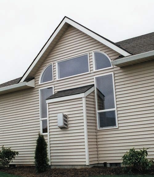
Chapter 40: Fireplace Construction and Layout                                                                                             915

                                                                   SPARK ARRESTER SCREEN                       CLAY FLUE LINER

                                                                                                               2" MORTAR CAP

                                                                   1 1/2" (40 mm) MIN.                       METAL FLASHING
                                                                   GROUT BTWN. 4" CMU
                                                                   & FLUE LINER                             CRICKET

                                                                   4" (100 mm) CMU IF
                                                                   LINED / 8" (200 mm)
                                                                   IF UNLINED

                                                                   VERT. STEEL REINFORCING                    STEEL ANCHOR STRAP
                                                                                                            2" MIN         HORIZ. STEEL
                                                                                                                           REINFORCING

                                                                                                                           MORTAR FILL
                                                                  SMOKE CHAMBER
                                                                                                                           DAMPER
                                                                   SMOKE SHELF
                                                                                                                           THROAT
                                                                   FIREBRICK LINER

                                                                                                                           LINTEL

                                                                                                                     26"
                                                                   ASH DUMP
                                                                                               8"     20"    18"
                                                                                                    MIN      MIN.
                                                                                                    .
FIGURE 403 Exterior view of a self-venting gas fireplace; it      CLEAN OUT
requires a vent similar to a dryer.

                                                                                    12"
terminates the gas supply to the fire if it senses a lack of
oxygen in the room.
   When working with factory-built fireplaces, several                                    6"                         4" (100 mm) MIN.
                                                                                                                     THICK HEARTH
items must be specified. The IRC requires the chimney
for direct- and top-vent fireplaces to conform to UL            FIGURE 404 Parts of a masonry fireplace and chimney.
standard 127. Factory-built fireplaces producing gases
with a temperature above 1000°F (540°C) at the chim-
ney entrance must meet UL 959. Although a section               occurs and will be explored shortly. The size of the
is not required, each of these chimney specifications           fireplace opening is important for the appearance and
should be provided on the floor plan or interior eleva-         operation of the fireplace. If the opening is too small,
tions, along with instructions to provide and install all       the fireplace will not produce a sufficient amount of
materials per the manufacturer’s specifications.                heat. If the opening is too large, the fire could make a
                                                                room too hot. Common design guidelines suggest that
                                                                the opening be approximately 1/30 of the room area
FIREPLACE TERMS
                                                                for small rooms, and 1/65 of the room area for large
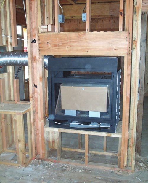
Fireplace construction has its own vocabulary, which            rooms. Table 40-1 shows suggested fireplace-opening
a drafter should know in order to draw a section.               sizes relative to the room size. The ideal dimensions for
Although some of these terms apply to prefabricated             a single-face fireplace have been determined to be 36"
fireplace units, they primarily relate to masonry fire-         (900 mm) wide and 26" (650 mm) high. These dimen-
places. Figure 40-4 shows the major components of a             sions may be varied slightly to meet the size of the brick
masonry fireplace and chimney. Terms are grouped by             or to fit other special dimensions of the room.
components in the firebox and the chimney to aid in                 The fireplace opening is the front of the firebox
learning their location and function.                           where the combustion of the fuel occurs. The opening
                                                                to the firebox may be on one, two, or three sides of the
                                                                fireplace. The more openings that are provided, the
Terms Related to the Firebox
                                                                more decorative and less efficient the unit becomes.
The fireplace opening is the area between the side and          Units can also be constructed so that the firebox is
top faces of the fireplace that serves as the front of the      covered with a hood allowing it to be totally open.
firebox. The firebox is the area where the combustion           Totally open fireplaces are typically used outside on
Fireplace Construction and Layout
916                                                                                                Architectural Drafting and Design

                               Suggested Width of Fireplace Openings Appropriate to Room Size

             SIZE OF ROOM                                 IF IN SHORT WALL                               IF IN LONG WALL

      (FT)            (MM)                              (IN.)          (MM)                             (IN.)         (MM)

  10 ⫻ 14         (3048 ⫻ 4267)                          24            (610)                           24–32        (610–813)

  12 ⫻ 16         (3658 ⫻ 4877)                         28–36         (711–914)                        32–36        (813–914)

  12 ⫻ 20         (3658 ⫻ 6096)                         32–36         (813–914)                        36–40        (914–1016)

  12 ⫻ 24         (3658 ⫻ 7315)                         32–36         (813–914)                        36–48        (914–1219)

  14 ⫻ 28         (4267 ⫻ 8534)                         32–40         (813–1016)                       40–48       (1016–1219)

  16 ⫻ 30         (4877 ⫻ 9144)                         36–40         (914–1016)                       48–60       (1219–1524)

  20 ⫻ 36         (6096 ⫻ 10 973)                       40–48       (1016–1219)                        48–72       (1219–1829)

TABLE 401 The Size of the Fireplace Should Be Proportioned to the Size of the Room (This will give both a pleasing appearance and
a fireplace that will provide sufficient heat without overheating the room.)

a patio or as a divider between rooms. For a fireplace              greater than 6 sq ft (0.557 m2), the hearth extension
with only one opening, the sides should be slanted                  must be increased to be 20" (500 mm) minimum with
slightly to radiate heat into the room. The rear wall               12" (300 mm) minimum side extensions. An ash dump
is inclined to provide an upward draft into the upper               is usually located in the inner hearth of a masonry
part of the fireplace and chimney. The firebox is usually           fireplace.
constructed of fire-resistant brick set in fire-resistant              The ash dump is an opening in the inner hearth into
mortar. Figure 40-5A and Figure 40-5B show mini-                    which ashes can be dumped. The ash dump is covered
mum wall thickness for the firebox and other fireplace              with a small metal plate, which can be removed to
components.                                                         provide access to the ash pit. The ash dump must be
    The minimum depth of the firebox is required                    located so that the ash removal will not create a hazard
to be 20" (500 mm). The firebox depth should be                     to combustible materials. The ash pit is the space below
proportional to the size of the fireplace opening.                  the fireplace where the ashes can be stored.
Providing a proper depth ensures that smoke will not                   The outer hearth may be made of any noncombus-
discolor the front face (breast) of the fireplace. With             tible material. The material is usually selected to blend
an opening of 36" × 26" (900 × 650 mm), a depth of 20"              with other interior design features and may be brick,
(500 mm) should be provided for a single-face fire-                 tile, marble, or stone. The outer hearth protects the
place. Table 40-2 lists recommended fireplace opening-              combustible floor around the fireplace.
to-depth proportions.                                                  Above the fireplace opening is a lintel. The lintel is
    The hearth is the floor of the firebox and con-                 a reinforced masonry or steel angle that supports the
sists of an inner and outer hearth. The inner hearth                masonry above the fireplace face. The minimum required
is the floor of the firebox. The hearth is made of                  bearing length for the lintel at each end of the fireplace is
fire-resistant brick and holds the burning fuel. The                4" (100 mm). The throat of a fireplace is the opening at
structural portion of the hearth must be made of 4"                 the top of the firebox that opens into the chimney. The
(100 mm) minimum reinforced masonry or concrete,                    throat must be at least 8" (203 mm) above the fireplace
but the portion that extends in front of the fireplace              opening and must be a minimum of 4" (100 mm) in
can be a minimum of 2" (50 mm) thick. The hearth                    depth. The cross-sectional area of the passageway above
is required to extend 16" (400 mm) in front of the                  the firebox, including the throat, damper, and smoke
fireplace opening and 8" (200 mm) beyond each side                  chamber, can’t be less than the cross-sectional area
of the fireplace. If the size of the fireplace opening is           of the flue. The throat should be closable when the
Fireplace Construction and Layout
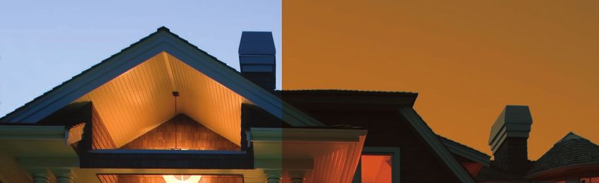
Chapter 40: Fireplace Construction and Layout                                                                                     917

                                                General Code Requirements

 ITEM                                              LETTER     UNIFORM BUILDING CODE* 1997

 Hearth Slab Thickness                             A          4”

 Hearth Slab Width                                 B          8” Fireplace opg. ⬍ 6 sq. ft.
   (Each side of opening)                                     12” Fireplace opg. ⱖ 6 sq. ft.

 Hearth Slab Length                                C          16” Fireplace opg. ⬍ 6 sq. ft.
   (Front of opening)                                         20” Fireplace opg. ⱖ 6 sq. ft.

 Hearth Slab Reinforcing                           D          Reinforced to carry its own weight and all imposed loads.

 Thickness of Wall or Firebox                      E          10” common brick or 8” where a fireback lining is used.
                                                              Jts. in fireback 1/4” max.

 Distance from Top of Opening to Throat            F          6”

 Smoke Chamber Edge of Shelf                       G
 Rear Wall—Thickness                                          6”
 Front & Side Wall—Thickness                                  8”

 Chimney                                           H          Four #4 full length bars for chimney up to 40” wide. Add two #4 bars
   Vertical Reinforcing                                       for each additional 40” or fraction of width or each additional flue.

 Horizontal Reinforcing                            J          1/4” ties at 18” and two ties at each bend in vertical steel.

 Bond Beams                                        K          No specified requirements.

 Fireplace Lintel                                  L          Noncombustible material.

 Walls with Flue Lining                            M          Solid masonry units or hollow masonry units grouted solid with at
                                                              least 4” nominal thickness.

 Walls with Unlined Flue                           N          8” solid masonry.

 Distance between Adjacent Flues                   O          4” including flue liner.

 Effective Flue Area                               P          See Figure 40–6.
 (Based on Area of Fireplace Opening)                         Verify with local code.

 Clearances                                        R          1” when outside of wall or 1/2” gypsum board.
   Wood Frame                                                 2” when entirely within structure.
   Combustible Material                                       6” min. to fireplace opening.
                                                              Combustible material within 12” (305 mm) of the fireplace opening
                                                              can’t extend more than 1/8” for each inch (3/25 mm) distance from
                                                              the opening.
   Above Roof                                                 2’ at 10’

 Anchorage                                         S
   Strap                                                      3/16” ⫻ 1”
   Number                                                     2
   Embedment into Chimney                                     12” hooked around outer bar w/6” ext.
 Fasten to                                                    4 joists
 Bolts                                                        Two 1/2” dia.

 Footing                                           T
   Thickness                                                  12” min.
   Width                                                      6” each side of fireplace wall.

 Outside Air Intake                                U          Optional

 Glass Screen Door                                            Optional

FIGURE 405A General code requirements for fireplace and chimney construction. The letters in the second column will be helpful in
locating specific items in Figure 40-5B.
Fireplace Construction and Layout
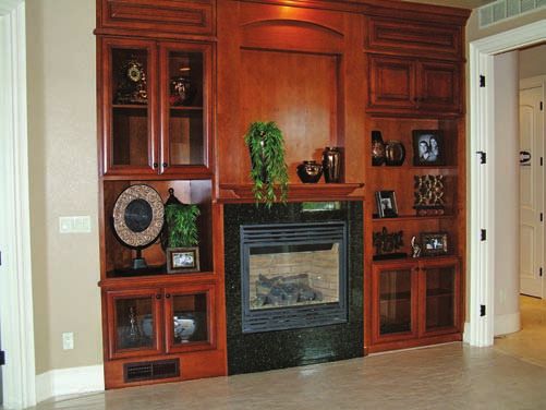
918                                                                                                                         Architectural Drafting and Design

                                                                                                                                 E
                                                                                                                BRICK                BLOCK

                                                    10'-0' MIN.
                                                   CLEARANCE                                                                 L
            MORTAR OR
            MASONRY CAP                                                   R

                                                       2'-0"
                                                       MIN.
                                                                                                           8"      WIDTH OF
                                                                                                                                             B
      K BOND BEAM                                                                                                 FIREPLACE
                                                                                                                   OPENING

                                                                                             10'-0' MIN.
          EFFECTIVE                               FLASHING
      P                                                                                       CLEARANCE
          FLUE AREA
                                                                                                                                                     MORTAR CAP
          HORIZONTAL                                                                     R

                                                                                                    MIN.
                                                                                                    2'-0"
      J
                                                                                                                                                      BOND BEAM
                                                                                                                                                 K
                                                                                                                                                 4" CMU

                                                                                                   FLASHING
                                                                   ANCHORAGE                                                                         EFFECTIVE
                                                          S                                                                                      P
            FLUE LINING                                                                                                                              FLUE AREA
                                                                                                                                        6"
                                                                                                                                        MIN.
                                                                                                                                                     HORIZONTAL
                                                                                                                                                 J
                                                                                                                                                     REINFORCING
          BOND BEAM
      K                                                                                                                                              TIES
                                                                                                                                                      BOND BEAM
     WALL THICKNESS                                                                                                                              K
   M                                                                                                                    R
     PARGE w/ MORTAR                                                              ANCHOR STRAP                                                   1 1/2" MIN.
   N                                                           R                                       S
                                                                                      FLUE LINER                                                 GROUT BTWN. 4"
                                                                                                                                                 CMU & CLAY
          VERTICAL                                                                                    4"                                         FLUE LINING
      H
          REINFORCING                                                                                 MIN.
                                                                    21" MINIMUM

                                                                                                                                                      SMOKE
                                                                      THERMAL
                                                                      DISTANCE

                                                   8" .                                               8"                                         G
                                                     IN                                                                                               CHAMBER
          SMOKE CHAMBER                            M
      G                                                                                               MIN.
                                                               F                                                                                      VERT. REINF.
                                                                                                                                                 H
                                                                                                                                                      20" LAP IF
                                                                                                      F                                               SPLICED TO
                                                                                                                                                      FTG. DOWELS
                                                                                             LINTEL
                                                                                                            L
                                                                                                   HEARTH
                                                               L
                                                                    32"

                                                                                                   EXTENSION
                                                                                                                                                     FIREBOX WALL
          FIREBOX WALL                  20"                                                             C                                        E
      E                                            C                                                                                                 THICKNESS
          THICKNESS                    MIN.
                                                                                                                                                      HEARTH SLAB
          HEARTH SLAB                                                                                                                            A
      A                                                                                                                                               THICKNESS
          THICKNESS
                                                                                                                                                 NATURAL GRADE
                                                                                         BARS IN
                                                                                         CONCRETE
             OPTIONAL                                                                                                                                    FOOTING
                                                                                         FOOTING                                                       T DEPTH
             CLEAN OUT                                           HEARTH SLAB
                                                               D
                                                                 REINFORCEMENT
                                       OPTIONAL
                                       ASH DUMP           4" (100mm) MIN.                             FOOTING WIDTH
                                                                                                                                                 T
                          T                               THICK HEARTH                                6" AROUND FREE
                                                                                                      STANDING FIREPLACE

                              BRICK FIREPLACE & CHIMNEY                             BRICK FIREPLACE / BLOCK CHIMNEY

FIGURE 405B Brick fireplace and chimney components. The circled letters refer to item references in Figure 40-5A.

fireplace is not in use. The flow of air through the fire-
place throat is controlled by a damper. The damper
                                                                                  Chimney Terms
must be made of ferrous metal that extends the full                               The smoke chamber acts as a funnel between the fire-
width of the throat to prevent heat from escaping up                              box and the chimney. The shape of the smoke chamber
the chimney when the fireplace is not in use. When                                should be symmetrical so that the chimney draft pulls
fuel is being burned in the firebox, the damper can be                            evenly and creates an even fire in the firebox. The smoke
opened from inside the room that contains the fireplace                           chamber should be centered under the flue in the
to allow smoke from the firebox into the smoke cham-                              chimney and directly above the firebox. The overall
ber of the chimney.                                                               size of the smoke chamber is regulated by the IRC.
Chapter 40: Fireplace Construction and Layout                                                                             919

                                           Width of                Height of                   Depth of
                                           Opening (W)             Opening (H)                 Opening (D)

              FIREPLACE
                 TYPE                   (IN.)      (MM)         (IN.)        (MM)          (IN.)         (MM)
               Single face               28         700          24           600            20           500
                                         30         760          24           600            20           500
                                         30         760          26           660            20           500
                                         36         900          26           660            20           500
                                         36         900          28           700            22           560
                                         40        1000          28           700            22           560
                                         48        1200          32           800            25           635
               Two faces                 34         865          27           685            23           585
               adjacent ”L”              39         990          27           685            23           585
               or corner type            46        1170          27           685            23           585
                                         52        1320          30           760            27           635
               Two faces*                32         800          21           530            30           760
               opposite                  35         890          21           530            30           760
               look-through              42        1070          21           530            30           760
                                         48        1200          21           530            34           865
               Three face*               39         990          21           530            30           760
               2 long, 1 short           46        1170          21           530            30           760
               3-way opening             52        1320          21           530            34           865
               Three face*               43        1090          27           685            23           585
               1 long, 2 short           50        1270          27           685            23           585
               3-way opening             56        1420          30           760            27           686
             *Fireplaces open on more than front and one end are not recommended.
             TABLE 402 Guide for Fireplace Opening-to-Depth Proportions

The inside height of the chamber can’t be greater than               The chimney is the upper extension of the fireplace
the inside width of the fireplace opening. The walls of the      and is built to carry off the smoke from the fire. The
smoke chamber must be made of solid masonry units,               main components of the chimney are the flue, lining,
stone, concrete, or hollow masonry units that have been          anchors, cap, and spark arrester. The wall thickness
filled with grout. The material is corbelled to form the         of the chimney will be determined by the type of flue
tapered shape, but the IRC requires that the interior            construction. Masonry chimneys are not allowed to
surface of the masonry units should not be exposed               change in size or shape within 6" (150 mm) above or
to the smoke chamber. The walls of the smoke cham-               below any combustible floor, ceiling, or roof compo-
ber can’t be greater than 30° when formed from cor-              nent penetrated by the chimney. Figure 40-5A shows
belled masonry units, but can be inclined up to 45°              the minimum wall thickness for chimneys.
if prefabricated linings are used. If the walls of the               The flue is the opening inside the chimney that
chamber are made with a lining of 2" (50 mm) fire-               allows smoke and combustion gases to pass from the
brick or of 5/8" (16 mm) vitrified clay, each of the four        firebox away from the structure. A flue may be con-
chamber walls must have a minimum thickness of 6"                structed of normal masonry products or may be covered
(150 mm), including the liner. If no lining is provided,         with a flue liner. The size of the flue must be propor-
the four chamber walls must each be a minimum of 8"              tional to the size of the firebox opening and the number
(200 mm) thick. A smoke shelf is located at the bottom           of open faces of the fireplace. A flue that is too small will
of the smoke chamber behind the damper. The smoke                not allow the fire to burn well and will cause smoke to
shelf prevents downdrafts from the chimney entering              exit through the front of the firebox. A flue that is too
the firebox.                                                     large for the firebox will cause too great a draft through
920                                                                                                                                               Architectural Drafting and Design

                                                                                                                                                           3000

                                                                                                                                                           2800

                                                                                                                                                           2600

                                                                                                                                                           2400

                         MIN. CROSS-SECTIONAL AREA (SQ. IN.)   224          269                                                                            2200

                                                                                                                                                           2000

                                                               187          214                                                                            1800

                                                                                                                                                           1600

                                                               140          168                                                                            1400

                                                                                                                                                           1200
                                                               110          124
                                                                                                                                                           1000

                                                                76            91                                                                           800

                                                                70            82                                                                           600
                                                                53            58
                                                                                                                                                           400
                                                                32            37
                                                                                                                                                           200
                                                                       RECTANGULAR

                                                                                                                                                       OPENING AREA
                                                                                     13   14   15   16   17   18    19   20   21   22   23   24   25
                                                                        SQUARE OR

                                                                                                                                                        FIREPLACE

                                                                                                                                                          (SQ. IN.)
                                                               ROUND

                                                                                                     HEIGHT, MEASURED FROM FLOOR
                                                                          FLUES
                                                               FLUES

                                                                                                      OF COMBUSTION CHAMBER TO
                                                                                                            TOP OF FLUE (FT.)

                         FOR SI: 1 foot = 304.8 mm, 1 square inch = 645.16 mm2.

                      FIGURE 406 Flue sizes for masonry chimneys based on the IRC. Courtesy 2009 International
                      Residential Code, Copyright © 2009, Washington, DC. International Code Council. Reproduced with
                      permission. All rights reserved. www.iccsafe.org.

the house as the fire draws its combustion air. Flue sizes                                                         The masonry cap is built so that openings allow for the
are generally required to equal either 1/8 or 1/10 of the                                                          prevailing wind to blow through the hood and create
fireplace opening. Figure 40-6 shows required flue sizes                                                           a draft in the flue. The metal hood can be rotated by
based on the IRC. Figure 40-7 shows recommended                                                                    wind pressure to keep the opening of the hood down-
areas for residential fireplaces based on the size and                                                             wind and thus prevent rain or snow from entering the
number of openings.                                                                                                flue. A spark arrester is a screen placed at the top of
    A chimney liner is usually built of fire clay or terra-                                                        the flue inside the hood to prevent combustibles from
cotta. The liner is built into the chimney to provide                                                              leaving the flue.
a smooth surface to the flue wall and to reduce the
width of the chimney wall. The smooth surface of the                                                               Chimney Reinforcement
liner will help reduce the buildup of soot, which could                                                            In areas subject to seismic damage, a minimum of
cause a chimney fire. The chimney cap is the sloping                                                               four vertical reinforcing bars 1/2" (13 mm) in diam-
surface on the top of the chimney. The slope pre-                                                                  eter (#4) must be used in the chimney, extending
vents rain from collecting on the top of the chimney.                                                              from the foundation up to the top of the chimney.
The flue normally projects 2" to 3" (50 to 75 mm)                                                                  These vertical bars are supported at 18" (450 mm)
above the cap so that water will not run down the                                                                  intervals with a 1/4" (6 mm) horizontal rebar. Two
flue. The chimney hood is a covering that may be                                                                   additional #4 bars are required for each additional
placed over the flue for protection from the elements.                                                             40" (1000 mm) of width, or fraction thereof, or for
The hood can be made of either masonry or metal.                                                                   each additional flue that is added to the chimney.
Chapter 40: Fireplace Construction and Layout                                                                                                         921

                                                                            AREA OF FIRE-             FLUE SIZE
                            WIDTH OF        HEIGHT OF       DEPTH OF       PLACE OPENING           REQUIRED AT 1/10                FLUE SIZE
                            OPENING         OPENING         OPENING           FOR FLUE                 AREA OF                 REQUIRED AT 1/8
        TYPE OF                 W               H               D          DETERMINATION              FIREPLACE                    AREA OF
       FIREPLACE               IN.             IN.             IN.             SQ IN.                 OPENING                FIREPLACE OPENING

                                28               24              20               672                 8 1/2 ⫻ 13                   8 1/2 ⫻ 17
                                30               24              20               720                 8 1/2 ⫻ 17                    13” round
                                30               26              20               780                 8 1/2 ⫻ 17                    10 ⫻ 18
                                36               26              20               936                    10 ⫻ 18                    13 ⫻ 17
                                36               28              22               1008                   10 ⫻ 18                    10 ⫻ 21
                                40               28              22               1120                   10 ⫻ 18                    10 ⫻ 21
                                48               32              25               1536                   13 ⫻ 21                    10 ⫻ 21
                                60               32              25               1920                   17 ⫻ 21                    21 ⫻ 21
                                34               27              23               1107                   10   ⫻   18                10   ⫻   21
                                39               27              23               1223                   10   ⫻   21                13   ⫻   21
                                46               27              23               1388                   10   ⫻   21                13   ⫻   21
                                52               30              27               1884                   13   ⫻   21                17   ⫻   21
                                64               30              27               2085                   17   ⫻   21                21   ⫻   21

                                32               21              30               1344             13 ⫻ 17 or 10 ⫻ 21         17 ⫻ 17 or 13 ⫻ 21
                                35               21              30               1470             17 ⫻ 17 or 13 ⫻ 21              17 ⫻ 21
                                42               21              30               1764                  17 ⫻ 21                    17 ⫻ 21
                                48               21              34               2016                  17 ⫻ 21                    21 ⫻ 21

                                39               21              30               1638             13 ⫻ 21 or 17 ⫻ 17               17 ⫻ 21
                                46               21              30               1932                  17 ⫻ 21                     21 ⫻ 21
                                52               21              34               2184                  17 ⫻ 21                     21 ⫻ 21

                                43               27              23               1782             13 ⫻ 21 or 17 ⫻ 17              17 ⫻ 21
                                50               27              23               1971                  17 ⫻ 21                    17 ⫻ 21
                                56               30              27               2490                  21 ⫻ 21                   21 ⫻ 21 or
                                68               30              27               2850                13 ⫻ 21 & 䊱               2—1 0 ⫻ 21 䊱
                                                                                                        10 ⫻ 21                 2—1 3 ⫻ 21 or
                                                                                                                               2—1 7 ⫻ 17 or 䊱
                                                                                                                              10 ⫻ 18 & 17 ⫻ 21

䊱 Rather than using two flue liners in chimney, the flue is often left unlined with 8˝ masonry walls. Unlined flues must have a minimum area of 1/8
fireplace opening.
FIGURE 407 Recommended flue areas for residential fireplaces.

Two #4 rebar are also installed when the vertical steel                        DRAWING THE FIREPLACE SECTION
is bent for a change in chimney width. In addition to
the reinforcement in the chimney, the chimney must                             The section for a masonry fireplace can be a valuable part
be attached to the structure in some seismic areas.                            of the working drawings. Although a fireplace drawing
This is done with steel anchors that connect the                               is required by most building departments when a home
fireplace to the framing members at each floor and                             has a masonry fireplace and chimney, a drafter may not
ceiling level that is more than 6' (1800 mm) above                             be required to draw a fireplace section. Because of the
the ground. Two 3/16" × 1" (5 × 25 mm) steel straps                            similarities of fireplace design, a fireplace drawing is
must be embedded 12" (300 mm) minimum into the                                 often kept on file as a stock detail at many offices. When
chimney, and they must be hooked around the outer                              a house that has a fireplace is being drawn, the drafter
steel rebar and extend 6" (150 mm) beyond the                                  needs only to get the stock detail from a file, make the
bend. The straps must attach to four floor or ceiling                          needed copies, and attach them to the prints of the plans.
joists with two 1/2" (13 mm) bolts. These straps can                           If the drafter is using AutoCAD, the stock drawing can
be omitted if the chimney is built completely within                           be inserted into the working drawings. A stock detail can
the exterior walls.                                                            be seen at the end of the chapter.
922
                                                       GOING
                                                       GREEN
                                       Goals of an Energy-Efficient Fireplace

INTRODUCTION                                                    expelled up the chimney after combustion. As the air is
Heating and air quality are major considerations in gaining     expelled after combustion, new air must be drawn into
LEED credits. A standard fireplace will provide very little     the fire. If the air for combustion is taken from the room
assistance in heating a home or in gaining LEED credits         being heated, a draft will be created. To reduce drafts
in the categories of Indoor Environmental Quality or            and maximize the heat produced by the fire, combustion
Energy Atmosphere. To greatly increase the efficiency of        air must be taken from an outside source or from spaces
a masonry fireplace, add glass doors, ductwork that will        in the residence that are ventilated with outside air such
circulate the heated air through the lower portion of the       as non-mechanically-ventilated crawl or attic spaces. The
chimney, and mechanical blowers. Using a UL-approved            restrictions by the IRC specify that the exterior air intake
cast-iron stove or heating unit will add to the efficiency      can’t be located in a basement or garage, and the air
and may qualify for LEED credits. Materials listed in CSI       intake can’t be placed at an elevation higher than the
Division 10.35 can be used to provide supplemental heat         firebox. When the floor plan was completed, a note was
to a residence. The efficiency of the heating unit will also    placed on the plan reading:
depend on the choice of fuel. Common fuels include
wood, gas, and pellets.                                            Provide a Screened, Closable Vent Within 24"
                                                                   Of the Firebox.

Choosing Fuels                                                     Providing the note on the floor plan will help ensure
Burning wood to produce heat creates significant pollution;     that a draft is not created. As the fireplace section
emissions of particulates, carbon monoxide, VOCs, and           is drawn, the vent for air intake should be indicated.
methane are significantly greater from wood stoves than         The vent should be placed on an exterior wall or
from any other common heating fuel. If sustainable wood         in the back of the fireplace in a position that is high
is locally available, using it as a fuel has no net impact on   enough above the ground so that it will not be blocked
global warming. Burning wood from sustainable forest            by snow. Combustion kits are available that can be
compensates for the carbon emissions caused from                installed in the duct, to heat the outside air before it
combustion. If wood is burned in an efficient cast-iron stove   enters the firebox. Another alternative to drawing air
or fireplace that minimizes pollution, it can be a good fuel    from the outside is to draw combustion air from the
choice. Products such as pellets or natural gas have superior   cold-air return ducts of the heating system. The HVAC
burning efficiencies and reduced particulate emissions in       contractor can calculate the needed size and provide
comparison to even the best wood stoves. Multi-fuel stoves      a duct that takes the necessary cool air from inside the
have the capacity to efficiently burn pellets or other solid    home to supply the fireplace.
fuels such as wood, corn, or coal. However, combustion
in interior spaces, particularly in a tight house, can be an    Using the Heated Air Efficiently
indoor air-quality concern due to leakage of flue gases and     Once the fire has heated the air in the firebox, that air
particulates. New wood stoves are much more efficient than      must be used efficiently to heat the structure. Chapter 12
old ones, but pellet stoves are less polluting than even the    introduced passive solar heating and the use of a
best EPA-certified wood stoves.                                 masonry mass to store heat. A masonry fireplace and
                                                                chimney will provide mass to absorb, store, and radiate
Providing Air Supply                                            the heat back into the room long after the fire is out.
In addition to adding charm and elegance to a room, a           When a fireplace is built on an outer wall, the mass of
fireplace also needs to be functional. No matter what the       the fireplace is often outside the structure, to increase
material is, consideration must be given to the air that        the usable floor space. With the chimney outside the
will be used by the fireplace. Three points to consider are     structure, the interior face of the fireplace is the only
how air will be supplied to the fire, how to use the heated     surface that radiates heat back into the room. The
air created by the fire, and how to minimize heated air         amount of heat radiated into a room is increased as
escaping through the chimney.                                   more of the fireplace and chimney mass is located inside
    Introduced in Chapter 12 and Chapter 27, newer              the structure. Placing the fireplace and chimney totally
construction methods can greatly reduce the amount of           within a structure will allow all surfaces of the masonry
air that enters the structure. When a fireplace is added to     to radiate heat into the structure.
a relatively airtight residence, the fireplace can actually        Altering the shape of the firebox will also increase
cool a room if proper precautions are not taken. Air must       the amount of air radiated back to the room. Table 40-1
be provided to the fireplace for combustion, and air is         shows common sizes of fireplace openings. Increasing
923
                                                     GOING
                                                     GREEN
                              Goals of an Energy-Efficient Fireplace (Continued)

the width and height of the opening and decreasing
the depth of the fireplace will increase the amount of                                           DECREASED              20"
heat in the room. This altered firebox shape is based on                                         DEPTH
                                                                                                 12" MIN.
the Rumford design that was popular through the mid-
1800s. It has been reinvented and has become popular in
many areas, and is now permitted by the IRC. Increasing
the length of the sidewalls and decreasing the length

                                                                 INCREASED
                                                                             ANGLE
of the rear walls will also increase the heat returned to
the room. Figure 40-8 shows the difference between a
Rumford-type firebox and traditional designs. A third
method of increasing the heat returned to the room is a
mechanical blower.

Decreasing Chimney Heat Loss
The traditional means of reducing heat loss up the
chimney has been a damper. The damper is opened
while the fire is burning and closed when the fire is out.

                                                                                     INCREASED
                                                                                       HEIGHT
Because the damper is not airtight, warm air from the

                                                                                                         32" TYP.
room will rise and be drawn up the chimney. As the air in
the chimney cools, it will start a reverse current, drawing
cold air into the heated room. Placing a chimney on
an outer wall will increase this tendency, because the
chimney will be cooler. In very cold climates, the reverse                           RUMFORD FIREBOX            TYPICAL FIREBOX
convection current can be reduced by an additional
damper at the top of the chimney.                             FIGURE 408 Comparison of a Rumford-style firebox and
                                                              traditional construction. The Rumford style, popular through
                                                              the mid-1800s, has been reinvented to increase the amount
                                                              of heated air that is returned to the room containing the
                                                              fireplace.

   If you are required to draw a fireplace section, a print   STEP 3 Lay out the foundation for the fireplace. The
of the floor plans will be needed to help determine wall        footing must be 6" (150 mm) wider on each side
locations and the size of the fireplace. As the drawing         than the fireplace and 12" (300 mm) deep.
for the fireplace is started, use construction lines. See     STEP 4 Lay out the hearth to be 16" (400 mm) in front
Figure 40-9 for Step 1 through Step 4.                          of the fireplace. The hearth will vary in thickness,
                                                                depending on the type of finishing material used. If
                                                                the fireplace is being drawn for a house with a wood
Layout of the Fireplace                                         floor, the hearth will require a 4" (100 mm) mini-
                                                                mum concrete slab projecting from the fireplace base
STEP 1 Lay out the width of the fireplace: 20" (500 mm)
                                                                to support the finished hearth.
  for the firebox and 8" (200 mm) for the rear wall.
                                                                 See Figure 40-10 for Step 5 through Step 8.
STEP 2Lay out all walls, floors, and ceilings that are
  near the fireplace. Be sure to maintain the required        STEP 5 Lay out the firebox. Assume that a 36" × 26" × 20"
  minimum distance from the masonry to the wood as               (900 × 650 × 500 mm) firebox will be used. See
  determined by the code in your area.                           Figure 40-11 for guidelines for laying out the firebox.
924                                                                                           Architectural Drafting and Design

                                                                                                          STEP 8

                                              STEP 2
                                                                                                           STEP 7

                                              STEP 2

                                             STEP 1
                                                                STEP 6
                                                                (STEP 6 REQUIRES
                                                                NO DRAWING. SEE
                                                                FIGURE 40.12 TO
                                                                DETERMINE THE                              STEP 5
                                                                FLUE SIZE.)
      STEP 4
                                             STEP 2

                                              STEP 3

FIGURE 409 Fireplace layout using construction lines.     FIGURE 4010 Layout of the firebox and flue using construc-
                                                           tion lines.

STEP 6  Determine the size of flue required. A 36" × 26"
   (900 × 650 mm) opening has an area of 936 sq in.                                     60˚            4" MIN. W/
                                                                                                       LINER 100 mm
   By examining Figure 40-12 you can see that a flue
   with an area of 91 sq in. is required. The flue walls
                                                                                                          4"
   can be constructed using either 8" (200 mm) of                                                        100 mm
                                                                  200 mm

   masonry or 4" (100 mm) of masonry and a clay flue
   liner. If a liner is used, a 13" (325 mm) round liner
                                                                  8"

   is the minimum size required.
STEP 7  Lay out the flue with a liner. Draw the inte-                                                     4" FIREBRICK
                                                                                    4"
   rior face of the liner. The thickness will be shown                                                   100 mm
                                                                  26" TYP.
                                                                  650 mm

                                                                                   100 mm
   later.
STEP 8  Determine the height of the chimney. The IRC                                20" MIN.              4"
                                                                                    500 mm               100 mm
   requires the chimney to project 2' (600 mm) mini-
   mum above any construction within 10' (3000 mm)
   of the chimney (see Figure 40-13).

                                                           FIGURE 4011 Minimum sizes required for firebox layout.
Chapter 40: Fireplace Construction and Layout                                                                                                                                            925

                                                                         48

                                                                         46

                                                                          21
                                                                                                               1 :1

                                                                             "x

                                                                             FL
                                                                         44

                                                                                U E 69
                                                                                 21
                                                                                  17

                                                                                    "

                                                                                    SI
                                 HEIGHT OF FIREPLACE OPENING (INCHES)

                                                                                      "x
                                                                         42

                                                                                      (2
                                                                                       13

                                                                                       Z E Q. I
                                                                                          21
                                                                                          "x

                                                                                            S
                                                                                             "(
                                                                         40

                                                                                             17

                                                                                              21

                                                                                                22
                                                                                                 "x
                                                                                                 1 0"

                                                                                                 " (1

                                                                                                  N.
                                                                                                   3
                                                                         38

                                                                                                     )
                                                                                                     SQ
                                                                                                       1 0"

                                                                                                       1

                                                                                                       73

                                                                                                                                        2
                                                                                                         7"
                                                                                                         x1

                                                                                                                                      1/
                                                                                                          .I
                                                                                                            SQ
                                                                                                            (

                                                                                                             N.
                                                                                                             x2

                                                                                                                                    1
                                                                                                              1
                                                                                                              8" (
                                                                         36

                                                                                                                                  1:
                                                                                                                71

                                                                                                                )
                                                                                                                  . IN
                                                                                                                   1"

                                                                                                                                                                 )
                                                                                                                    13 "

                                                                                                                                                                O
                                                                                                                     112

                                                                                                                     SQ
                                                                                                                      13

                                                                                                                                                              TI
                                                                                                                       .)
                                                                                                                       (1 3

                                                                                                                                                            RA
                                                                                                                                              4
                                                                         34

                                                                                                                          "x

                                                                                                                          .

                                                                                                                                            3/
                                                                                                                           RO

                                                                                                                            SQ

                                                                                                                            IN
                                                                                                                            8

                                                                                                                                                       TH
                                                                               81

                                                                                                                                          1
                                                                                                                              17

                                                                                                                              SQ

                                                                                                                               .)

                                                                                                                                        1:
                                                                                                                                UN

                                                                                                                                                     ID
                                                                                                                                 . IN
                                                                         32
                                                                                   /2"

                                                                                                                                   "(

                                                                                                                                                    W
                                                                                                                                    . IN
                                                                                                                                      D(

                                                                                                                                      13
                                                                                                                                       .)

                                                                                                                                                TO
                                                                                                                                          x1

                                                                                                                                          .
                                                                                                                                            4S

                                                                                                                                            )
                                                                                                                                            91
                                                                         30

                                                                                                                                            T
                                                                                                                                           H
                                                                                                                                              7"

                                                                                                                                               Q.
                                                                                                                                               SQ

                                                                                                                                          G
                                                                                                                                                81

                                                                                                                                        EI
                                                                                                                                                  (8 7

                                                                                                                                                   IN
                                                                         28

                                                                                                                                      (H
                                                                                                                                                    . IN

                                                                                                                                                      .)
                                                                                                                                                      ( 69
                                                                                                                                                       /2 " . I N . )

                                                                                                                                    2
                                                                                                                                                         S

                                                                                                                                  1:
                                                                                                                                                          .)
                                                                                                                                                           Q.
                                                                                                                                                             SQ
                                                                                                                                                             x1

                                                                         26
                                                                                                                                                              I N.
                                                                                                                                                                 3"

                                                                                                                                                                  )

                                                                         24
                                                                              24     28    32     38   40    44   48   52   56    60                      64     68       72
                                                                                                  WIDTH OF FIREPLACE OPENING (INCHES)
                                                                        GRAPH TO DETERMINE THE PROPER FLUE SIZE FOR A SINGLE-FACE FIREPLACE, BY
                                                                        MATCHING THE WIDTH AND HEIGHT OF THE FIREPLACE OPENING, THE MINIMUM
                                                                        FLUE SIZE CAN BE DETERMINED. ONCE THE MINIMUM FLUE SIZE HAS BEEN
                                                                        DETERMINED, THE CHIMNEY SIZE CAN BE DETERMINED.

                               Nominal                                                    Actual Outside                 Effective       Max. Area of          Minimum Outside
                               Dimension of                                               Dimensions of                    Flue           Fireplace              Dimension of
                               Flue Lining                                                 Flue Lining                     Area           Opening                  Chimney

                              8 1/2" Round                                                8 1/2" Round                 39 sq. in.         390 sq. in.                   17" x 17"
                              8 1/2" x 13" oval                                           8 1/2" x 12 3/4"             69 sq. in.         690 sq. in.                   17" x 21"
                              8 1/2" x 17" oval                                           8 1/2" x 16 3/4"             87 sq. in.         870 sq. in.                   17" x 25"
                              13" Round                                                   12 3/4" Round                91 sq. in.         1092 sq. in.                  21" x 21"
                              10" x 18" oval                                              10" x 17 3/4"                112 sq. in.        1120 sq. in.                  19" x 26"
                              10" x 21" oval                                              10" x 21"                    138 sq. in.        1380 sq. in.                  19" x 30"
                              13" x 17" oval                                              12 3/4" x 16 3/4"            134 sq. in.        1340 sq. in.                  21" x 25"
                              13" x 21" oval                                              12 3/4" x 21"                173 sq. in.        1730 sq. in.                  21" x 30"
                              17" x 17" oval                                              16 3/4" x 16 3/4"            171 sq. in.        1710 sq. in.                  25" x 25"
                              17" x 21" oval                                              16 3/4" x 21"                223 sq. in.        2230 sq. in.                  25" x 30"
                              21" x 21" oval                                              21" x 21"                    269 sq. in.        2690 sq. in.                  30" x 30"

                           FIGURE 4012 Common flue and chimney sizes based on the area of the fire-
                           place opening.

                                 10' - 0"
                                                                                                                                Drawing with Finished-Quality Lines
                                                                                                                                STEP 9   Use bold lines to outline all framing materials, as
                                                                                                                                      shown in Figure 40-14.
                                                                        MIN.
                                                                        2'-0"

                                                                                                                                STEP 10    Use bold lines to outline the masonry, flue liner,
                                                                                                                                      and hearth.
                                                                                                                                STEP 11   Use thin lines at a 45° angle to crosshatch the
                                                                                                                                      masonry.
                                                                                                                                STEP 12    Crosshatch the firebrick with lines at a 45° angle
                                                                                                                                      so that a grid is created (Figure 40-15).
                                                                                                                                STEP 13     Draw all reinforcing steel with bold lines.
                                                                                                                                      Check local building codes to determine what steel
                                                                                                                                      will be required.
FIGURE 4013 The chimney is required to extend 2' (600 mm)
above any part of the structure that is within 10’ (3000 mm).                                                                   STEP 14         Draw the lintel with a very bold line.
926                                                                                        Architectural Drafting and Design

                                                                  STEP 10

                                           STEP 9

                                                                  STEP 11

                                          STEP 9

                                                                   STEP 12

FIGURE 4014 Draw all framing members with finished-quality   FIGURE 4015 Darken all masonry materials.
lines.

STEP 15Draw the damper with a very bold line                            SECTION—MASONRY
  (Figure 40-16).                                                       FIREPLACE CHECKLIST
      Dimension the drawing. Items that must be
STEP 16                                                                 Plot this section and any required details
  dimensioned include the following:                          using an appropriate scale on size D material and place
  A.   Height above roof.                                     with other sections.
                                                                 Use stock details from Chapter 38 to complete the
  B.   Width of hearth.                                       section showing.
  C.   Width and height of firebox.
  D.   Width and depth of footings.
                                                              Plot
  E.   Wood-to-masonry clearance.
                                                              ❑ Assume a scale 3/8" = 1'−0" minimum unless your
STEP 17 Place notes on the drawing using Figure 40-17 as        instructor provides other instructions.
  a guide. Notes will vary, depending on the code that
  you follow and the structural material that has been        ❑ Text: Assume all text to be 1/8" high, neatly aligned
  specified on the floor, framing, and foundation plans.        in columns.
Chapter 40: Fireplace Construction and Layout                                                                                                  927

                                                                                                                        2" MORTAR CAP

                                                              CHIMNEY TO EXTEND
                                                              2'-0" ABOVE HIGHEST                                     (2) #4Ø BOND BM.
                                                              POINT OF BUILDING
                                                              WITHIN 10'-0"                                             26 GA. FLASH.

                                                                                                                 STD. TRUSSES @
                                                                                                                     24" O.C.

     STEP 13                                                   3/16" X 1" STRAP
                                                               OVER 4 TRUSSES
                                                               MIN. W/ (2) 1/2" DIA.                                      (4) #4Ø/40" WIDTH
                                                               LAGS EA. END                                               W/ (2) #4 EA. ADD.
                                                                                                                          40" / FLUE.
                                                                        1" MIN. CLR.
                                                                                                                        # 4Ø @ 18" O.C. MAX.
                                                               (2) 3/16" X 1" STRAPS
                                                               EMBEDDED 12" MIN.
                                                               INTO CHIMNEY &                                             CLAY FLUE LINER
    STEP 13                                                    HOOKED AROUND
                                                               OUTER BAR W/ 6"
                                                               MIN. BEND. FASTEN
                                                               TO 4 JST. MIN W/ (2)
                                                               1/2" M.B MIN.

                                                                    SOLID BLK. FOR                                    (2) #4 TIES @ EA.
                                                                    ANCHORAGE                                         FLOOR, CEIL, ROOF
                                                                      4 X 12 HDR.                                     & EA. BEND IN VERT.
                                                                                                                       REBAR.
     STEP 15                                                                                                            #4 TIES @ 18" O.C.
                                                                    21" MINIMUM
                                                                                               8
                                                                                              MI "                        PARGED SMOKE
                                                                                    8" MIN.
                                                                                                N.
                                                                                                                          SHELF
     STEP 14
                                                                                                                      C. I. DAMPER

                                                                                                                        FIREBRICK LINER
                                                                       4"X 3"X 3/16" LINTEL
                                                                     26"

                                                                                              16"    20"      8" MIN.
     STEP 13                                                                                  MIN.   MIN.
                                                                   C. T. HEARTH

                                                                                  2"MIN.
                                                                                  CLR.
FIGURE 4016 Draw all reinforcing steel.
                                                                                                                              1'-0"
                                                                                                                     3"

                                                               4" MIN. THICK
❑ Titles: Assume to be 1/4" high text minimum.                 HEARTH
                                                                                                     8"         6"
                                                               (4) #4 EA. WAY
❑ Leader length/Leader location: Center of top line on                                                3'-8"

  left/center of bottom line on right.                      FIREPLACE SECTION
❑ Insert drawings into a drawing sheet with a com-          1/2"     =             1' - 0"

  pleted title block.
                                                          FIGURE 4017 Place the notes and dimensions.
❑ Freeze viewports.

Drawing                                                     ❑ Show required beams and girders for construction
❑ Show the required material to construct the fireplace       of roof, walls, and floor systems.
  and chimney including:                                    ❑ Spark arresters or chimney caps.
  ❑ Coordination with floor plan representation.            ❑ Flue lines and chimney materials.
  ❑ Wall construction surrounding the chimney.              ❑ Chimney reinforcement.
  ❑ Floor/foundation support that matches the foun-         ❑ Headers, required metal hangers, and required
    dation plan.                                              blocking.
928                                                                                    Architectural Drafting and Design

  ❑ Firebox/combustion chamber construction.
  ❑ Smoke shelf, damper, lintel, firebrick.
  ❑ Hearth including ash dump, and cleanout.                                                            STEP 1

                                                                                                           STEP 2
Annotation
❑ Specify all materials including:
                                                                   STEP 2
  ❑ Spark arresters or chimney caps.                                                                     STEP 4
                                                                  STEP 1
  ❑ Flue lines and chimney materials.                                                                    STEP 3

  ❑ Chimney reinforcement.
  ❑ Headers, required metal hangers.                     FIGURE 4018 Fireplace elevation layout.
  ❑ Firebox/combustion chamber materials.
  ❑ Smoke shelf, damper, lintel, firebrick thickness.
  ❑ Hearth material, ash dump size, and cleanout size.   Elevation Layout
                                                         STEP 1  Lay out the size of the wall that will contain the
Dimensions                                                  fireplace.
❑ Floor to ceiling heights.                              STEP 2   Lay out the width of the chimney.
❑ Firebox opening height.                                STEP 3  Lay out the height and width of the hearth if a
                                                            raised hearth is to be used.
❑ Firebox depth.
                                                         STEP 4   Lay out the fireplace opening.
❑ Hearth extension in front of firebox.
❑ Height of hearth above the finish floor.
❑ Thickness of hearth is cantilevered.                   Finished-Quality Lines
❑ Throat clearance.                                      Usually the designer will provide the drafter with a
                                                         rough sketch similar to Figure 40-19 to describe the
❑ Chimney height above roof 10' / 2' minimum.
                                                         finishing materials on the face of the fireplace. By using
❑ 2" clearance of chimney/wood framing at roof/wall      this sketch and the methods described in Chapter 24,
  and wood floor assemblies.                             the fireplace elevation can be drawn (see Figure 40-20).
❑ Foundation size/depth and 6" minimum extension         Once the finishing materials have been drawn, the eleva-
  beyond chimney.                                        tion can be lettered and dimensioned as in Figure 40-21.
                                                         Notes will need to be placed on the drawing to describe
                                                         all materials. Dimensions will be required to describe:
FIREPLACE ELEVATIONS
                                                         1. Room height.
The fireplace elevation is the drawing of the fire-
place as viewed from inside the home. Fireplace          2. Hearth height.
elevations typically show the size of the firebox and    3. Fireplace opening height and width.
the material that will be used to decorate the face of   4. Mantel height.
the fireplace. Fireplace elevations can be drawn by
using the following steps. See Figure 40-18 for Step 1
through Step 4.
Chapter 40: Fireplace Construction and Layout                                                                                                                   929

                FIGURE 4019 The drafter can often use the designer’s preliminary sketch as a guide when drawing
                the finishing materials for a fireplace elevation.

                                                                                                  RECESS THIS AREA
                                                                              8"   2'-0"          4" MIN.                    3'-0"    1'-0"

                                                                                                                                                 MIRROR
                                                                                                                                                 BY OWNER

                                                                                                                                                 4 X 12 OAK
                                                                                                                                                 MANTEL

                                                                                                                                              1'-0"
                                                                                                                                                      OPEN TO
                                                                                                                                                      DINING
                                                                                                                                                      ROOM

                                                                                                                                              4'-6"
                                                                      3'-6"

                                                                                                                     2'-2"

                                                                                                                              3'-0"

                                                                                                                     LINE OF HEARTH
FIGURE 4020 Drawing the elevation with finished line                                USED BRICK
                                                                                                               JUMBO PAVERS ON EDGE
quality.
                                                                                     LIVING ROOM
                                                                                    1/2"           1'-0"

                                                                   FIGURE 4021 Lettering and dimensions for a fireplace
                                                                   elevation.
930                                                                                                                              Architectural Drafting and Design

CADD APPLICATIONS
Drawing Fireplace Sections and Elevations with CADD

INTRODUCTION                                                                          be used to organize materials. Once all objects have been
By following the steps that were provided for drawing                                 assigned to the desired layers, dimensions and annotation
using manual methods, a fireplace section can be drawn                                can be assigned using the guidelines in Step 16 and Step 17.
with AutoCAD. Start by placing the lines required in Step 1                               In many cases the architectural firm draws a number of
through Step 8 on the DETL OUTL layer. Once the major                                 standard fireplace sections and details similar to Figure 40-22.
components have been outlined, the PROPERTIES command                                 These typical sections are then saved in the CADD symbols
can be used to assign the desired line weight and color,                              library and called up when necessary to insert on a drawing.
and to place objects on the desired layer. Layers such as                             The standard sections may be completely dimensioned and
DETL MBND (material beyond cutting plane), DETL MCUT                                  noted, or the dimensions and specific notes may be added
(material cut by the cutting plane), and DETL PATT can                                after the section is brought into the drawing.

                                                                                      FIREPLACE ELEVATIONS
                                                      CLAY FLUE LINER
                                                                                      Drawing fireplace elevations with AutoCAD is easy because
                                                       2" MORTAR CAP                  a fireplace elevation is normally either a fireplace box and a
      * CHIMNEY TO EXTEND
      2'-0" ABOVE HIGHEST
      POINT OF BUILDING
                                                                                      surrounding mantel, or a fireplace box and a masonry wall.
      WITHIN 10'-0"
                                                     METAL FLASHING
                                                                                      In either case the job is simple. If you are drawing fireplace
                                                                                      elevations with a surrounding mantel, draw a few standard
                                                    CRICKET
                                                                                      applications and add one of them to the drawing at any
                                                                   SEE PLAN FOR       time. Figure 40-23 shows a standard mantel in a fireplace
                                                                   SIZE & SPACING
                                                                                      elevation. With most CADD programs, these symbols are
      REINFORCING
      (SEE NOTE BELOW)                                      TYPICAL ANCHORAGE.        dragged onto the drawing, and the computer gives you
                                                            SEE ATTACHED NOTE.
                                                                                      a chance to scale the display up or down. This provides
                                                            SEE PLAN FOR HEADER       maximum flexibility for inserting the drawing. Once the
                                                            MANTEL - VERIFY STYLE
                                                            & FINISH w/ OWNER         standard mantel has been added to the drawing, it can
                                                                                      be increased or decreased in size with commands such
                                                                                      as SCALE, TRIM, or STRETCH. If the fireplace elevation is a
                                                                                      masonry wall, all you do is define the area with lines and
      PARGED SMOKE SHELF
                                                                      4"X3"X 1/4"     add elevation symbols such as stone or brick. ■
                                                                    STEEL LINTEL
                                                             26"

      CAST IRON DAMPER
                                      8"             16"
                                                     MIN.           TILE OR BRICK
      FIREBRICK LINER                                               HEARTH (VERIFY)
                                                                                                      2" WIDE OAK
                                                                                                      TRIM W/ DEC
                                                                                                      CORNER SQUARES
                                                            4" PRECAST HEARTH                                OAK CROWN MOLDING
                                                            W/ #3 BARS @ 9" O.C.
                       12"

                                                            EA. WAY.

                                                                                                                  VINYL S.H.
                                 6"         8"                                                                    WINDOWS
                                                                                                                                                      '-0""
                                                                                                                                                     3'-0
                                                                                                                                                      '-0

                                            3'-8"                                                                  MIRROR W/
                                                                                                                                                     3

                                                                                                                   OAK TRIM
       REINFORCING:
                                                                                                                                                              9'-0"

       ( SEE 2003 I.R.C. R1003.1)
          -VERTICAL:
             A MINIMUM OF (4) #4 FULL LENGTH BARS FOR
                                                                                                                                                     5'-0"

             CHIMNEYS UP TO 40". (2) ADDITIONAL BARS FOR
             EA. ADDITIONAL 40" ( OR FRACTION) OF WIDTH.
          -HORIZONTAL:
                                                                                            FLUSH TILE                                    CERAMIC TILE
            1/4" TIES @ 18" o.c. w/ (2) TIES @ EA. BEND IN VERT. BARS.                         HEARTH                                     TRIM
       ANCHORAGE:
                                                                                           8" HIGH                             2'-8"   CAMBRIDGE DVL DIRECT
       (2) 3/16" X 1" STEEL STRAP EMBEDDED INTO CHIMNEY 12" MIN.                                                                       VENT FIREPLACE INSERT
                                                                                           BUILT-UP
       HOOK AROUND OUTER VERT. BARS W/ 6" HOOK. FASTEN TO                                  OAK BASE                   5'-4"            BY AVALON. INSTALL VENTING
       FRAMING w/ (2) 1/2"¯ M.B. @ EA. STRAP.                                              MOLDING                                     PER MANUF. INSTRUCTIONS

       FIREPLACE SECTION                                                                   LIVING - EAST WALL
                1/2"         =    1' - 0"                                                  1/2"          1'-0"

FIGURE 4022 A CADD fireplace section can be created as a                             FIGURE 4023 CADD representation of a fireplace with a
stock detail.                                                                         masonry front.
Chapter 40: Fireplace Construction and Layout                                                                               931

ADDITIONAL RESOURCES                            See CD for more information
The following Web sites can be used as a resource to help          www.rumford.com             Buckley Rumford Company
you keep current with changes in fireplace materials.                                          (fireplaces)
   These Web site links are also provided on the Student           www.centralfireplace.com    Central Fireplace
CD where you can select a link and go automatically to                                         (gas fireplace)
the specified Web site.                                            www.comfortglow.com         Comfort Glow
                              Company, Product,                    www.hearthstonestoves.com   HearthStone
Address                       or Service                           www.heatilator.com          Heatilator
www.arcat.com                 ARCAT, Inc. (building prod-          www.jotul.com               Jøtul
                              uct information)                     www.majesticproducts.com    Majestic
www.avalonfirestyle.com       Avalon                               www.maconline.org           Masonry Advisory Council
www.gobrick.com               Brick Industry Association           www.vermontcastings.com     Vermont Castings

                                                                                                                     See CD
                                                                                                                    for more
Fireplace Construction and Layout Test                                                                            information

QUESTIONS
DIRECTIONS: Answer the questions with short, complete state-       Question 40–4 What is the required flue area for a
ments or drawings as needed on an 8 1/2" × 11" sheet of note-        fireplace opening of 44" × 26" (1118 × 660 mm)?
book paper, as follows:
                                                                   Question 40–5 What flues could be used for a fireplace
1. Letter your name, Chapter 40, and the date at the top of the      opening of 1340 sq in. (864 514 mm2)?
   sheet.
                                                                   Question 40–6 How is masonry shown in cross section?
2. Letter the question number and provide the answer.
   You do not need to write out the question. Answers may          Question 40–7 Why is a fireplace elevation drawn?
   be prepared on a word processor if course guidelines            Question 40–8 Why is fireplace information often
   allow it.                                                         placed in stock details?
Question 40–1 What purpose does a damper serve?                    Question 40–9 Where should chimney anchors be
                                                                     placed?
Question 40–2 What parts does the throat connect?
                                                                   Question 40–10 How far should the hearth extend
Question 40–3 What is the most common size for a
                                                                     in front of the fireplace with an opening of 7 sq ft
  fireplace opening?
                                                                     (0.65 m2)?
This page intentionally left blank
You can also read