Flexural bearing capacity and failure mechanism of CFRP-aluminum laminate beam with double-channel cross-section
←
→
Page content transcription
If your browser does not render page correctly, please read the page content below
Sci Eng Compos Mater 2021; 28:139–152

Research Article

Teng Huang, Dongdong Zhang*, Yaxin Huang, Chengfei Fan, Yuan Lin, and Fukai Zhang

Flexural bearing capacity and failure mechanism of
CFRP-aluminum laminate beam with
double-channel cross-section
https://doi.org/10.1515/secm-2021-0012                              directional plates, tension and compression failure of the
Received Nov 25, 2020; accepted Feb 26, 2021                        matrix, and shear failure of the fiber layers. The ability of
                                                                    each fiber layer to resist damage decreased in the order
Abstract: In this study, the flexural bearing capacity and
                                                                    of 90∘ fiber layer > 0∘ fiber layer > 45∘ fiber layer. Thus, it
failure mechanism of carbon fiber-reinforced aluminum
                                                                    is suggested that 90∘ , 0∘ , and 45∘ fiber layers should be
laminate (CARALL) beams with a double-channel cross-
                                                                    stacked for double-channel CARALL beams.
section and a 3/2 laminated configuration were experi-
mentally and numerically studied. Two types of speci-               Keywords: Carbon fiber-reinforced aluminum laminates
mens using different carbon fiber layup configurations              (CARALL); Channel cross-sectional beam; Flexural bearing
([0∘ /90∘ /0∘ ]3 and [45∘ /0∘ /−45∘ ]3 ) were fabricated using      capacity; Failure mechanism; Progressive failure analysis
the pressure molding thermal curing forming process. The
double-channel CARALL beams were subjected to static
three-point bending tests to determine their failure behav-
iors in terms of ultimate bearing capacity and failure modes.
                                                                    1 Introduction
Owing to the shortcomings of the two-dimensional Hashin
                                                                    The application of new composite materials is a favorable
failure criterion, the user-defined FORTRAN subroutine
                                                                    way to reduce the weight and increase the span and bearing
VUMAT suitable for the ABAQUS/Explicit solver and an
                                                                    capacity of decomposable truss bridges [1–4]. Carbon fiber-
analysis algorithm were established to obtain a progres-
                                                                    reinforced polymer (CFRP) composites have the advantages
sive damage prediction of the CFRP layer using the three-
                                                                    of a low weight, high strength, corrosion resistance, and
dimensional Hashin failure criterion. Various failure behav-
                                                                    good design ability, thus significantly improving the bear-
iors and mechanisms of the CARALL beams were numer-
                                                                    ing performance of load-bearing profiles. However, owing
ically analyzed. The results indicated that the numerical
                                                                    to their high cost, poor shear performance, and poor im-
simulation was consistent with the experimental results for
                                                                    pact resistance of the resin matrix, these new composite
the ultimate bearing capacity and final failure modes, and
                                                                    materials are not widely used in civil engineering. If the
the failure process of the double-channel CARALL beams
                                                                    new CFRP and conventional metal materials are combined
could be revealed. The ultimate failure modes of both types
                                                                    in a composite component, their material deficiencies can
of double-channel CARALL beams were local buckling de-
                                                                    be compensated for, and excellent comprehensive perfor-
formation at the intersection of the upper flange and web
                                                                    mance can be obtained. Fiber-reinforced metal laminates
near the concentrated loading position, which was mainly
                                                                    (FMLs) are a new type of composite material laminated by
caused by the delamination failure among different uni-
                                                                    layers of metal and fiber-reinforced resin matrix composites
                                                                    in accordance with certain layup structure rules, and the
                                                                    layers are closely combined with each other. FMLs exhibit
*Corresponding Author: Dongdong Zhang: College of Field             relatively low density, high strength, high ductility, and
Engineering, Army Engineering University of PLA, Nanjing 210007,
                                                                    outstanding fatigue resistance, and have been widely used
China; Email: zhangdodo_163@163.com
Teng Huang, Yaxin Huang, Fukai Zhang: College of Field En-
                                                                    in aircraft manufacturing [5–7].
gineering, Army Engineering University of PLA, Nanjing 210007,           As a typical FML, the carbon fiber-reinforced aluminum
China                                                               laminate (CARALL) is laminated by alternately stacking
Chengfei Fan: Institute of Defense Engineering, AMS, PLA, Beijing   CFRP prepregs and aluminum alloy sheets through ad-
100850, China                                                       hesives. Its light weight and high strength are the main
Yuan Lin: State Key Laboratory of Disaster Prevention and Mitiga-
                                                                    reasons why it has become a substitute for traditional
tion of Explosion and Impact, Army Engineering University of PLA,
Nanjing 210007, China                                               structural materials. At present, extensive and detailed

  Open Access. © 2021 T. Huang et al., published by De Gruyter.           This work is licensed under the Creative Commons Attribution 4.0
License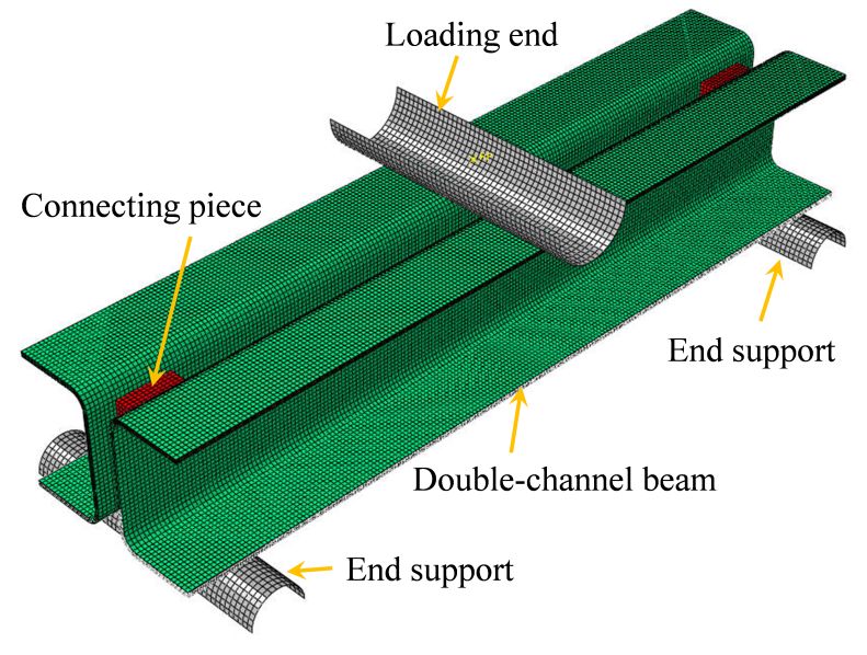
140 | T. Huang et al.

researches have been conducted on the basic mechani-
cal properties of CARALL, such as the in-plane and out-
                                                                  2 Experimental procedures
of-plane bending properties, progressive damage failure
behavior and its affecting factors, and fiber layup optimiza-     2.1 Specimen preparation
tion methods [8–17]. In addition, some studies have focused
on the tensile properties of CARALL and the influence of the      In decomposable truss bridges, the beam members are typ-
orifice stress concentration on the tensile properties [18–22].   ically designed as double-channel cross-sectional profiles
There also exist many research reports on the delamina-           to improve the overall and local stabilities of the channel
tion damage evolution mechanism [23–25], modal analysis           beams. Herein, the double-channel cross-sectional beam
using higher-order theories [26–28], fatigue properties [29–      is composed of two single-channel cross-sectional compo-
32], and impact and post-impact bearing performance of            nents, as illustrated in Figure 1. The entire preparation pro-
CARALL [33–40].                                                   cedure for the CARALL double-channel specimen is as fol-
     Owing to its outstanding characteristics, such as low        lows. First, the CARALL single-channel components were
weight, high strength, high ductility, and high impact            fabricated via the pressure molding thermal curing form-
resistance, CARALL demonstrates broad application po-             ing process. Second, Q235 steel blocks were set between
tential in the development of dismountable bridges. De-           the webs at the ends of the two single-channel members
composable truss bridges consist of beams and columns             as the connecting pieces. The connecting steel blocks and
with a variety of special-shaped cross-sections, such as          the single-channel members’ webs were bonded with Loc-
box, I-shaped, single-channel, and double-channel cross-          tite 9514 super glue. The Y-direction height of the connect-
sections [1]. However, the existing research on FMLs mainly       ing piece was 40 mm, X-direction thickness was 10 mm,
focuses on regular cross-sectional profiles [4–38], and ex-
isting studies on the related research and engineering ap-
plications of special-shaped cross-section members, partic-
ularly the double-channel cross-section, are limited [41, 42].
Therefore, it is necessary to study the load-bearing perfor-
mance and failure mechanism of CARALL with a special-
shaped cross-section, which would promote its application
in large-span decomposable truss bridges.
     In this study, a CARALL beam with a double-channel
cross-section and a 3/2 laminated configuration was consid-
ered as the research object, and its flexural bearing capacity
and failure mechanism were studied by a combination of
experimental and numerical analyses. Two sets of double-
channel cross-sectional laminated beams with carbon fiber
layups of [0∘ /90∘ /0∘ ]3 and [45∘ /0∘ /−45∘ ]3 were prepared     Figure 1: Configuration of CARALL beam with a double-channel
using compression molding and thermosetting forming pro-          cross-section.
cesses. Three-point bending tests of the specimen were
conducted to determine the ultimate bearing capacity and
failure modes. In addition, a user-defined FORTRAN sub-
routine VUMAT suitable for the ABAQUS/Explicit solver
and an analysis algorithm were established to obtain a pro-
gressive damage prediction of the CFRP layer using the
three-dimensional Hashin failure criterion. Furthermore,
the failure mechanism of the two types of CARALL beams
was numerically analyzed in detail.

                                                                  Figure 2: Configuration of CARALL beam with a single-channel cross-
                                                                  section.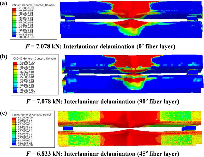
Flexural bearing capacity and failure mechanism of CFRP-aluminum laminate beam |      141

Table 1: Double-channel cross-section member notations, layup sequence, and dimensions (unit: mm).

 Specimen                    Layup configuration                      Al           Thickness         Length      Width       Height
  SHCXL-A               Al/[0/90/0]3 /Al/[0/90/0]3 /Al              2024-T3           1.8             300         30          50
 SHCXL-B             Al/[45/0/−45]3 /Al/[−45/0/45]3 /Al             2024-T3           1.8             300         30          50

Figure 3: Stack and fiber ply configurations of CARALL specimens.

                                                                    Figure 4: Three-point bending test setup for double-channel CARALL
                                                                    beam.
and Z-direction length was 20 mm. For the CARALL single-
channel components, the overall dimensions were 300 mm,
30 mm, and 50 mm in length, width, and height, respec-              in this study, as depicted in Figure 4. The double-channel
tively. The wall thickness was 1.8 mm. The laminated con-           cross-sectional specimen was set as a simplified supporting
figuration was composed of three layers of aluminum al-             condition, and two rolling bars were used as end supports.
loy sheets and two layers of CFRP laminated sheets, as              The center points between the two rolling supports were
depicted in Figure 2. Herein, the longitudinal direction of         260 mm long. A concentrated load F was directly applied on
the channel-shaped beam was defined as the 0∘ direction             the upper surface of the beam members at mid-span. The
of the fiber.                                                       loading process was completed using a WANCE microcom-
     The specific laminate and fiber layup configura-               puter controlled by an electro-hydraulic servo universal
tions of the specimen are depicted in Figure 3. In                  testing machine (1000 kN) from the Shenzhen Wance Test
the experiments, two different fiber layup configura-               Equipment Co., Ltd. Displacement loading was adopted,
tions, referred to as Al/0∘ /90∘ /0∘ /Al/0∘ /90∘ /0∘ /Al and        and the loading rate was set to 1 mm/min. Considering the
Al/45∘ /0∘ /−45∘ /Al/−45∘ /0∘ /45∘ /Al, were employed in the        research purpose, only the ultimate bearing capacity and
fabrication of the single-channel components. In this case,         failure modes of the specimens were determined in the test.
two sets of specimens with different fiber layup configura-
tions were prepared and marked as SHCXL-A and SHCXL-B,
respectively. Three specimens were prepared for each set of
specimens. The SHCXL-A group numbers were SHCXL-A-1,
SHCXL-A-2, and SHCXL-A-3; the SHCXL-B group numbers
                                                                    3 Experimental results
were SHCXL-B-1, SHCXL-B-2, and SHCXL-B-3. The CFRP lay-
                                                                    The failure modes and ultimate bearing capacity of the
ers used in the study were T700/E-302 carbon fiber epoxy
                                                                    SHCXL-A and SHCXL-B beams with double-channel cross-
prepregs (unidirectional board) with a thickness of 0.15 mm
                                                                    sections are summarized in Table 2. The real damage and
provided by Sichuan Xinwanxing Composite Material Co.,
                                                                    failure modes after the specimens lose their bearing capac-
Ltd. The selected aluminum alloy was 2024-T3 with a thick-
                                                                    ity are depicted in Figure 5. Only a few differences were
ness of 0.3 mm.
                                                                    observed in the ultimate bearing capacity and the overall
                                                                    failure mode between the two types of specimens with dif-
                                                                    ferent carbon fiber layers. The ultimate loads acting on the
2.2 Three-point bending test
                                                                    mid-span position of the SHCXL-A and SHCXL-B beams
                                                                    varied from 5.3 to 6.0 kN. The final failure mode under a
As there exists no unified standard for the bending loading
                                                                    three-point bending load was as follows. At the concen-
test of CARALL double-channel cross-sectional members, a
                                                                    trated loading position, the connection location of the up-
self-designed three-point bending test method was adopted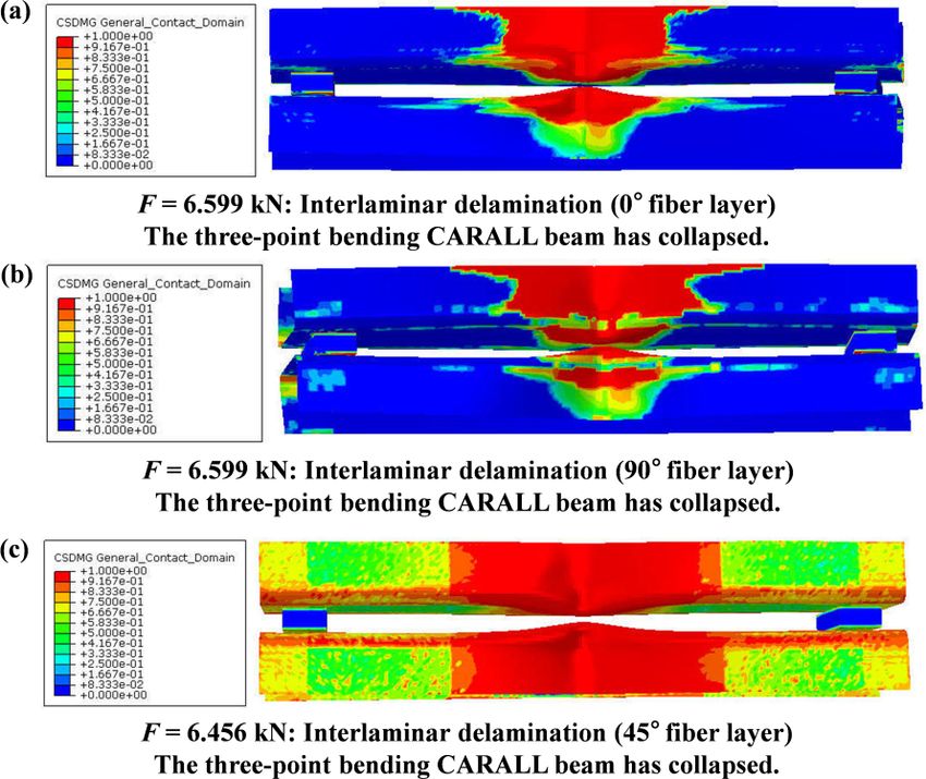
142 | T. Huang et al.
Table 2: Bearing capacity and failure modes of double-channel CARALL beams with different fiber layups.
Specimen Layup Failure modes Ultimate
configuration load (kN)
SHCXL-A-1 0∘ /90∘ /0∘ At the mid-span position, the connection location of the upper flanges 5.496
SHCXL-A-2 0∘ /90∘ /0∘ and webs produced a large buckling deformation. The connecting 5.965
SHCXL-A-3 0∘ /90∘ /0∘ pieces between the members with a single-channel cross-section fell 5.768
off. The upper flange was locally bent and deformed, and interlayer
delamination damage failure between the material layers of the upper
flange occurred.
SHCXL-B-1 45∘ /0∘ /−45∘ At the mid-span position, the connection location of the upper flanges 5.386
SHCXL-B-2 45∘ /0∘ /−45∘ and webs produced a large buckling deformation. The connecting 5.894
SHCXL-B-3 45∘ /0∘ /−45∘ pieces between the members with a single-channel cross-section fell 5.645
off. The upper flange was locally bent and deformed, and interlayer
delamination damage failure between the material layers of the upper
flange occurred.
(a)
(b)
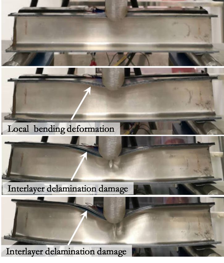
Figure 6: Deformation and failure evolution process of double-
channel CARALL beams.
per flanges and webs first produced large buckling defor-
mations. Subsequently, the two connecting pieces between
the members with a single-channel cross-section fell off.
(c)
Finally, owing to the large local bending deformation of the
Figure 5: Failure modes of double-channel CARALL beams: (a) Local upper flange at the concentrated loading position, signifi-
buckling and deformation of the upper flange and web; (b) connect- cant interlayer delamination damage occurred between the
ing pieces fall off; and (c) interlayer delamination damage of upper material layers of the upper flange, and finally, failure of
flange.
the beam components occurred.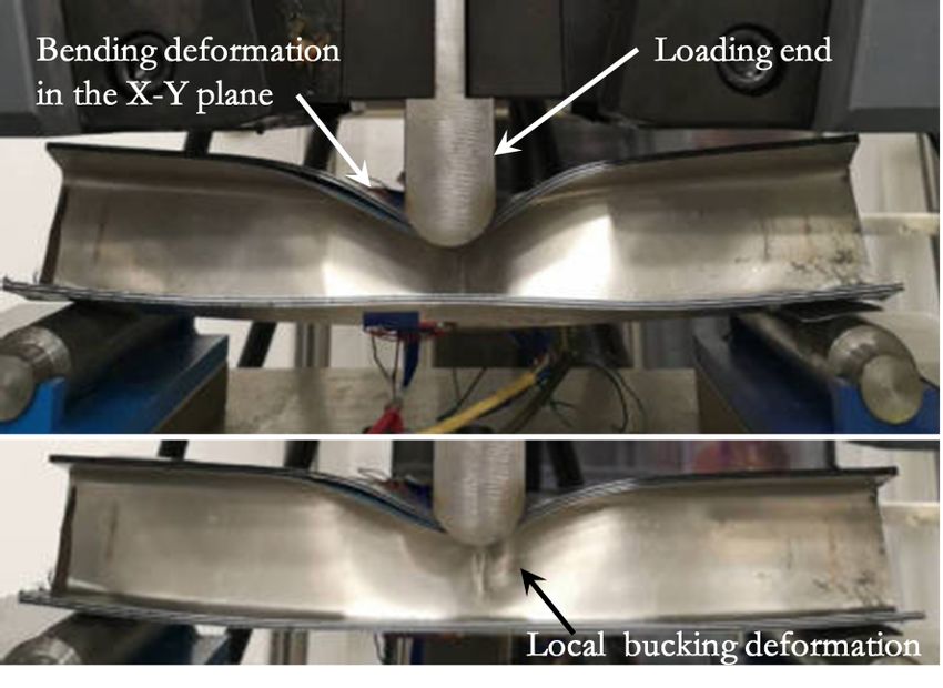
Flexural bearing capacity and failure mechanism of CFRP-aluminum laminate beam |      143

Figure 7: Local bending deformation in X-Y plane of double-channel   Figure 8: Finite element model of double-channel CARALL beams
CARALL beams.                                                        subjected to three-point bending loads.

     Figure 6 illustrates the deformation and failure evolu- 4 Numerical analysis
tion process of the double-channel CARALL beams. From
Figure 5(a) and Figure 6, it can be seen that the ultimate
                                                               4.1 Finite element modeling
bending bearing capacities of the SHCXL-A and SHCXL-B
beams were dependent on the beams’ abilities to resist buck-
                                                               With the aid of the ABAQUS software, the explicit time inte-
ling deformation of the CARALL at the connection between
                                                               gration method (ABAQUS/Explicit) was used to simulate
the upper flanges and webs. The upper flange of the double-
                                                               the bending bearing performance and failure mechanism
channel beams exhibited a high bending resistance in the
                                                               of the aforementioned two types of double-channel CAR-
X-Y plane, and the bending bearing capacity of the beam
                                                               ALL beams. Owing to the limitation of the two-dimensional
components was high. This is because the upper flange at
                                                               Hashin failure criterion in ABAQUS, a VUMAT subroutine
the concentrated loading position can be regarded as a can-
                                                               suitable for the ABAQUS/Explicit solver was developed in
tilever beam, if the location of the connection between the
                                                               FORTRAN to realize the CFRP layer progressive damage
flange and web is considered as the fixed end. The loading
                                                               simulation based on the three-dimensional Hashin failure
end was equivalent to applying a distributed load to the
                                                               criterion.
upper flange. The upper flange then produced a large local
                                                                    Figure 8 depicts the established finite element (FE)
bending deformation in the X-Y plane (see Figure 7), which
                                                               model of the double-channel CARALL beams subjected
caused a large local bending deformation of the connection
                                                               to three-point bending loads. The three-dimensional pro-
between the upper flange and web. With an increase in the
                                                               gressive damage model was used as the material model of
bending deformation, interlayer delamination failure of the
                                                               the CFRP layers, and the eight-node reduced integral solid
laminate finally occurred (see Figures 6 and 7).
                                                               element (C3D8R) was used for the element model of the
     Thus, it can be concluded that, because the upper
                                                               CFRP layers. The elastoplastic constitutive and Johnson-
flange of the double-channel CARALL beam member ex-
                                                               Cook plastic damage criterion [17] were used for the alu-
hibited poor resistance to the bending deformation in the
                                                               minum alloy material, and the aluminum alloy layer was
X-Y plane, the beam members produced a large local bend-
                                                               also discretized by the C3D8R element.
ing deformation at the concentrated loading position. The
                                                                    Note that a key technique in the FE analysis is to sim-
large local bending deformation finally caused the beam to
                                                               ulate delamination growth in composite laminates. Differ-
lose its bearing capacity. The resistance to local bending de-
                                                               ent cohesive models have been used in some existing lit-
formation at the junction of the flange and web determined
                                                               eratures [43–46]. In this paper, the delamination failure
the ultimate load-bearing capacity of the beam, which re-
                                                               prediction between the layers in the laminated beam was
sulted in small differences between the ultimate bearing
                                                               simulated by the cohesive zone model (CZM) method, and
capacity of the two types of beams with different fiber layup
                                                               was  realized by the established three-dimensional cohesive
configurations (0∘ /90∘ /0∘ and 45∘ /0∘ /−45∘ ).
                                                               unit COH3D8. The used CZM method to simulate interfacial
                                                               failure is achieved by defining the surface-based cohesive
                                                               contact. It allows the specification of generalized traction-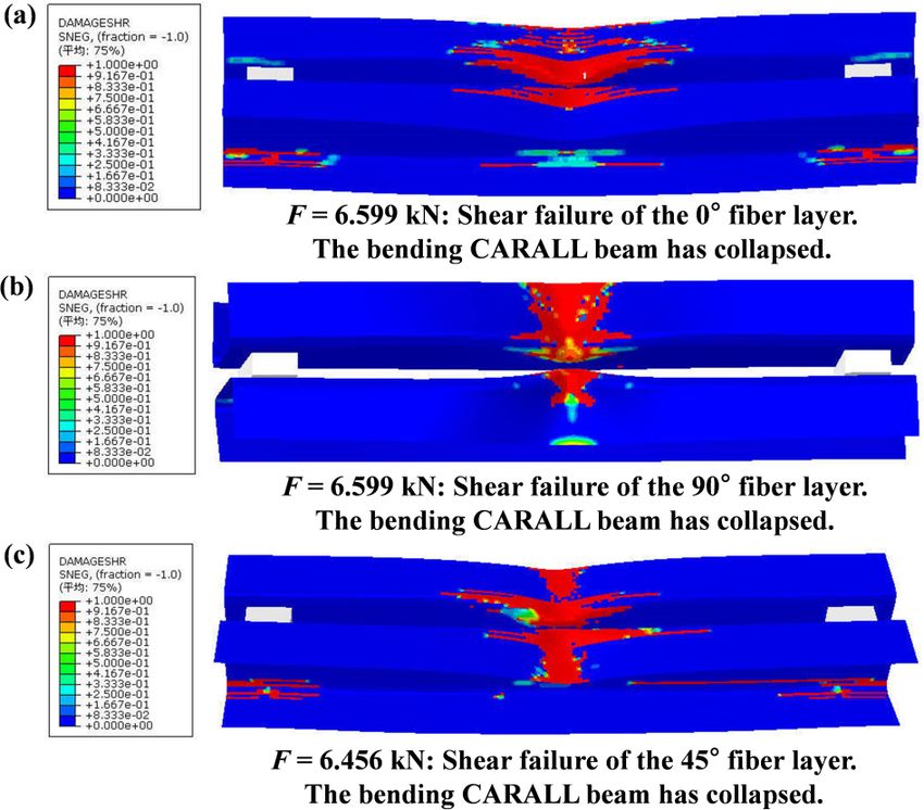
144 | T. Huang et al.

separation behavior of two adjacent surfaces without the             SHCXL-A and SHCXL-B, respectively. By comparing Figure 5
need to employ the cohesive element. The detail cohesive             and Figure 9, it can be observed that, in terms of the final
algorithm selected to handle such interfacial problems can           failure modes of the CARALL beams, the numerical simula-
be found in a previous work [17].                                    tion are consistent with the experimental results, both of
     To finely simulate the influence of the concentrated            which demonstrate that a large local bending deformation
load F and to meet the requirements of the element charac-           and delamination failure occur at the junction of the upper
teristic length while improving the calculation efficiency,          flange and web of the channel beam.
the element grid size was set as 1.5 mm × 1.5 mm. The load-               However, with regard to the ultimate bearing capacity
ing end was coupled to all the nodes through the reference           of the beams, there is a difference between the numerical
point at mid-span, and a displacement of 25 mm along the             simulation and experimental results. The ultimate load
height direction was applied to the reference point.                 obtained by the numerical simulation was greater than
                                                                     the experimental result, as presented in Table 3. The main
                                                                     reason for the relatively large error is that the numerical
4.2 Simulation analysis results                                      simulation results were obtained under ideal conditions.
                                                                     For example, ideal bonding conditions between the layers
Figure 9 depicts the final failure modes of the two types of         of the laminate were assumed in the simulation. However,
double-channel CARALL beams under three-point bending                during the pressure molding thermal curing forming pro-
loads. According to the numerical simulation results, the            cess of the specimens, the operating errors of the personnel
maximum concentrated loads of the two types of beams                 and the machining quality were likely to affect the load-
with different fiber layers were 7.078 kN and 6.824 kN for

Table 3: Comparison of ultimate bearing capacities obtained in numerical simulation and experiment.

    Specimen                Layup configurations                             Ultimate loads (kN)                        Error
                                                                    Simulation                Experiment
    SHCXL-A-1                    0∘ /90∘ /0∘                          7.078                      5.496                 28.7%
    SHCXL-A-2                    0∘ /90∘ /0∘                          7.078                      5.965                 18.7%
    SHCXL-A-3                    0∘ /90∘ /0∘                          7.078                      5.768                 22.7%
    SHCXL-B-1                   45∘ /0∘ /−45∘                         6.823                      5.386                 26.7%
    SHCXL-B-2                   45∘ /0∘ /−45∘                         6.823                      5.894                 15.8%
    SHCXL-B-3                   45∘ /0∘ /−45∘                         6.823                      5.645                 21.0%

 (a)                                                                    (b)

Figure 9: Numerical results of failure modes of double-channel CARALL beams: (a) SHCXL-A and (b) SHCXL-B.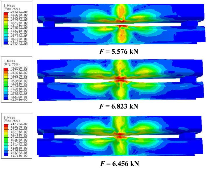
Flexural bearing capacity and failure mechanism of CFRP-aluminum laminate beam |    145

bearing capacity of the fabricated beams. In general, under        beam. The distributed load due to the loading end caused
ideal conditions, the error can be controlled within 30%.          the upper flange to produce a large local bending deforma-
                                                                   tion in the X-Y plane (see Figure 7), thereby resulting in a
                                                                   large local buckling deformation of the outer aluminum
4.3 Failure mechanism analysis                                     alloy sheet at the junction of the upper flange and the web
                                                                   of the beam.
4.3.1 Failure analysis of aluminum alloy sheet                          When the concentrated load at the mid-span reached
                                                                   3.660 kN and 3.066 kN respectively (see Figure 10), the up-
According to the comparative analysis, the outer aluminum          per flange at the concentrated load location of the SHCXL-A
alloy sheet of the beam was the first to produce buckling de-      and SHCXL-B beams exhibited more obvious local buck-
formation, and the damage was the most severe when the             ling deformation, making the stress levels of the outer alu-
beam lost its bearing capacity. Therefore, the failure mech-       minum alloy sheets at the junction of the upper flange and
anism of the double-channel beam under a concentrated              the web 351.4 MPa and 330.8 MPa, respectively. This indi-
load at mid-span was analyzed according to the stress and
deformation process of the outer aluminum alloy sheet, as
depicted in Figure 10. For the SHCXL-A and SHCXL-B beams,
when the mid-span concentrated load only reached 1.035
kN and 1.519 kN respectively, the maximum stress of the
outer aluminum alloy sheet reached 309.6 MPa and 319.4
MPa at the junction of the upper flange and web respec-
tively. When the plastic strain of the 2024-T3 aluminum
alloy was zero, the yield stress was only 300 MPa. This
implies that the outer aluminum alloy sheet had already
undergone local plastic deformation at this time. This is
mainly attributed to the fact that the upper flange at the
concentrated loading position is equivalent to a cantilever

                                                                   (a)

(a)

(b)                                                                (b)

Figure 10: Stress distribution and deformation of outer aluminum   Figure 11: Stress and deformation evolution in outer aluminum
sheet under different concentrated loads: (a) SHCXL-A and (b)      sheet of double-channel CARALL beams: (a) SHCXL-A and (b) SHCXL-
SHCXL-B.                                                           B.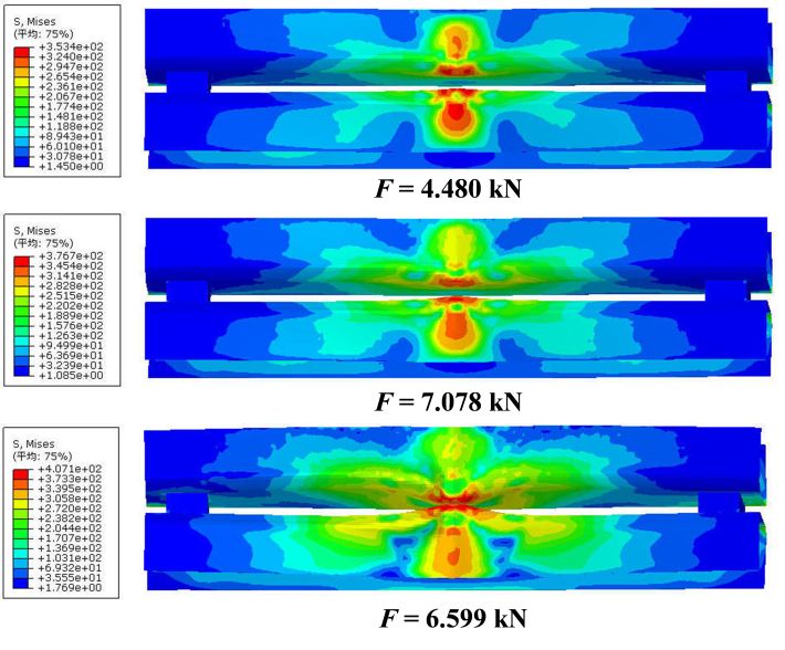
146 | T. Huang et al.

cates that the bending deformation in the X-Y plane of the
upper flange increased, resulting in a larger plastic defor-
mation of the outer aluminum alloy sheet at the junction of
the flange and web. However, at this time, the distribution
range of the high-stress area was still relatively small, and
the beam webs did not exhibit any evident local bending de-
formation. The above phenomenon also indicates that the
upper flange of the beam with a fiber layer of 45∘ /0∘ /−45∘
had a strong ability to resist bending deformation (con-
centrated load: 1.519 kN > 1.035 kN ). Once the aluminum
alloy sheet deformed plastically, its ability to resist bending
deformation in the X-Y plane reduced (concentrated load:
3.066 kN < 3.660 kN).
     When the concentrated loads acting on the SHCXL-A
and SHCXL-B beams reached 4.480 kN and 5.576 kN re-
                                                                  Figure 12: Initial interlaminar delamination failure area distribution
spectively (see Figure 11), the local buckling deformation of
                                                                  of double-channel CARALL beams: (a) SHCXL-A: 0∘ fiber layer; (b)
the outer aluminum alloy sheet at the connection between          SHCXL-A: 90∘ fiber layer; and (c) SHCXL-B: 45∘ fiber layer.
the upper flanges and webs was relatively obvious. More-
over, the high-stress distribution area also increased. When
the concentrated loads acting at the mid-span reached the         of the interlaminar delamination failure for each layer of
ultimate bearing capacities of 7.078 kN and 6.823 kN, the         the laminated panels was analyzed on the basis of the in-
stresses acting on the outer aluminum alloy sheet were            terlaminar delamination between the fiber layer of ply0-1-1
376.7 MPa and 404 MPa, respectively, and more obvious             or the fiber layer of ply45-1-1 and its adjacent layers, and
local buckling deformation occurred at the junction of the        between the ply90-1-1 fiber layer and its adjacent layers.
upper flange and web. At this time, the concentrated load         The first 0∘ CFRP fiber layer in the 3/2 laminated panels
acting on the SHCXL-A beam was larger than that acting            of SHCXL-A was designated as ply0-1-1. The first 45∘ CFRP
on the SHCXL-B beam (7.078 kN > 6.823 kN). However, the           fiber layer of SHCXL-B was designated as ply45-1-1. The first
stress acting on the outer aluminum alloy sheet decreased         90∘ fiber layer was designated as ply90-1-1, as depicted in
(376.7 MPa < 404 MPa), which further indicated that once          Figure 3.
the aluminum alloy sheet deformed plastically, the upper               As illustrated in Figures 12a and 12b, when the concen-
flange of the CARALL beam with the fiber layup configu-           trated load on the SHCXL-A beam reached approximately
ration of 0∘ /90∘ /0∘ had a strong ability to resist bending      2.484 kN and 1.7 kN, the stratification evolution factors be-
deformation in the X-Y plane.                                     gan to appear between the fiber layer of ply0-1-1 and its
     In conclusion, the above results further verify that the     adjacent layers and between the fiber layer of ply90-1-1 and
key factors leading to the loss of the ultimate bearing ca-       its adjacent layers, respectively. When the concentrated
pacity of the beam members are that the upper flange of the       load on the SHCXL-B beam reached approximately 1.519 kN,
double-channel CARALL beam is equivalent to a cantilever          interlaminar delamination began to appear between the
beam with elastic restraint fixed ends under a distributed        ply45-1-1 fiber layer and its adjacent layers (see Figure 12c).
load, and that the junction of the upper flange and web           Moreover, the extension area of the interlayer delamination
continuously provides the bending load in the X-Y plane to        failure was large. This indicates that, in the initial state of
the web, resulting in a larger local buckling deformation.        the concentrated load bearing of the beam, the resistance
                                                                  of the 0∘ fiber layer to delamination was stronger than that
                                                                  of the 90∘ and 45∘ fiber layers. This implies that the fiber
4.3.2 Failure analysis of interlaminar delamination               orientation angle weakens the ability of the fiber layer to
                                                                  resist interlaminar delamination damage.
According to the comparative analysis, there were large                For the SHCXL-A and SHCXL-B beams, when the con-
interlaminar delamination failure areas between the fiber         centrated loads reached the ultimate bearing capacities
layer of ply0-1-1 (or the fiber layer of ply45-1-1) and its ad-   of the two types of beams, the delamination failure area
jacent layers, and between the ply90-1-1 fibre layer and its      evidently increased in comparison with that of the previ-
adjacent layers. The degree of damage was the most severe         ously mentioned results (see Figure 13). The failure area of
when the CARALL beam collapsed. Therefore, the evolution          the interlaminar delamination between the ply45-1-1 fiber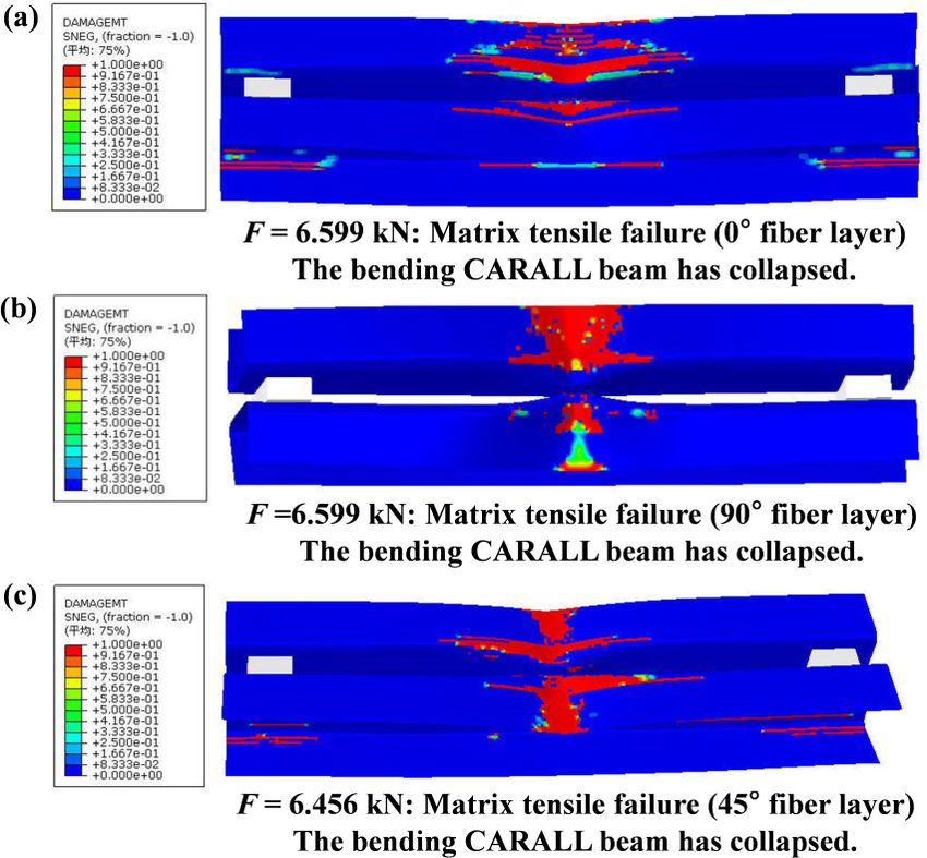
Flexural bearing capacity and failure mechanism of CFRP-aluminum laminate beam |             147

Figure 13: Delamination failure area distribution of double-channel
CARALL beams in ultimate bearing state: (a) SHCXL-A: 0∘ fiber layer;
                                                                       Figure 14: Delamination failure area distribution of double-channel
(b) SHCXL-A: 90∘ fiber layer; and (c) SHCXL-B: 45∘ fiber layer.
                                                                       CARALL beams at final failure state: (a) SHCXL-A: 0∘ fiber layer; (b)
                                                                       SHCXL-A: 90∘ fiber layer; and (c) SHCXL-B: 45∘ fiber layer.

layer and the adjacent layers of the SHCXL-B beam was
the largest (see Figure 13c), and the delamination failure             deformation. Therefore, the interlayer delamination failure
area between the ply90-1-1 fiber layer and its adjacent lay-           was the main factor for the loss of the bearing capacity
ers was the smallest (see Figure 13b). Delamination failure            of the CARALL beams. In addition, regardless of the load
between the 0∘ or 90∘ fiber layer and its adjacent layers              level, the delamination failure distribution area between
mainly occurred at the flange and at the junction of the               the ply0-1-1 (or ply90-1-1) fiber layer and its adjacent layers
web and flange of the double-channel beams. Interlaminar               for the SHCXL-A beam was smaller than that of the ply45-1-1
delamination failure occurred between the 45∘ fiber layer              fiber layer and its adjacent layers for the SHCXL-B beam,
and the adjacent layers on the web and flange within a large           which suggests that, in comparison with the 0∘ or 90∘ fiber
area (see Figure 13c).                                                 layup, the 45∘ fiber layup had a weaker ability to resist
     With regard to the SHCXL-A and SHCXL-B beams (see                 delamination damage between layers.
Figure 14), the failure degree and failure area of the de-
lamination between the ply0-1-1 or ply90-1-1 and ply45-1-1
fiber layers and their adjacent layers on the flange were              4.3.3 Failure analysis of fiber tension and compression
greater than those in the previously mentioned results (see
Figures 12 and 13). In comparison with the delamination                Figures 15 and 16 depicts the damage evolution process of
failure between the 90∘ (or 0∘ ) fiber layer and the adjacent          the fiber tensile and compression failures for the ply0-1-1,
fiber layer of the SHCXL-A beam, the failure area and fail-            ply90-1-1, and ply45-1-1 fiber layers in the CFRP prepregs of
ure degree between the 45∘ fiber layer and the adjacent                the two types of beams with different fiber layups. When
fiber layer of the SHCXL-B beam were larger. Moreover, the             the two types of beams lost their bearing capacity and col-
connection between the flanges and webs was completely                 lapsed, the fiber tensile damage was almost zero, and the
stratified along the length of the double-channel beam.                fiber compression damage was only slightly more severe
     With a gradual increase in the concentrated load, the             than the tensile damage. A layer-by-layer analysis reveals
delamination failure area between the ply0-1-1, ply90-1-1,             that the fiber tensile and compression damage levels of
and ply45-1-1 fiber layers, and their adjacent layers gradually        all other fiber layers were smaller than those of ply0-1-1 or
expanded. The delamination failure area was still local                ply90-1-1 and ply45-1-1 fiber layers. It can be concluded that,
until the beam lost its bearing capacity. In the longitudinal          when the main damage mode and the corresponding de-
direction, a larger range of delamination failure occurred             formation of the double-channel CARALL beams were the
only near the concentrated loading position at the mid-span            local bending and buckling deformation of the flange and
of the CARALL beams. These local interlayer delamination               web, the fiber tensile and compression damage had almost
failures caused separation between the laminated layers                no effect on the overall failure of the beams.
and reduced the ability of the upper flange to resist bending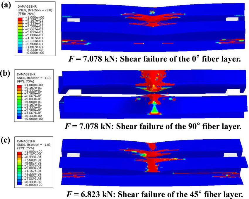
148 | T. Huang et al.

4.3.4 Failure analysis of matrix tension and compression               of ply0-1-1, ply90-1-1, and ply45-1-1 fiber layers had already
                                                                       suffered tensile and compression damage. Therefore, as-
Figures 17 to 22 illustrate the evolution of the tensile and           suming that the main failure modes of the double-channel
compression damage on the fiber layer matrix of ply0-1-1,              CARALL beam members were the local buckling deforma-
ply90-1-1, and ply45-1-1 in CFRP prepregs of the two differ-           tion of the flange and web under concentrated loads, the
ent types of double-channel CARALL beams subjected to                  ability to resist matrix tension and compression damage
three-point bending loads. When the mid-span acting con-               for the fiber layers decreased in the order 90∘ fiber layer
centrated loads of the two types of double-channel CARALL              > 45∘ fiber layer > 0∘ fiber layer at the initial stage of load
beams reached 0.486 kN, 3.659 kN, and 1.519 kN, the matrix             bearing.
                                                                            When the load acting at the mid-span of the laminated
                                                                       beam reached the ultimate bearing capacity and the lam-
                                                                       inated beam lost its bearing capacity, the matrix tensile

Figure 15: Failure evolution process of fiber tension in CFRP layers
of double-channel CARALL beam: (a) SHCXL-A: 0∘ fiber layer; (b)
SHCXL-A: 90∘ fiber layer; and (c) SHCXL-B: 45∘ fiber layer.            Figure 17: Initial matrix tensile failure area distribution of fiber
                                                                       layers of double-channel CARALL beam: (a) SHCXL-A: 0∘ fiber layer;
                                                                       (b) SHCXL-A: 90∘ fiber layer; and (c) SHCXL-B: 45∘ fiber layer.

Figure 16: Failure evolution process of fiber compression in CFRP      Figure 18: Matrix tensile failure area distribution of fiber layers in
layers of double-channel CARALL beam: (a) SHCXL-A: 0∘ fiber layer;     ultimate bearing state: (a) SHCXL-A: 0∘ fiber layer; (b) SHCXL-A: 90∘
(b) SHCXL-A: 90∘ fiber layer; and (c) SHCXL-B: 45∘ fiber layer.        fiber layer; and (c) SHCXL-B: 45∘ fiber layer.
Flexural bearing capacity and failure mechanism of CFRP-aluminum laminate beam | 149
Figure 21: Matrix compression failure area distribution of fiber
layers in ultimate bearing state: (a) SHCXL-A: 0∘ fiber layer; (b)
Figure 19: Matrix tensile failure area distribution of fiber layers in SHCXL-A: 90∘ fiber layer; and (c) SHCXL-B: 45∘ fiber layer.
final failure state: (a) SHCXL-A: 0∘ fiber layer; (b) SHCXL-A: 90∘ fiber
layer; and (c) SHCXL-B: 45∘ fiber layer.
Figure 22: Matrix compression failure area distribution of fiber
Figure 20: Initial matrix compression failure area distribution of layers in final failure state. (a) SHCXL-A: 0∘ fiber layer; (b) SHCXL-A:
fiber layers: (a) SHCXL-A: 0∘ fiber layer; (b) SHCXL-A: 90∘ fiber layer; 90∘ fiber layer; and (c) SHCXL-B: 45∘ fiber layer.
and (c) SHCXL-B: 45∘ fiber layer.
of 90∘ , 45∘ , and 0∘ . Thus, it can be concluded that their
failure areas of the ply0-1-1 fiber layer were distributed in ability to resist matrix compression damage decreased in
stripes, while the matrix tensile failure areas of the ply90-1- the order 90∘ fiber layer > 45∘ fiber layer > 0∘ fiber layer.
1 and ply45-1-1 fiber layers were distributed in blocks (see
Figures 18 and 19). This implies that under the existing load-
ing conditions, the ply0-1-1 fiber layer exhibits the strongest 4.3.5 Shear failure analysis of fiber layer
ability to resist matrix tensile damage.
As can be seen from Figures 21 and 22, the matrix com- Figures 23 to 25 depict the shear failure evolution process of
pression failure distribution areas of the ply0-1-1, ply90-1-1, ply0-1-1, ply90-1-1, and ply45-1-1 fiber layers in CFRP prepregs
and ply45-1-1 fiber layers assumed a block-like distribution, of the two different types of beams under three-point bend-
and size of the distribution areas was arranged in the order ing loads. When the double-channel CARALL beams with150 | T. Huang et al.
Figure 23: Initial shear failure area distribution of fiber layers: (a) Figure 24: Shear failure area distribution of fiber layers in ultimate
SHCXL-A: 0∘ fiber layer; (b) SHCXL-A: 90∘ fiber layer; and (c) SHCXL- bearing state: (a) SHCXL-A: 0∘ fiber layer; (b) SHCXL-A: 90∘ fiber
B: 45∘ fiber layer. layer; and (c) SHCXL-B: 45∘ fiber layer.
the 0∘ /90∘ /0∘ fiber layups were subjected to a concen-
trated load of 0.486 kN at the mid-span (see Figure 23a), the
shear damage failure of the ply0-1-1 fiber layer had already
occurred. However, the concentrated load of the double-
channel beams with 45∘ / 0∘ /−45∘ fiber layups must reach
1.519 kN for shear damage failure of the ply45-1-1 fiber layer
to occur (see Figure 23c). For the double-channel CARALL
beam members with the 0∘ /90∘ /0∘ fiber layups, the shear
failure of the ply90-1-1 fiber layer occurred only when the
concentrated load reached 3.659 kN (see Figure 23b). This
indicates that, at the initial stage of load bearing, the ability
of the ply90-1-1 fiber layer to resist the shear damage failure
of the double-channel beams was stronger than that of the
ply0-1-1 and ply45-1-1 fiber layers.
In addition, after the double-channel CARALL beam
reached its ultimate bearing capacity and lost its load-
bearing ability, the shear failure distribution areas of the Figure 25: Shear failure area distribution of fiber layers in final
failure state: (a) SHCXL-A: 0∘ fiber layer; (b) SHCXL-A: 90∘ fiber
fiber layer of ply0-1-1 and ply45-1-1 were in strips and blocks.
layer; and (c) SHCXL-B: 45∘ fiber layer.
However, the shear failure distribution areas of the fiber
layer of ply90-1-1 were in blocks (see Figures 24 and 25). The
shear damage failure distribution area of the ply0-1-1 fiber
layer was smaller than those of the ply45-1-1 and ply90-1-1
5 Conclusions
fiber layers, which further indicated that, in comparison
In this study, two sets of double-channel CARALL beams us-
with the ply90-1-1 and ply45-1-1 fiber layers, the ply0-1-1 fiber
ing different fiber layup configurations ([0∘ /90∘ /0∘ ]3 and
layer exhibited stronger resistance to shear failure. As the
[45∘ /0∘ /−45∘ ]3 ) were prepared via the pressure molding
load continued to increase, the shear failure range of the
thermal curing forming process and subjected to three-
ply0-1-1, ply90-1-1, and ply45-1-1 fiber layers gradually ex-
point bending loads. The flexural bearing capacity and
panded, which undoubtedly intensified the local bending
failure mechanism of the CARALL beams were experimen-
deformation at the junction of the flange and web of the
tally and numerically studied. The major findings of this
double-channel CARALL beams, causing the beams to lose
study can be summarized as follows:
their overall bearing capacity.Flexural bearing capacity and failure mechanism of CFRP-aluminum laminate beam | 151
(1) Owing to the weak bending resistance of the lami- and Young Elite Scientist Sponsorship. All extended sup-
nated beam flange in the X-Y plane, the final failure port is gratefully acknowledged.
mode of the two types of CARALL beams under the
concentrated load at mid-span was the local large
bending deformation at the junction of the flange
and web. This failure mode indicated that different
References
fiber layup configurations had no evident influence [1] Brittani RR, Ashley PT. Portable and rapidly deployable bridges:
on the bending bearing performance of the double- Historical perspective and recent technology developments. Jour-
channel CARALL beam. The ultimate bending bear- nal of Bridge Engineering 2013; 18: 1074–1085.
ing capacity of both types of beams was not high, and [2] Zhang DD, Zhao QL, Huang YX, et al. Flexural properties of a
the materials were not fully utilized. lightweight hybrid FRP-aluminum modular space truss bridge
system. Composite Structures 2014; 108(1): 600–615.
(2) The ultimate loss of load-bearing capacity of the two
[3] Zhang DD, Lv YR, Zhao QL, et al. Development of lightweight emer-
types of CARALL beams was caused by the large lo- gency bridge using GFRP–metal composite plate-truss girder.
cal bending and buckling damage generated at the Engineering Structures 2019; 196:109291.
junction of the upper flange and web rather than by [4] Zhang DD, Yuan JX, Zhao QL, et al. Static performance of a new
the damage of the aluminum sheet or the fiber ten- GFRP-metal string truss bridge subjected to unsymmetrical loads.
Steel and Composite Structures 2020; 35(5): 641–657.
sile or compression failure of the CFRP prepregs. The
[5] Sinmazçelik T, Avcu E, Bora MO, et al. A review: fibre metal lam-
large local bending and buckling damage was mainly inates,background, bonding types and applied test methods.
caused by the interlaminar delamination damage Materials & Design 2011; 32: 3671–3685.
between each unidirectional laminated plate at the [6] Ding ZR, Wang HY, Luo JM, et al. A review on forming technologies
concentrated loading position, matrix tensile or com- of fibre metal laminates. International Journal of Lightweight
pression damage, and shear failure of the fiber layers. Materials and Manufacture 2020; 4(1): 110–126.
[7] Kavitha K, Vijayan R, Sathishkumar T. Fibre-metal laminates: A re-
(3) At the initial stage of damage, the resistance of the
view of reinforcement and formability characteristics. Materials
fiber layers of the laminated beams to fiber tensile Today: Proceedings 2020; 22: 601–605.
and compression damage, matrix tension and com- [8] Caprino G, Iaccarino P, Lamboglia A. The effect of shear on the
pression damage, and shear damage of fiber layers rigidity in the three point bending of unidirectional CFRP lami-
decreased in the order 90∘ fiber layer > 45∘ fiber layer nates made of T800H/3900-2. Composite Structures 2009; 88:
360–376.
> 0∘ fiber layer. The resistance of the fiber layers to
[9] Dong CS, Jayawardena H, Davies IJ. Flexural properties of hybrid
interlaminar delamination damage decreased in the composites reinforced by S-2 glass and T700S carbon fibres.
order 0∘ fiber layer > 90∘ fiber layer > 45∘ fiber layer. Composites Part B: Engineering 2012; 43: 573–581.
Therefore, it is suggested that the load-bearing perfor- [10] Alhashmy HA and Nganbe M. Laminate squeeze casting of carbon
mance could be improved if the three laminated fiber fiber reinforced aluminum matrix composites. Materials & Design
layers, i.e., the 90∘ , 0∘ , and 45∘ fibers, are mixed. 2015; 67: 154–158.
[11] Xue J, Wang WX, Zhang JZ, et al. Progressive failure analysis of
(4) The VUMAT subroutine based on FORTRAN for the
the fiber metal laminates based on chopped carbon fiber strands.
ABAQUS/Explicit display analysis algorithm can be Journal of Reinforced Plastics and Composites 2015; 34(5): 364–
used to reveal the progressive damage of the CFRP 376.
layer with the three-dimensional Hashin progressive [12] Dhaliwal GS, Newaz GM. Experimental and numerical investi-
damage criterion. When factors, such as specimen gation of flexural behavior of carbon fiber reinforced aluminum
laminates. Journal of Reinforced Plastics and Composites 2016;
preparation and test errors, were considered, the ul-
35(12): 945–956.
timate bearing capacity and failure modes obtained [13] Zakaria AZ, Shelesh-nezhad K, Chakherlou TN, et al. Effects of
from the experiments were in good agreement with aluminum surface treatments on the interfacial fracture tough-
the numerical solutions. In general, the established ness of carbon-fiber aluminum laminates. Engineering Fracture
FE model can be used to predict the failure behavior Mechanics 2017; 172: 139–151.
of this type of CARALL beam. In future studies, ad- [14] Khan F, Qayyum F, Asghar W, et al. Effect of various surface prepa-
ration techniques on the delamination properties of vacuum in-
vances numerical analysis with higher-order theories
fused Carbon fiber reinforced aluminum laminates (CARALL): Ex-
will be performed for the CARALL beams. perimentation and numerical simulation. Journal of Mechanical
Science and Technology 2017; 31(11):5265–5272.
Acknowledgement: This research was supported by the Na- [15] Osapiuk M, Bienias J, Surowska B. Analysis of the bending
tional Natural Science Foundation of China (51708552), Nat- and failure of fiber metal laminates based on glass and carbon
fibers. Science and Engineering of Composite Materials 2018;
ural Science Foundation of Jiangsu Province (BK20170752),
25(6):1095–1106.152 | T. Huang et al.
[16] Xu RH, Huang YX, Lin Y, et al. In plane flexural behaviour and [31] Montesano J, Fawaz Z, Bougherara H. Use of infrared thermog-
failure prediction of carbon fibre reinforced aluminium laminates. raphy to investigate the fatigue behavior of a carbon fiber re-
Journal of reinforced plastics and composites 2017; 36(18): 1384– inforced polymer composite. Composite Structures 2013; 97:
1399. 76–83.
[17] Lin Y, Huang YX, Huang T, et al. Characterization of progressive [32] Stoll MM, Weidenmann KA. Fatigue of fiber-metal-laminates
damage behaviour and failure mechanisms of carbon fiber re- with aluminum core, CFRP face sheets and elastomer interlayers
inforced aluminium laminates under three-point bending. Thin- (FMEL). International Journal of Fatigue 2018; 107: 110–118.
walled Structures 2019; 135:494–506. [33] Bienias J, Jakubczak P. Low velocity impact resistance of
[18] Mao CW, Mo F, Peng YN, et al. Carbon fiber composite laminate aluminium/carbon-epoxy fiber metal laminates. Composite The-
structure and effect of clearance on riveting properties. Acta Ma- ory and Practice 2012; 12: 193–197.
teriae Compositae Sinica 2018; 35(12): 3280–3297 (in Chinese). [34] Wang B, Xiong J, Wang XJ, et al. Energy absorption eflciency of
[19] Zhang YH, Yan LL, Miao MH, et al. Microstructure and mechanical carbon fiber reinforced polymer laminates under high velocity
properties of z-pinned carbon fiber reinforced aluminum alloy impact. Materials & Design 2013; 50: 140–148.
composites. Materials & Design 2015; 86: 872–877. [35] Moriniere FD, Alderliesten RC, Sadighi M, et al. An intergrated
[20] Kim JG, Kim HC, Kwon JB, et al. Tensile behavior of alu- study on the low-velocity impact response of the GLARE fiber-
minum/carbon fiber reinforced polymer hybrid composites at metal laminate. Composite Structures 2013; 100: 89–103.
intermediate strain rates. Journal of Composite Materials 2015; [36] Bienias J, Jakubczak P, Surowska B, et al. Low-energy impact be-
49: 1179–1193. haviour and damage characterization of carbon fibre reinforced
[21] André NM, Goushegir SM, Santos JF, et al. Friction spot join- polymer and aluminium hybrid laminates. Archives of Civil and
ing of aluminum alloy 2024-T3 and carbon-fiber-reinforced poly Mechanical Engineering 2015; 15: 925–932.
(phenylene sulfide) laminate with additional PPS film interlayer: [37] Yu GC, Wu LZ, Ma L, et al. Low velocity impact of carbon fiber
Microstructure, mechanical strength and failure mechanisms. aluminum laminates. Composite Structures 2015; 119: 757–766.
Composites Part B: Engineering 2016; 94(1): 197–208. [38] Jaroslaw B, Barbara S, Patryk J. The comparison of low-velocity
[22] Lin Y, Huang YX, Huang T, et al. Open-hole tensile behavior and impact resistance of aluminum/carbon and glass fiber metal
failure prediction of carbon fibre reinforced aluminium laminates. laminates. Polymer Composites 2016; 37: 1056–1063.
Polymer composites 2018; 39: 4123–4138. [39] Kaboglu C, Mohagheghian I, Zhou J, et al. High-velocity impact
[23] Botelho EC, Silva RA, Pardini LC, et al. Evaluation of adhesion of deformation and perforation of fibre metal laminates. Journal of
continuous fiber-epoxy composite/aluminum laminates. Journal Materials Science 2017; 534: 4209–4228.
of Adhesion Science and Technology 2004; 18: 1799–1813. [40] Dhaliwal GS, Newaz GM. Compression after impact characteris-
[24] Makeev A. Interlaminar shear fatigue behavior of glass/epoxy tics of carbon fiber reinforced aluminum laminates. Composite
and carbon/epoxy composites [J]. Composites Science and Tech- Structures 2017; 160: 1212–1224.
nology 2013; 80: 93–100. [41] Shen Y, Ke J, Wu ZZ. Energy-absorbing characteristics of carbon
[25] Li X, Gao W, Liu W. Post-buckling progressive damage of CFRP fiber reinforced polymer composite-AL square tubes with dif-
laminates with a large-sized elliptical cutout subjected to shear ferent braiding angles. Acta Materiae Compositae Sinica 2020;
loading. Composite Structures 2015; 128: 313e321. 37(3): 591–600 (in Chinese).
[26] Kumar S K, Harursampath D, Carrera E, et al. Modal analysis of [42] Shin DK, Kim HC, Lee JJ. Numerical analysis of the damage behav-
delaminated plates and shells using Carrera Unified Formulation ior of an aluminum/CFRP hybrid beam under three point bending.
- MITC9 shell element. Mechanics of Advanced Materials and Composites Part B: Engineering 2014; 56: 397–407.
Structures 2018; 25(8): 681–697. [43] Dimitri R, Trullo M, Zavarise G, et al. A consistency assessment
[27] Pagani A, Valvano S, Carrera E. Analysis of laminated compos- of coupled cohesive zone models for mixed-mode debonding
ites and sandwich structures by variable-kinematic MITC9 plate problems. Frattura Ed Integrità Strutturale 2014; 8(29):266–283.
elements. Journal of Sandwich Structures and Materials 2018; [44] Dimitri R , Trullo M , Lorenzis LD , et al. Coupled cohesive zone
20(1): 4–41. models for mixed-mode fracture: A comparative study. Engineer-
[28] Alaimo A, Orlando C, Valvano S. An alternative approach for ing Fracture Mechanics 2015; 148(1):145–179.
modal analysis of stiffened thin-walled structures with advanced [45] Ridha M, Wang C H, Chen B Y, et al. Modelling complex progres-
plate elements. European Journal of Mechanics - A/Solids 2019; sive failure in notched composite laminates with varying sizes
77: 103820. and stacking sequences. Composites Part A: Applied Science
[29] Cortes P, Cantell WJ. The tensile and fatigue properties of carbon and Manufacturing 2014; 58: 16–23.
fiber-reinforced PEEK-titanium fiber-metal laminates. Journal of [46] Shin D K, Kim H C, Lee J J. Numerical analysis of the damage
Reinforced Plastics and Composites 2004; 23:1615–1623. behavior of an aluminum/CFRP hybrid beam under three point
[30] Liu PF, Chu JK, Liu YL, et al. A study on the failure mechanisms bending. Composites Part B: Engineering 2014; 56:397–407.
of carbon fiber/epoxy composite laminates using acoustic emis-
sion. Materials & Design 2012; 37: 228–235.You can also read