SPIN COMMISSIONING AND DROP TESTS OF A 130 kW-hr COMPOSITE FLYWHEEL
←
→
Page content transcription
If your browser does not render page correctly, please read the page content below
This paper was presented at:

          SPIN COMMISSIONING AND DROP TESTS OF A 130 kW-hr
                       COMPOSITE FLYWHEEL
                          Matthew T. Caprio, Brian T. Murphy, John D. Herbst
                          The University of Texas at Austin, Center for Electromechanics
                                 1 University Station R7000, Austin, TX 78712
                                            mcaprio@mail.utexas.edu

ABSTRACT                                                    double-acting PM bias thrust bearing [4]. To support
     The Center for Electromechanics at the University      the rotor while at rest or in the event of a magnetic
of Texas at Austin is developing a power averaging          bearing system fault, a set of rolling element backup
flywheel battery for use on high speed passenger trains     bearings is mounted at each shaft end. The backup
as part of the Federal Railroad Administration’s Next       bearings are mounted in oil squeeze film dampers to
Generation High Speed Rail Program. The flywheel            reduce impact loading on the bearings during a
rotor, which weighs 5100 lb, is designed to store 130       delevitation, and increase bearing life. A cutaway
kW-hr of energy at a peak design speed of 15,000 rpm.       section of the ALPS flywheel with the full 15 ring rotor
The graphite-epoxy composite rotor, which runs in a         can be seen in Figure 1, showing the main components
vacuum, is supported by a 5 axis active magnetic            of the magnetic bearing and backup bearing systems.
bearing system. A high speed 2 MW motor-generator,          The internal composite burst liner and external motor
which is outside the vacuum, is directly coupled to the     generator are not shown.
flywheel with an industrial disk pack coupling, through
a custom integral rotary vacuum seal.
     This paper begins with a brief description of the
design of the vertically oriented flywheel rotor/housing
system. The partially complete rotor (currently 3000 lb
mass) has recently been undergoing system level
laboratory commissioning. Test results are presented
demonstrating the performance of the magnetic
bearings. Since flywheel system safety is such a critical
issue at this energy level, satisfactory performance of
the backup bearings was demonstrated experimentally.
Delevitation “drop” tests have been performed onto
rolling element backup bearings, and behavior is
reported and compared to related flywheels discussed in
the literature. Finally, testing of a semi-passive whirl
arresting scheme is presented.

FLYWHEEL SYSTEM DESCRIPTION
     The ALPS flywheel is the energy storage
component of a hybrid-electric locomotive power
system for use in a high speed passenger rail                  Figure 1. ALPS flywheel rotor and magnetic bearing system
application [1]. The design speed range of the flywheel
is 7500-15000 rpm, providing 100 kW-hr of delivered         LABORATORY TESTING
energy at up to 2 MW power rating [2]. To withstand              In the interest of safety, the test plan of the ALPS
the spin stresses of the supersonic tip speed, the main     flywheel calls for two phases of commissioning and
rotor body is constructed of filament wound graphite-       laboratory spin testing before eventual integration of
epoxy composite [3].                                        the flywheel into the locomotive for “rolling
     The vertically oriented rotor is supported by a 5      demonstrations” in the dynamic environment.
axis active magnetic bearing system employing               “Intermediate spin testing”, the first laboratory testing
permanent magnet bias homopolar radial bearings and a       phase, is designed to exercise all flywheel systems and
components at full speed, though at reduced energy          component. Since the magnetic materials employed in
levels, through the use of the partially constructed 3000   these high speed bearing laminations are not well
lb rotor. This paper discusses only this current phase of   characterized, there is a significant amount of
testing.                                                    uncertainty in the bearing hysteresis and eddy current
     The partial rotor for intermediate spin testing        loss predictions. Thus, experimental data from the
consists of only the first 6 of the final 15 composite      endurance runs will be incorporated into the thermal
rings installed on the rotor shaft assembly, providing a    model of the rotor to refine the predictions of the
maximum energy of approximately 25 kW-hr at full            magnetic bearing losses.
design speed. The burst liner is not installed into the
flywheel housing for this phase of testing as the full
energy of the rotor in this configuration can be safely
contained by the stainless steel vessel in the unlikely
event of a ring burst. These tests are performed in the
CEM concrete spin test facility, with the housing
mounted rigidly to the mount structure by way of
pedestal struts. Figure 2 shows the ALPS flywheel in
the CEM spin test bunker during intermediate spin
testing. In place of the motor generator, a 400 HP
hydraulic motoring system and speed increasing
gearbox provide the drive for this phase of low power,
low energy, full speed testing.
     The goals of intermediate spin testing are to: 1)
demonstrate the rotordynamic performance of the
flywheel, 2) commission and tune the magnetic bearing
system, 3) test the effectiveness of the backup bearing
system, 4) collect experimental data on the thermal
management of rotor losses to determine maximum
allowable run time, and 5) evaluate the performance of
auxiliary systems.
     To date, the flywheel has been successfully
commissioned to a speed of 13,600 rpm. Only minor
tuning of the magnetic bearing compensator has been
necessary as the measured transfer functions have                  Figure 2. ALPS flywheel in laboratory spin testing
closely matched the predicted modes.            Auxiliary
systems, including the vacuum system, shaft seal, seal      DROP TESTING
compliant bellows mount, and the radial bearing stator           The backup bearing system of the ALPS flywheel
water-cooling system have functioned well.                  is essential for the safe shutdown of the flywheel in the
     While the stability and controllability of the rotor   event of a magnetic bearing system failure. The system
has been satisfactory, a mode of the coupling set           is necessary to provide the critical function of
required attention. With the hydraulic motor and            supporting the rotor for the approximately 5 minutes
speed-increasing gearbox installed in place of the motor    required to discharge the flywheel from full energy in
generator, a flexible coupling mode exists within the       the event of loss of magnetic bearing control.
operating speed range. This 180 Hz (10800 cpm) mode              For this reason, great care was taken in the
is dominated by the flexibility of the gearbox output       selection of the rolling element backup bearings and the
shaft and resulted in large response of the coupling set.   design of their squeeze film damper supporting
A custom designed plate-type viscous damper was             components to provide adequate load capacity and
mounted to the seal housing to attenuate the response       design life. Further, as catastrophic unstable backward
and allow safe passage through the resonance at 10800       whirl behavior on the backup bearings has been
rpm shaft speed.                                            recognized in other flywheels [5,6], modeling and
     Currently, endurance tests are underway to             simulations were carried out to predict the performance
measure the operating temperatures of the magnetic          of the backup bearings during the design stage.
bearing stator and rotor components during extended         However, simulation of the backup bearing
periods of operation at numerous fixed speeds. As the       performance yielded ineffective results as the predicted
rotor laminations rely on passive radiation cooling, the    behavior was shown to be very strongly dependent on
maximum run time of the flywheel is expected to be          terms with large uncertainty, such as the dynamic
limited by the peak allowable temperatures of this          coefficient of friction at the shaft-inner race interface.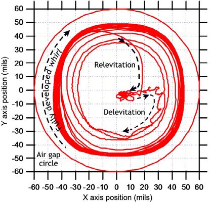
Behavior of the rotor on the backup bearings was       noteworthy in that it implies that the orbit size while
thus demonstrated experimentally. Delevitation tests        whirling is bounded, in this case to a value less than the
were performed at speeds between 10 and 5000 rpm,           radial bearing air gap of 0.060” (1.52 mm). Were the
dropping the rotor onto the backup bearings and             whirl rate to continue increasing for drops at higher
allowing whirl motion to reach steady state.                speeds, the correspondingly larger orbit (eccentricity)
Unexpectedly, in all cases the rotor whirled forward (in    would result in higher centrifugal loads and shaft
the direction of rotation) around the 0.020” radial (0.5    deflection, eventually causing contact between the
mm) backup bearing clearance circle. Reverse whirl          bearing laminations and stator.
was never seen while operating on the backup bearings.
Typical orbit diameter is less than 2 mils during normal                                               Summary of Drop Tests 500 - 5000 RPM
operation. Figure 3 shows an X-Y orbit plot of a                                            30.0                                                                  60

delevitation and relevitation at 2000 rpm (note direction
of shaft rotation is clockwise).                                                            25.0                                                                  55

                                                             Steady State Whirl Rate (Hz)

                                                                                                                                                                       Whirl Orbit Radius (mils)
                                                                                            20.0                                                                  50

                                                                                            15.0                                   Whirl Rate (Hz)                45
                                                                                                                                   Whirl Orbit Radius (mils)

                                                                                            10.0                                                                  40

                                                                                             5.0                                                                  35

                                                                                             0.0                                                                  30
                                                                                                   0    1000     2000       3000            4000           5000
                                                                                                               Shaft Speed at Drop (RPM)

                                                                                            Figure 4. Whirl rates and orbits exhibited through drop tests

                                                                 In an attempt to explain the cause of forward whirl,
                                                            and the natural plateau of the whirl rate, an extensive
                                                            literature search of backup bearing drop tests was
                                                            conducted. First note that backup bearing contact is
                                                            excluded as a cause for forward whirl by Maslen’s
                                                            comment that whirl induced by contact friction can only
                                                            be reverse whirl [7] as friction acts in the direction
        Figure 3. Bearing orbit during 2000 rpm drop test
                                                            opposite to rotation. According to Schmied, [8] the
     For these tests, delevitation was achieved by          cause of forward whirl while operating on backup
ramping the controller gains to zero. Upon this action,     bearings is running with a large imbalance. Swanson
the rotor contacts the backup bearings in about 250 ms.     [9] took this point further by correlating the amount of
Forward whirl begins immediately and takes about 5-6        imbalance with the resulting whirl direction and rates
orbits to fully develop. At shaft speeds up to 1500 rpm,    for horizontal rotors. In these drop tests, large
the forward whirl rate was slightly sub-synchronous         imbalances were necessary to cause forward whirl on
(98-99%). For speeds from 1500 to 5000 rpm, the             ball bearings or solid bushings; the balanced rotors (or
steady state forward whirl rate reached a plateau of 28.3   only slightly imbalanced) did not whirl at all. Further,
Hz (1698 cpm). Multiple drop tests were performed at        Kirk [10] notes that during a drop, the outward spiraling
each shaft speed, and both the whirl rate and orbit size    action of a rotor accelerating toward the backup
exhibited were consistent and repeatable. Figure 4          bearings through the clearance distance provides added
summarizes the whirl rate and orbit size obtained at the    momentum to forward whirl. From these studies, it is
numerous speeds of the drop tests.                          apparent that forward whirl on backup bearings can be
     The size of the orbit of the rotor was measured at     excited by imbalance, or the spiraling that occurs
the radial bearing locations by the collocated optical      during the delevitation before the backup bearings are
position feedback sensors. Due to flexibility of the        engaged.
shaft and deflection of the squeeze film dampers, the            While imbalance may indeed be a general cause of
rotor orbit during whirling is significantly larger than    forward whirl, the ALPS rotor was dynamically
simply the backup bearing clearance, but less than the      balanced in two planes before operation, trimming the
actuator air gap.                                           inertial center to within 0.1 mils of the rotational center,
     A significant conclusion drawn from the drop tests     suggesting that another mechanism may drive forward
is that the forward whirl rate of the rotor operating on    whirl in this application.
the backup bearings is naturally limited to less than 30         Only Kirk and Swanson’s work [9] was found to
Hz, apparently independent of shaft speed. This is          identify specific forward whirl rates. While these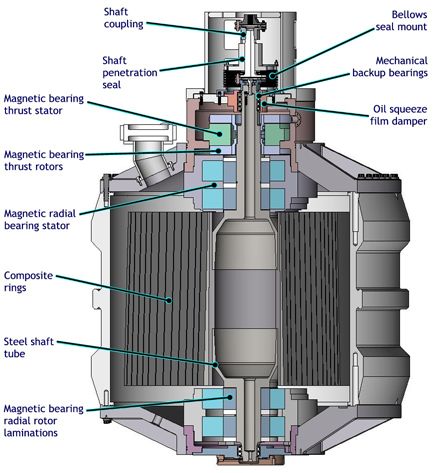
results repeatably demonstrated sub-synchronous                  whirling), or in the variation of the phase relationship
forward whirl for a number of different drop cases, they         between the rotor and housing at various shaft speeds.
are all presented for the same operating speed (4000                  During the course of drop testing, no cases of 44
rpm). It is therefore unclear if the sub-synchronous             Hz whirl were exhibited. Indeed, no whirl rates were
whirl rates were limited or independent of speed.                seen above 28 Hz whatsoever, despite the fact that
     There is however, a very clear consensus in the             several tests were conducted at rotor speeds above 44
literature regarding the determining factor of reverse           Hz. Specifically, the 3000 rpm (50 Hz), 4000 (66.7
whirl frequency. Foiles [11], Fumagalli [12], Maslen             Hz), and 5000 (83.3 Hz) drop tests all locked into the
[7], Ishii [13], and Bartha [14] all mention that for a          27-28 Hz whirl rate. This point is significant in that it
compliantly supported bearing stator, the theoretical            appears to indicate that the 24 Hz conical mode
and experimental results show that reverse whirl                 dominates over the 44 Hz lateral mode (and other, less
quickly “locks in” to the first elastic eigenfrequency of        pronounced, higher frequency modes) with regard to
the combined rotor/stator system (with bearing                   dictating whirl rate. This suggests that the whirl rate is
clearance dead band omitted). Although reverse whirl             likely limited to 28 Hz for drops at all speeds above
is theoretically bounded only by the kinematic rolling           5000 rpm as well.
condition (an extremely high frequency), in application               Confirmation of the theory of the conical housing
the natural frequency of the rotor/stator system strongly        mode determining the maximum whirl rate may be
determines and limits the reverse whirl rate. Bartha             obtained during future testing of the flywheel while
[14] presents a theoretical method to predict maximum            mounted in a two axis gimbal mount. The gimbal
(reverse) whirl rate vs. rotational frequency and                mount and the associated shock isolation system are
compares it to experimental results, yielding excellent          required to minimize gyroscopic and shock loads due to
agreement.       These results demonstrate that the              locomotive chassis motions during dynamic testing.
maximum whirl rate is bounded and occurs at an                   When the mount properties are altered, the housing
intermediate rotor speed and drops slightly with                 natural frequency will be modified, and a corresponding
increased speed. Applying this behavior to the case of           change in the maximum whirl rate is expected. In order
forward whirl, we can postulate that once forward whirl          to isolate the flywheel from the locomotive vibration
momentum is established, a combined rotor/housing                environment, the shock isolation system is targeted with
system mode will also control the forward whirl rate.            a natural frequency of 15 Hz, implying that for the final
                                                                 installation, the maximum whirl rate may be in the
                                                                 neighborhood of 15 Hz.

                                                                 SEMI-PASSIVE WHIRL ARREST
                                                                      In addition to empirical and analytical
                                                                 characterization of rotor dynamic behavior on the
                                                                 touchdown bearings, a semi-passive whirl arresting
                                                                 scheme was devised and tested to allow the operators to
                                                                 manually stop whirling motion during a magnetic
                                                                 bearing fault. This system is useful because sustained
                                                                 whirling operation for prolonged periods is undesirable,
                                                                 regardless of whirl rates and orbit size.
                                                                      Higher loading on the shaft and backup bearings
    Figure 5. Rigid body housing modes identified by rap tests   (reducing bearing life) is one reason to avoid sustained
                                                                 whirling. Also, the whirling action of the rotor in the
     This working theory suggests that a system mode             permanent magnet bias field of the actuator can
may be responsible for limiting the maximum forward              generate undesirable back EMF, predictable by the
whirl rate of the ALPS flywheel to approximately 28              equation for the voltage across the coil of a bearing
Hz. With the rotor supported on the backup bearings,             actuator [15]. This unanticipated phenomenon occurred
rap tests of the flywheel housing in the spin test mount         during some drop tests while whirling at approximately
pedestals identified two rigid body housing modes with           27 Hz. Back-EMF in the system freewheeled through
shapes as shown in Figure 5. The close vicinity of the           the power amplifiers and overcharged the power supply
24 Hz housing mode to the 28 Hz whirl rate plateau               capacitors, causing built-in protection features of the
suggests that this mode is likely dictating the whirl rate       power amplifiers to “trip-out". Relevitation could not
of the rotor on the backup bearings.            Plausible        take place until the over voltage was dissipated. Thus,
explanations for modification of this mode from 24 to            to enhance system reliability by improving the chances
28 Hz may exist in nonlinearity of the system at large           of being able to relevitate after a drop, additional
deflections (as those experienced during large orbit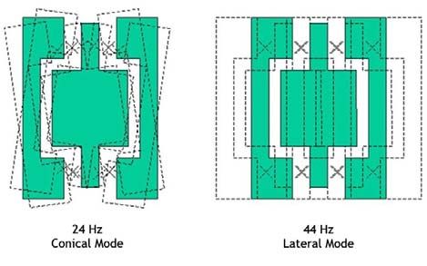
devices were added to the magnetic bearing power The current required to stop whirl was found to increase
electronics to shunt regenerative currents. as speed increased, eventually requiring 5 amps at 2000
A further reason to arrest whirl in the ALPS rpm (25% of maximum dynamic radial bearing current
flywheel system is that the dynamic load capacity of the for this system). Further testing at speeds up to 5000
radial bearings is marginal for re-centering the rotor rpm, demonstrated that 5 amps was sufficient to arrest
from large orbits at about 30 Hz (while the forward fully developed whirl. It is believed that the required
whirl rate is limited to approximately 28 Hz). current does not continue to increase as speed increases
Therefore, the ability to re-center the rotor after because the whirl rate was found to remain essentially
clearing a magnetic bearing fault is much improved if capped at close to 28 Hz.
the rotor is captured rather than whirling.
Many works [10,11,12,16] demonstrate the
theoretical and experimental effectiveness of the gravity
field in preventing whirl (both forward and reverse) in
horizontal rotor systems. The cause for this [12] is that
the energy converted to reverse whirl through friction
(minus the whirl energy dissipated in the backup
bearing dampers) can be insufficient to overcome the
potential energy required to lift the rotor out of the
bottom half of the backup bearing orbits.
Although the ALPS rotor is vertical, this same
principle of a “gravity” field was synthetically applied
to arrest whirl. By generating a preferred radial
orientation of the rotor through a DC bias field created
by the control coils, a similar effect is imposed on the
rotor. With this approach, the rotor is pulled
preferentially into a particular radial quadrant, and a
potential energy well is produced which arrests the
whirling rotor.
A manually switched passive whirl arresting circuit
was created and installed in the magnetic bearing
cabinet. The action replaces the command inputs from
the active magnetic bearing (AMB) compensator to the
power amplifiers with fixed (but adjustable) constant
current commands, as shown in Figure 6.
Passive Manual Manual disable
command command switch input
circuit (whirl selector switch
arresting)
Amps Plant
DSP
Active
compensator
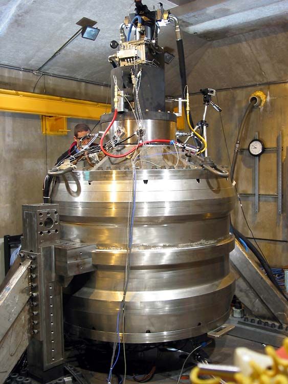
Figure 7a-f. Dropping, arresting, and relevitating rotor at 5000 rpm
Figure 6. Whirl arrest schematic Figures 7a-f show the operation of the whirl arrest
circuit capturing the rotor during a 5000 rpm drop test.
The passive current command result in a force For this experiment, the rotor was delevitated
pushing the rotor into the +X,+Y quadrant of both intentionally by the magnetic bearing controller, and
radial bearings. By influencing the rotor to stay in one whirl was allowed to fully develop before activating the
quadrant, this circuit has been shown to arrest the whirl arrest circuit. The circuit has the immediate
whirling rotor within a few whirl cycles, at all drop test effect of influencing the orbit shape to non-circular, and
speeds. The semi-passive whirl arrest circuit may after 3-4 whirl cycles (150 ms), holding the rotor
provide protection against whirling in the case of a fault steadily against the backup bearings in quadrant 1. The
of the bearing controller, loss of a position sensor, or rotor is then dropped again onto the backup bearings,
possibly loss of amplifiers (if a sufficiently high DC allowing whirl to fully develop, then relevitated to
current level is used on the remaining amplifiers). center. Note, one second of time data is shown in each
Testing of the whirl arrest system began at 500 rpm plot.
where it was found that a minimum of 1.2 amps of An extremely significant point regarding the whirl
current was required to arrest fully developed whirl. arrest behavior is the angular location at which the rotorsettles after being captured. When using the whirl high frequency reverse whirl in magnetically supported
arrest at rest, the rotor pulls directly toward the 45° rotors operating on their backup bearings. Future drop
position in quadrant 1 (indicated by the dashed line in simulations will incorporate a forward driving force due
Figure 5). However, at 5000 rpm, the lock in position to damping in the rotating assembly to attempt to
leads the 45° line by an angle θ, of approximately 30°. replicate the behavior observed during the drop
This fact indicates that there is a constant, forward experiments.
directed force which opposes and exceeds that of the The theory of lamination frictional damping
backup bearing drag. As summarized in Table 1, this driving forward whirl can be tested by “bias field
phase angle does not vary significantly with drop speed, cancellation”, an alternative whirl arrest method that
suggesting that the rise of the forward acting force is was conceived, but not yet attempted. As the
essentially balanced with the rise of the retarding permanent magnet bias increases deflection in the
bearing drag. lamination region of the shaft (and therefore damping
force magnitude), reducing the bias field should
Table 1. Summary of arrested position of spinning rotor
Shaft Speed Arrest Current Thrust End Bearing Arrested Position
decrease the tendency to forward whirl. By passively
ω at Drop (rpm) (dc A) r Radial Position (mils) θ Lead Angle (°) reducing or canceling the radial bearing permanent
500 1.2 41.4 40.3
1000 1.75 41.1 42.4 magnet bias field through commanding opposing dc
1500 4 41.8 34.0 currents in the control coils, the rotor is expected to
2000 5 42.9 31.8
2500 5 42.7 31.9 transition from forward whirl to reverse whirl while on
3000 5 42.4 28.0 the backup bearings. By selecting the appropriate level
4000 5 41.6 28.5
5000 5 39.9 29.6 of bias field cancellation current, the forward whirl
force may be reduced to the point that it balances
The demonstration of a forward acting force is against the backup bearing drag, resulting in zero whirl.
important as it is likely the root cause of forward whirl
in this rotor. A possible explanation for the origin of FUTURE WORK
this forward acting force is damping in the rotating Upon completion of the endurance tests in
assembly [17]. The radial bearing lamination stacks progress, an accurate characterization of the magnetic
provide an obvious potential source of damping in the bearing losses will be performed by integrating the
sliding frictional interfaces between the individual experimental temperature data with the thermal analysis
laminations. model. In parallel, commissioning and tuning to full
Due to the particular geometry of the ALPS speed will be performed over the coming weeks, thus
flywheel rotor, the radial bearing permanent magnet concluding intermediate spin testing.
bias force not only presses the rotor against the backup The next phase of ALPS flywheel testing will take
bearings, but also induces a large bending moment in place after the remaining composite rings are installed,
the bearing lamination area of the shaft, likely building the rotor to its final 5100 lb form. The full
exacerbating frictional damping between the rotor, full power testing with the motor generator will
laminations. The rotor lamination areas are in fact be performed first statically in the laboratory, before
located in the large deflection regions of the shaft, integration into the locomotive. The dynamic
where any damping effect would be most significant. demonstration of the complete ALPS power system in
The main body of the rotor, with its large composite locomotive operation on a test track is currently
structure, may also be a source of damping specific to scheduled for the 4th quarter of 2005.
the ALPS rotor, although this is not a region of large
deflection. It should be noted that the amount of ACKNOWLEDGEMENTS
damping required for this theory is not necessarily high, This material is based upon work supported by
only enough to dominate over the relatively low Federal Railroad Administration cooperative
rotational drag of the ball backup bearings. agreement, DTFR53-99-H-00006 Modification 4, dated
High internal damping in the rotor lamination April 30, 2003. Any opinions, findings, and
stacks is a theory that may explain the rotor’s tendency conclusions or recommendations expressed in this
to forward whirl, rather than to reverse whirl, as publication are those of the authors and do not
exhibited by many smaller, rigid rotors. Perhaps the necessarily reflect the view of the Federal Railroad
ALPS rotor’s ratio of relatively high internal shaft Administration and/or U.S. DOT.
damping and relatively low backup bearing drag The authors would also like to acknowledge the
provide the necessary conditions for forward whirl on numerous colleagues and partners who have made
the backup bearings. Therefore, perhaps a flexible rotor contributions to the development of the ALPS flywheel,
with a relatively high amount of internal shaft damping without which these experiments would not have been
(which is traditionally avoided in conventionally possible. Recognition goes in particular to CEM
supported rotors) is actually desirable in preventing engineers Doug Wardell, Carl Graf, and Jim Upshawfor engineering the control and instrumentation [10] Kirk, R.G., Ishii, T., “Transient Rotor Drop
equipment of the experiments, overseeing the Analysis of Rotors following magnetic bearing Power
composite ring fabrication, and carrying out the precise Outage,” UVA MAG 1993.
assembly of the flywheel components, respectively. [11] Foiles, W.C., Allaire, P.E., “Nonlinear Transient
Special appreciation is given to former CEM employee Modeling of Active Magnetic Bearing Rotors during
Bobby Sledge for his many years of diligent design and Rotor Drop on Auxiliary Bearings,” UVA MAG 1997.
fabrication work on the flywheel. Larry Hawkins of [12] Fumagalli, M., Schweitzer, G., “Motion of a Rotor
Calnetix deserves thanks for his excellent work in in Retainer Bearings,” ISMB 1996.
designing an AMB compensator to integrate with
existing hardware. Finally, gratitude is offered to Dr. [13] Ishii, T., and Kirk, R.G., “Transient Response
Alan Palazzolo and his VCEL group at Texas A&M technique Applied to Active Magnetic Bearing
University for their work in simulating and optimizing Machinery During Rotor Drop,” ASME Biennial 1991.
the actuator design for controllability, and support [14] Bartha, A.R., “Dry Friction Backward Whirl of
during early flywheel commissioning. Rotors: Theory, Experiments, Results, and
Recommendations,” ISMB 2000.
BIBLIOGRAPHY [15] Hawkins, L.A., Flynn, M., “Influence of Control
Strategy on Measured Actuator Power Consumption in
[1] Herbst, J.D., Caprio, M.T., Thelen, R.F., “Status of an Energy Storage Flywheel with Magnetic Bearings,”
the Advanced Locomotive Propulsion System (ALPS) 6th International Symposium on Magnetic Suspension
Project,” 2003 ASME International Mechanical Technology, October 7-11, 2001, Torino, Italy.
Engineering Congress & Exposition (IMECE ’03), [16] Kirk, R.G., Ishii, T., “Analysis of Rotor Drop on
November 16-21, 2003, Washington D.C. Auxiliary Bearings Following AMB Failure,” UVA
[2] Caprio, M.T., Herbst, J.D., Thelen, R.F., “2 MW MAG 1991.
130 kWh Flywheel Energy Storage System,” Electrical [17] Black, H.F., “The Stabilizing Capacity of Bearings
Energy Storage Applications and Technology for Flexible Rotors with Hysteresis,” ASME Paper No.
(EESAT2003), October 27-29, 2003, San Francisco, 75-DET-55, Design Engineering Technical Conference,
CA. Washington D.C., September 1975.
[3] Thelen, R.F., Herbst, J.D., Caprio, M.T., “A 2MW
Flywheel for Hybrid Locomotive Power,” IEEE Additional references reviewed but not cited
Semiannual Vehicular Technology Conference, [18] Ramesh, K., Kirk, R. G., “Rotor Drop Test Stand
October 6-9, 2003, Orlando, FL. for AMB Rotating Machinery Part II: Steady State
[4] Murphy, B.T, Ouroua, H., Caprio, M.T., Herbst, Analysis and Comparison to Experimental Results,”
J.D., “Permanent Magnet Bias Homopolar Magnetic ISMB 1994.
Bearings for a 130 kW-hr Composite Flywheel,” [19] Raju, K.V.S., Ramesh, K., Swanson, E.E., Kirk,
ISMB-9, August 3-6, 2004, Lexington, KY. R.G., “Simulation of AMB Turbomachinery for
[5] Fumagalli, M.A., Modelling and Measurement Transient Loading Conditions,” UVA MAG 1995.
Analysis of the Contact Interaction between a High [20] Tessier, L.P., “The Development of an Auxiliary
Speed Rotor and its Stator, Dissertation ETH No. Bearing Landing System for a Flexible AMB-
12509, Swiss Federal Institute of Technology, Zurich, Supported Hydrogen Process Compressor Rotor,” UVA
1997. MAG 1997.
[6] Bartha, A.R., Dry Friction Backward Whirl of [21] Ecker, H., “Steady-State Orbits of an AMB-
Rotors, Dissertation ETH No. 13817, Swiss Federal Supported Rigid Rotor Contacting the Backup
Institute of Technology, Zurich, 2000. Bearings,” UVA MAG 1997.
[7] Maslen, E.H., Barrett, L.E., “Feasible Whirl of [22] Feeny, B., Fumagalli, M., Schweitzer, G.,
Rotors in Auxiliary Bearings,” UVA MAG 1995. “Dynamics of Rigid Rotors in Retainer Bearings,”
[8] Schmied, J., Pradetto, J.C., “Behaviour of a one ton ISMB 1992.
Rotor Being Dropped into Auxiliary Bearings,” ISMB [23] Dell, H., Engel, J., Faber, R., Glass, D.,
1992. “Developments and Tests on retainer Bearings for
[9] Swanson, E.E., Kirk, R.G., Wang, J., “AMB Rotor Large Active Magnetic Bearings,” ISMB 1988.
Drop Initial Transient on Ball and Solid Bearings,”
UVA MAG 1995.You can also read