USER'S MANUAL ATH-Flex Lift
←
→
Page content transcription
If your browser does not render page correctly, please read the page content below
USER’S MANUAL
ATH-Flex Lift

® Urheberrecht ATH-Heinl GmbH & Co. KG, 2017, Alle Rechte vorbehalten. / Druckfehler und technische Änderungen vorbehalten / Stand: 04/2017
                                                                    1
CONTENT

INTRODUCTION .............................................................................................................................................. 3
   General information ....................................................................................................................................... 3
   Description .................................................................................................................................................... 4
   Operation ...................................................................................................................................................... 5
   Technical data ............................................................................................................................................... 6
   Scope of delivery ........................................................................................................................................... 8
INSTALLATION ................................................................................................................................................ 8
   Floor foundation ............................................................................................................................................ 8
   Place of installation........................................................................................................................................ 9
   Installing ...................................................................................................................................................... 10
OPERATION ................................................................................................................................................... 12
   Safety instructions ....................................................................................................................................... 12
   Operation instruction ................................................................................................................................... 14
MAINTENANCE .............................................................................................................................................. 15
   Troubleshooting ........................................................................................................................................... 15
   Maintenance plan ........................................................................................................................................ 17
   Lubrication plan ........................................................................................................................................... 17
DECLARATION OF CONFORMITY ................................................................................................................ 20
SPARE PART LIST ......................................................................................................................................... 21
ANHANG ........................................................................................................................................................ 34
   Elektro-Schaltplan ....................................................................................................................................... 34
   Elektro-Schaltplan ....................................................................................................................................... 35
WARRANTY CLAIM........................................................................................................................................ 36
CHECKING BOOK .......................................................................................................................................... 38
NOTES ........................................................................................................................................................... 51

  ® Urheberrecht ATH-Heinl GmbH & Co. KG, 2017, Alle Rechte vorbehalten. / Druckfehler und technische Änderungen vorbehalten / Stand: 04/2017
                                                                                  2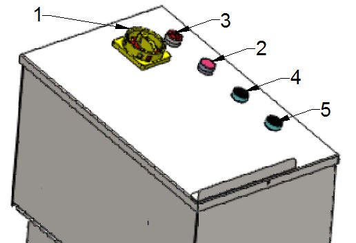
INTRODUCTION

General information

                  THE USER OF THE LIFT HAVE TO READ AND UNDERSTOOD THIS MANUAL.
         ALL LIABILITY IS EXCLUDED FOR DAMAGES WHICH RESULT FROM NON-COMPLIANCE OF THIS
                                           INSTRUCTIONS.
         WE WILL NOT ASSUME ANY LIABILITY CAUSED BY NON-COMPLIANCE WITH SAFETY DEVICES:

        ATTENTION: Follow the instructions to prevent personal injury or damage

        TIP: Gives additional information on features and tips for efficiently using of the device.

 ® Urheberrecht ATH-Heinl GmbH & Co. KG, 2017, Alle Rechte vorbehalten. / Druckfehler und technische Änderungen vorbehalten / Stand: 04/2017
                                                                     3
Description

   1.   Platform
   2.   Scissor arm
   3.   Base frame
   4.   Hydraulic cylinder
   5.   Hydraulic unit with control
   6.   Safety rail
   7.   Transport kit

 ® Urheberrecht ATH-Heinl GmbH & Co. KG, 2017, Alle Rechte vorbehalten. / Druckfehler und technische Änderungen vorbehalten / Stand: 04/2017
                                                                     4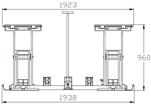
Operation

   1. Lockable main switch with emergency stop function
      For switching on and off and prevents a switching on/off from unauthorized persons.

   2. Signal lamp
      Indicates whether the lift is in stand-by.

   3. Buzzer
      Gives an acoustic and visual signal after reaching the CE-Stop.

   4. Push button lifting
      For lifting

   5. Push button lowering
      For lowering

 ® Urheberrecht ATH-Heinl GmbH & Co. KG, 2017, Alle Rechte vorbehalten. / Druckfehler und technische Änderungen vorbehalten / Stand: 04/2017
                                                                     5
Technical data

 ® Urheberrecht ATH-Heinl GmbH & Co. KG, 2017, Alle Rechte vorbehalten. / Druckfehler und technische Änderungen vorbehalten / Stand: 04/2017
                                                                     6
Type ATH-Flex Lift 30
Capacity 3000 kg
Lifting time (at 2.000 kg) 20 s
Lowering time (at 2.000 kg) 28 s
Electrical system 1 X 230V/50Hz
Control voltage DC24V
Motor 2,237 KW / 1450 Rpm
Fuse protection 3 C 16 A
Power cable Min. 3x 1,5mm²
Protection class IP 43
Hydraulic pressure ² 150-300 bar
Summer: H-LPD 32 (z.B.: OEST H-LPD 32 DD L)
Recommended hydraulic oil
Winter: H-LPD 22
Oil quantity Appr. 12 l
Noise level ≤ 70 dB
Weight 540 kg
² The already factory-set hydraulic work pressure is adjusted to the maximum rating. The setting of the pressure
control valve may not be changed. Any changes to the settings could cause serious damages.
If the nominal load could be not lifted please contact our service team.
Load distribution
Q Total weight of vehicle
P1 Max 3/5 x Q
P2 Max 2/5 x Q
Load disctribution 3/2
A 1.200 mm
² By changed distances the load capacity will be reduced.
® Urheberrecht ATH-Heinl GmbH & Co. KG, 2017, Alle Rechte vorbehalten. / Druckfehler und technische Änderungen vorbehalten / Stand: 04/2017
7Scope of delivery
1 Basic package with:
• Scissor lift with already integrated hydraulic cylinders
Dimension:
Weight: 500 kg
2 Control with:
• Integrated hydraulic aggregate
• User’s manual with checking book
Dimension:
Weight: 50kg
If there is anything missing in the scope of delivery please contact our sales department!
Instructions for transport and storage:
- Lift with care, support the load with means which are suitable and in good order and condition.
- Avoid sudden raisings and jerky movements. Be careful at floor unevenness, cross-drain etc.
- Store the removed packing at a collecting place until disposal, so that they are not accessible for children or animals.
- Storage temperature: -10~+40 °C
INSTALLATION
Floor foundation
Requirements: horizontal and even
Concrete thickness: 200 mm
Max. gradient: 10 mm
Concrete quality: C20/25
Concrete curing time: Min. 20 days
If soils do not comply with the requirements, there could evoke serious injuries to personal or damages to the lift.
Do not install the lift on asphalt, soft concrete floor etc.
The capacity of intermediate ceilings must be checked by the operator.
® Urheberrecht ATH-Heinl GmbH & Co. KG, 2017, Alle Rechte vorbehalten. / Druckfehler und technische Änderungen vorbehalten / Stand: 04/2017
8Place of installation
A1 Min. 2.000mm A2 Min. 700 mm
B1 Min. 700 mm B2 Min. 1.000 mm
Admitted working temperatures: -10/+50 °C
Max. admitted air humidity: ≤80% bei 30 °C
Hight over sea level: ≤2000m
Electrical connection & ground cable (see tecnical data) can be made with a plug connector (socket and plug device) or a
fixed connection.
Necessary supply lines: See technical data
It MUST exist an emergency exit of min. 700 mm, also during a vehicle is lifted.
The installation in wet rooms as well as rooms with a risk of explosion is not allowed.
® Urheberrecht ATH-Heinl GmbH & Co. KG, 2017, Alle Rechte vorbehalten. / Druckfehler und technische Änderungen vorbehalten / Stand: 04/2017
9Installing
This manual is not to be seen as an assembly instruction, it gives only advices and help for skilled personal.
For the following works are to be weared adequate clothes and individual safeguardings.
An incorrect installation and adjustments causes disclaimer of warranty
1. Positioning and adjustment of the lift and control box
2. Connection of hydraulic tubes
a. Carry the hydraulic tubes through the enclosed empty tube
b. Fix the tubes on the connections of the scissor lift and on the Y-connection on the control box.
Retighten all hydraulic connections.
3. Hydraulic oil
a. Fill in the hydraulic oil until the marking on the dipstick
b. For venting of the hydraulic circuit leave the tank cap open for the first 10 lifting movements.
4. Electrical connection
Hereby must be observed the general and local regulation. Therefore, this step can only be done only by
trained/skilled persons/experts.
Pay attention to the necessary supply (see technical data).
5. Install the ramps with locking’s on the scissor lift.
® Urheberrecht ATH-Heinl GmbH & Co. KG, 2017, Alle Rechte vorbehalten. / Druckfehler und technische Änderungen vorbehalten / Stand: 04/2017
106. Control before the first lifting
a. all screws, nuts and so on for tightness
b. all connections and cylinders for leaks and retighten them if necessary
c. the oil level
d. all electrical connections (see electric diagram) as well as the ground cable
e. that the hydraulic system will be vented completely by lowering the lift completely and pushing for appr.
15 seconds the button lowering further.
f. the function of the limit switch
g. that the sliding guides of the base frame and the platform are lubricated (see lubrication plan)
7. Lifting under load
a. Lift a load to appr. 500 mm height
b. Check that all the mounting points are in contact with the vehicle. If all points are in contact with the car,
the stage is straight.
8. Fill in after installing the enclosed checking book.
This information will be required in case of a possible claim.
® Urheberrecht ATH-Heinl GmbH & Co. KG, 2017, Alle Rechte vorbehalten. / Druckfehler und technische Änderungen vorbehalten / Stand: 04/2017
11OPERATION
Safety instructions
1. Take care of a correct load
distribution of the vehicle
2. Changes of any kind on the lift are
not allowed
3. Leave the danger zone while
lowering the lift
4. It is not allowed to carry objects or
persons on the lifting arm resp. on
the lifted vehicle.
5. In case of danger that vehicle will
fall down leave immediately the
danger zone.
6. Avoid too much swivel movements
on the lifted vehicle
7. Lift may only be operated by skilled
personal.
8. Use a suitable roll protection
9. Only authorized persons are
allowed to enter the danger zone.
10. A proper maintenance and
inspection are necessary for a safe
work
11. Read and understood the user´s
manual before operating the lift
12. Do not work on defect lifts
13. Keep shearing points free while
moving the lift
14. Do not clean the lift under running
water.
15. While lifting and lowering the
danger zone must be keep free.
® Urheberrecht ATH-Heinl GmbH & Co. KG, 2017, Alle Rechte vorbehalten. / Druckfehler und technische Änderungen vorbehalten / Stand: 04/2017
12BTR-Nr. 0030 Operating instructions Stand: Dezember 2010
18.12.2012 Scope and activities abgezeichnet am: 10.12.2012
SCOPE OF APPLICATION
Vehicle lift
RISKS TO PEOPLE AND THE ENVIRONMENT
• Crushing point during the moving of the vehicle and/or parts
• Pinching - und shearing places during the moving of the vehicle and/or parts
• With a leaking system hydraulic oil can enter into the environment
PROTECTIVE MEASURES AND DIRECTIVES
• This User’s manual must be observed
• The lift have to be observed
• Operation only by trained personnel
• Pinching - und shearing places its surroundings
• Check the correct load capacity and load distribution of vehicles
• Secure vehicle against movement
• Daily perform a function test before starting
• Clear area if vehicle is in danger of falling
• No person carrying on the lift
• Keep free the area by lifting or lowering of the vehicles
BEHAVIOR IN THE EVENT OF FAILURE AND DANGER
• By any related operation incidents the lift have to secured and ensure for any
use
• Inform supervisors in case of defects
• Deficiencies can only be removed by the specialist
ASSISTANCE IN ACCIDENTS – FIRST AID
• Secure the scene of an accident
• First aid assistance have to keep informed the rescuer ________________
• and supervisors ________________
• Take care of the casualties.
• Place of the first aid kit and first aid book : ________________
• EMERGENCY CALL ________________
• Records all the information in the first aid book
MAINTENANCE, DISPOSAL
® Urheberrecht ATH-Heinl GmbH & Co. KG, 2017, Alle Rechte vorbehalten. / Druckfehler und technische Änderungen vorbehalten / Stand: 04/2017
13• Repair services of lift are performed by:
________________
• Waste disposal (For example used oil) is responsible: ________________
Operation instruction
The product is intended for lifting of vehicles the respective technical data of the lift have to be attended.
1. Placing of lift
a. Push the button „lifting“ to be able to install both rolls of the moving set. Take care that they are in the
correct position on the crossbeam.
b. Lower the lift completely with the button „lowering“, thereby the back part of the lift places automatically
on the rolls.
c. Place the front adapter of the drawbar on the lift.
d. Position the control box on the platform and fix it if necessary while moving the lift.
e. Lock the ramps.
f. Now you can lift in front the lift with the drawbar and move the lift. Pay always attention to the control box.
g. Place the lift at a suitable location.
h. For placing the lift ready for operation follow the items a. – g. in reverse order.
2. Preparation
a. Read all safety instructions carefully before operating the lift.
b. Control of the ground clearance of the vehicle.
c. Place the vehicle central to the lift and drive on. Take care of the load distribution.
d. Place the suitable rubber disks on the platform of the lift. Pay attention that those are central under the
lifting points of the vehicle.
3. Lifting
a. Switch on the lift with the main switch
b. Lift the vehicle until a height of 100-150mm and stop the lifting by releasing the button “Lifting”.
c. Check if the vehicle stands safely on the lift and that the safety notches are activated.
d. Following lift further and observe the lifting process.
4. Lowering
a. Before lowering check if there are objects under the vehicle or the lift.
b. Press the lowering button, the lift will lift a few seconds, unlock the notches and then lowers
5. Termination
a. Remove the rubber disks from the lift.
b. Drive the vehicle off the lift.
® Urheberrecht ATH-Heinl GmbH & Co. KG, 2017, Alle Rechte vorbehalten. / Druckfehler und technische Änderungen vorbehalten / Stand: 04/2017
14MAINTENANCE
Maintenance and repair works are only allowed to be done by authorized service partners or, after consulting ATH, by the
customer...
Before any maintenance and repair works the lift have to be disconnected from the power supply (main switch off,
disconnection of main plug). Make sure that a reconnection of the powers supply cannot occur.
Only skilled persons/experts are allowed to work on the electrical part of the lift respectively on the supply.
Troubleshooting
Symptoms Reason Troubleshooting
Problems while lifting
Check the motor and replace if
Defects on the motor
necessary
Blown fuses because of e.g. voltage Eliminate the cause and replace
fluctuation fuses
Defect button and/or contact Replace button and/or contact
Lift does not raise when pressing the
Defect main switch and/or contact Replace main switch and/or contact
button (motor doesn´t work)
Defect or insufficient supply line Replace cable
Fluctuating or not enough voltage Control voltage
Defect contactor Replace contactor
Thermal relay has activated Check thermal relay and motor
Mainboard defect Check mainboard
Hydraulic oil deficiency Refill oil
Oil filter blocked Clean oil filter
Oil loss Replace defect parts
Check and replace if necessary the
Opened lowering valve
lowering valve
Lift does not raise when pressing the
False sense of rotation of the motor Change phases
button (motor does work)
Check the pump and replace it if
Defect gear pump
necessary
Admitted capacity was exceeded Work within the indicated capacity
Adjust relief valve to the max.
Relief valve was adjusted too low
capacity
Air in hydraulic system Bleed the hydraulic system
Lift raise jerkily Dirty hydraulic oil Change the hydraulic oil
Sliding guide are not lubricated Lubricate the sliding guide
Lift raise after releasing the button
Defect button Replace the defect button
further
® Urheberrecht ATH-Heinl GmbH & Co. KG, 2017, Alle Rechte vorbehalten. / Druckfehler und technische Änderungen vorbehalten / Stand: 04/2017
15Problems while lowering
Mainboard defect Check mainboard
Object under the lift Remove object
Raise lift shortly, and push „DOWN“
Excess flow cutoff activated
again
Lowering valve will not be activated Check electrical connections
Lift does not lower Magnet coil of lowering valve defect Replace magnet coil
Raise lift shortly, and push „DOWN“
Excess flow cutoff activated
again
Lowering valve defect Replace it
Valve for lowering speed false
Adjust
adjusted
If the error cannot be found, lower the lift by using the emergency lowering screw and notify our Service.
Valve for lowering speed false
Adjust
adjusted
Lift lowers to slowly or jerky
Retighten and if necessary seal the
Leaking hydraulic connections
hydraulic connections
Leaking hydraulic hoses Replace hydraulic hoses
Replace seals and clean hydraulic
Leaking hydraulic cylinders
system
Lift lowers by itself Cleaning or replacing the lowering
Dirty or defect lowering valve
valve
Leaking non-return valve Cleaning or replacing
Other problems
Dirty oil filter Clean oil filter
Abnormal noise of motor Air in hydraulic system Bleed hydraulic system
Dirty hydraulic oil Change hydraulic oi
Control the contact at the contactor Replace the contactor
Motor contactor was activated Control capacity of contactor Replace the fuses
Control if cable is defect Replace the cable
® Urheberrecht ATH-Heinl GmbH & Co. KG, 2017, Alle Rechte vorbehalten. / Druckfehler und technische Änderungen vorbehalten / Stand: 04/2017
16Maintenance plan
Intervalls: Components: Examination to:
Rubber pads Wear and Deformation
Lift structure Apparent damages
Daily Lift structure Cleanliness
Hydraulic Leakage
Safety devices Apparent damages
Magnets Function and wear
Weekly
Cylinder Wear
Spindle and bolts Wear and cleaning
Quarterly Locking of ramps Function and cleaning
Cylinder (dust seal) Wear and deformation
Electrical components Damages
Half-yearly
Oil level Shortage
Yearly Cylinder-seal Oil leakage and deformation
Hydraulic oil Change
Every 3 years
(Recommended)
Hydraulic-system Cleaning
Every 6 years Horses Replacing
Lubrication plan
Intervalls: Components: Type of oil resp. grease:
Spindle and bolts Multi-purpose grease
Monthly
Sliding guides Multi-purpose grease
Synchronization ropes Adhesive lubricant
Quarterly
Locking of ramps Lubricate
® Urheberrecht ATH-Heinl GmbH & Co. KG, 2017, Alle Rechte vorbehalten. / Druckfehler und technische Änderungen vorbehalten / Stand: 04/2017
17Maintenance and service instructions
Oil level control
1. Lower the lift completely
2. Remove the tank cap
3. Control the oil level on the dipstick
Oil change
1. Lower the lift completely
2. Remove the tank oil filling plug
3. Remove carefully the oil drain screw and drain the oil in a suitable retainer.
Clean the tank and oil filter to avoid a premature contamination of the hydraulic oil.
4. After the complete oil draining lock the tank with the oil drain screw
5. Fill the new oil into the tank
6. Lift and lower the lift and check, if the maximum lifting height is still correct. If necessary refill carefully.
The used oil must be disposed in accordance with all legal and federal requirements.
Venting of hydraulic system
For bleeding the hydraulic circuit leave the tank cap open for the first 10 lifting movements.
Lower the lift completely and push further for appr. 15 seconds the button Lowering so that the hydraulic system will be
completely. Vented.
Emergency drop in case of power failure
Control Valve Lowering Valve
(104) (103)
1. Turn the emergency lowering screw (103) slowly
counterclockwise and at the same actuate the control valve
several times by hand
2. After completely lowering close the emergency lowering
screw (103) by turning clockwise.
® Urheberrecht ATH-Heinl GmbH & Co. KG, 2017, Alle Rechte vorbehalten. / Druckfehler und technische Änderungen vorbehalten / Stand: 04/2017
18Adjustment of valve for lowering speed
Loosen the counter-screw (1)
Adjust the lowering speed as described in the technical data.
By turning the stud screw (2) clockwise the lift lowers slowly, by turning it counterclockwise the lift lowers faster.
® Urheberrecht ATH-Heinl GmbH & Co. KG, 2017, Alle Rechte vorbehalten. / Druckfehler und technische Änderungen vorbehalten / Stand: 04/2017
19DECLARATION OF CONFORMITY
Seriennummer / Serial number:
Konformitätserklärung
Declaration of conformity
Déclaration de conformité
Declaración de conformidad
Für / for / pour / para Typ / Type / Type / Tipo
KFZ-Hebebühne
Car-lift
ATH-Flex Lift 30
Ponts élévateurs
Elevador
Wurden folgende einschlägige Bestimmungen beachtet
The following EG-directives are considered
2006/42/EC (Machine-Directive)
Les Directives suivantes de l’Union européenne ont été respectées
Los siguientes directivas pertinentes de la Unión Europa fuen cumplido
Folgende harmonisierten Normen und Vorschriften wurden eingehalten
The following harmonized standards are applied DIN EN 1493:2010 (Machine-Directive)
Les normes harmonisées suivantes ont été appliquées DIN EN 60204-1: 2006+A1:2009 (Low voltage directive)
Los siguientes normas y reglamentos armonizados fuen cumplido
Hersteller ATH-Heinl GmbH &Co. KG
Manufacturer Kauerhofer Straße 2
Fabricant D-92237 Sulzbach-Rosenberg
Fabricante Germany
CCQS UK Ltd.,
Prüfinstitut
Institut of Quality
Level 7, Westgate House, Westgate road,
Institut de qualité
London W5 1YY UK
Instituto de calidad
Referenznummer der technischen Daten:
Reference number for the technical data:
TF-C-0519-11-31-04-5A
Numéro de référence des données techniques:
Número de referencia de los datos técnicos:
Typ / Type / Type / Tipo
Herstellerbezeichnung
Designation of producer
ATH-Flex Lift 30
Désignation du producteur
Denominación del fabricante
Nummer des Zertifikats:
Number of the certificate:
CE-C-0519-11-31-04-5A
Numéro du Certificat
Número del certificado
Hiermit wird bestätigt, dass die oben bezeichneten Maschinen den genannten EG-Richtlinien entsprechen.
Herewith we confirm that the above named machines are according to the named EC-directives.
Nous certifions par la présente la conformité des machines décrites ci-dessus aux Directives de l’Union européennes citées.
Confirmamos con esto de que la mercancía denominada arriba cumple las directivas llamadas de la Unión Europea.
ATH-Heinl GmbH &Co. KG
Kauerhofer Straße 2
D-92237 Sulzbach-Rosenberg
Germany
Im Dezember 2016
ATH-Heinl GmbH & Co. KG/ Hans Heinl (Geschäftsführer)
® Urheberrecht ATH-Heinl GmbH & Co. KG, 2017, Alle Rechte vorbehalten. / Druckfehler und technische Änderungen vorbehalten / Stand: 04/2017
20SPARE PART LIST
® Urheberrecht ATH-Heinl GmbH & Co. KG, 2017, Alle Rechte vorbehalten. / Druckfehler und technische Änderungen vorbehalten / Stand: 04/2017
21ITEM ATH PART NO Art. Beschreibung Art. DESCRIPTION Detail QTY REMARK
´01-1 HPR8530 Plattform Rechts Platform Right 1
´01-2 HPL8530 Plattform Links Platform Left 1
´01-3 HDF2028 Lenkstange Steerig rod 1
´01-4 HHA8351.10 Steuereinheit Control unit 1
´01-5 HGA1422 Gummiauflage Rubber Block 160X120X40 4
® Urheberrecht ATH-Heinl GmbH & Co. KG, 2017, Alle Rechte vorbehalten. / Druckfehler und technische Änderungen vorbehalten / Stand: 04/2017
22® Urheberrecht ATH-Heinl GmbH & Co. KG, 2017, Alle Rechte vorbehalten. / Druckfehler und technische Änderungen vorbehalten / Stand: 04/2017
23Art.
ATH PART NO Art. Beschreibung Detail QTY REMARK
DESCRIPTION
ITEM
´01-01 HGP1133 Plattform Links left bottom plate 1
combined
´01-02 HGS3123 Gleitstück unten 2
bearing(lower)
combined
´01-03 HGS3124 Gleitstück oben 2
bearing(upper)
´01-04 HGS3125 Gleitstück aussen lower bearing 2
´01-05 HGP1134 Grundplatte rechts right bottom plate 1
´01-06 HST8255 Scherenteil vorne external armsection 1
´01-07 HST8256 Scherenteil hinten internal armsection 1
´01-08 HGS3126 Gleitstück hinten lower slide block 2
´01-09 HPR8530 Plattform rechts right top plate 1
´01-10 HGS3127 Gleitstück oben upper slide block 4
´01-11 HPL8530 Plattform rechts left top plate 1
support bracket of
´01-12 HRA2031 Lollenträger 3
roller
´01-13 HBS2025 Mittelachse center axle 2
´01-14 HBS2026 Bolzen axle 4
´01-15 HBS2027 Bolzen axle 2
´01-16 HHZ6121 Hydraulikzylinder cylinder 55 4
´01-17 HDF2028 Lenkstange steerig rod 1
´01-18 HBS2029 Bolzen axle 4
´01-19 HAL2030 Rampe Links drive on ramp(left) 2
´01-20 HAR2031 Rampe Rechts drive on ramp(right) 2
´01-21 HRR3426 Rolle roller of ramp 8
´01-22 HBR2044 Roller roller 5 inches 2
´01-23 HES8108 CE - Schalter limit switch 8108 1 OPT
anti-pressure foot
´01-24 HFS2032 END - Schalter 2 OPT
device
´01-25 HFS2032 Fußschutz Foot protection 2
´01-26 HBA2033 Bolzen für Auffahrrampe axle of ramp 4
Bolzen für Auffahrrampe axle of drive on
´01-27 HBA2034 4
(roller) ramp roller
Arretierungsplatte support bracket
´01-28 HAL2036 2
Auffahrrampe (Links) (left)
Arretierungsplatte support bracket
´01-29 HAR2037 2
Auffahrrampe (Rechts) (right)
Bolzen für axle of support
´01-30 HBA2035 8
Arretierungsplatte bracket
´01-31 HLB2020 Buchse bush 2020 4
´01-32 HLB2530 Buchse bush 2530 4
´01-33 HLB3030 Buchse bush 3030 8
´01-34 HSR2312 Seegerring D.30 circlip d.30 4
´01-35 HSR2310 Seegerring D.25 circlip d.25 4
´01-36 HSR2317 Seegerring D.20 circlip d.20 8
´01-37 HSR2039 Seegerring D.16 circlip d.16 24
´01-38 HRS2040 Seegerring D.15 circlip d.15 8
´01-39 HSR2041 Seegerring D.12 circlip d.12 8
´01-40 Schraube screw M8X90 8
´01-41 HSM8641 Mutter nut M8 20
´01-42 Schraube screw M8X25 12
® Urheberrecht ATH-Heinl GmbH & Co. KG, 2017, Alle Rechte vorbehalten. / Druckfehler und technische Änderungen vorbehalten / Stand: 04/2017
24´01-43 Schraube screw 3
bracket for cross-
´01-44 HBG3124 Bügel für Grundplate 2
connection
´01-45 X Schraube screw M6X16 4
´01-46 X Bolzen bolt M6X16 2
´01-47 X Schraube screw M4X10 2
´01-48 HSR2043 Lenkrolle guide roller 2
Durchführung mit
´01-49 HDB0841.10 Connector 2
Befestigung
Befestigung für Support for
´01-50 HDB0841.20 1
Durchführung connector
® Urheberrecht ATH-Heinl GmbH & Co. KG, 2017, Alle Rechte vorbehalten. / Druckfehler und technische Änderungen vorbehalten / Stand: 04/2017
25® Urheberrecht ATH-Heinl GmbH & Co. KG, 2017, Alle Rechte vorbehalten. / Druckfehler und technische Änderungen vorbehalten / Stand: 04/2017
26ATH PART QT
ITEM Art. Beschreibung Art. DESCRIPTION Detail REMARK
NO Y
Lower part of the control
´02-01 HUT1351 Untere Teil des Gehäuses 1
bos
Upper part of the control
´02-02 HOT1351 Obere Teil des Gehäuses 1
bos
´02-03 HSH1351 Scharnier Hinge 32 2
´02-04 HDT7141 Taster 1 X NO Push button 1 X NO Plastic-IDEC 2
´02-05 HAG1315 Abdeckung für Gehäuses Cover of control box 1
´02-06 HHG8001 Handgriff Handle 1
´02-07 HSG7110 Signaltongeber Buzzer AD16-22SM 1
´02-08 HKL7134 Signalleuchte weiß Power lamp white 24V 1
´02-09 HHS7204 Hauptschalter Main Switch AC-23A 1
´02-10 HBR2042 Bockrolle Fixed Role 2,5' 2
´02-11 HSR2045 Schwenkrolle Swing Role 2,5' 2
Abdeckung seitlich für
´02-12 HAG1353 Door of control box 2
Gehäuses
Abdeckung vorne für
´02-13 HAG1352 Plate of cover 1
Gehäuses
´02-14 X Schraube Screw M6*12 4
´02-15 HIS2522 Inbusschraube Screw M6*10 4
´02-16 X Schraube Screw M6*25 4
´02-17 X Schraube Screw M10*25 2
´02-18 X Schraube Screw M5*10 9
´02-19 HSM8642 Sechskantmutter Nut M5 8
´02-20 X Schraube Screw M4*10 8
´02-21 X Schraube Screw M8*25 16
´02-22 X Beilagescheibe Washer Ø8 16
´02-23 X Federscheibe Spring washer Ø8 16
´02-24 X Sechskantmutter Nut M8 16
´02-25 X Leiterplatte Circuit board 1
Hydraulic Aggregate
´02-26 HHA8351 Hydraulik-Aggregat kpl. 1
complete
Durchführung mit
´02-27 HDB0841.10 Connector 2
Befestigung
Ummantelung für Protection for hydraulic
´02-28 HUH2011 1
Hydraulikschlauch hose
® Urheberrecht ATH-Heinl GmbH & Co. KG, 2017, Alle Rechte vorbehalten. / Druckfehler und technische Änderungen vorbehalten / Stand: 04/2017
27® Urheberrecht ATH-Heinl GmbH & Co. KG, 2017, Alle Rechte vorbehalten. / Druckfehler und technische Änderungen vorbehalten / Stand: 04/2017
28ATH PART QT
ITEM Art. Beschreibung Art. DESCRIPTION Detail REMARK
NO Y
´03-01 HOT6715 Öl-Tank Oil tank 1
´03-02 HKS6813 Kupplungsstück Coupling piece 1
´03-03 HHP6213 Zahnradpumpe gear pump 1
´03-04 HHB6208 Ventilblock Valve block 1
´03-05 HOF6216 Filter filter device 1
´03-06 HRR6224 Rücklaufrohr Return pipe 2
´03-07 HDV6031 Drosselventil flow control valve 1
´03-08 HVR6224 Rückschlagventil check valve 1
´03-09 HVD6225 Druckbegrenzungsventil relief valve 1
´03-10 HAR6504 Ansaugrohr suction hose 1
´03-11 HSV6216 Senkventil descent valve 1
´03-12 HEM7230 Motor Motor 230V 1
HVB0001.1
´03-13 Verteilerblock Distribution block 1
0
´03-14 HSV6219 Steuerventil Working valve 1
´03-15 X X X 3/4-16UNF 1
´03-16 HVS6592 Blindstopfen Blind plugs 2
´03-17 X Schraube Screw M6*110 4
´03-18 X X X M14*110 1
Solenoid coil for
´03-19 HES1297 Magnetspule für Senkventil 2
descent valve
® Urheberrecht ATH-Heinl GmbH & Co. KG, 2017, Alle Rechte vorbehalten. / Druckfehler und technische Änderungen vorbehalten / Stand: 04/2017
29® Urheberrecht ATH-Heinl GmbH & Co. KG, 2017, Alle Rechte vorbehalten. / Druckfehler und technische Änderungen vorbehalten / Stand: 04/2017
30ATH
ITEM Art. Beschreibung Art. DESCRIPTION Detail QTY REMARK
PART NO
´04-01 X Aufnahmeplatte Support
´04-02 HMS7106 Motorschütz Contactor
´04-03 HSH7812 Sicherungshalter Fuse Holder
´04-04 HAK7112 Anschlussklemmen Terminal connection
Anschlussklemmen Terminal connection for
´04-05 HAK7112
Schutzleiter inground
´04-06 HHS8714 Hutschiene für Klemmen Top-Hat Rail
´04-07 HNT7922 Netzteil Power Supply
´04-08 HSP7269 Steuerplatine Control Board 01-V14.3-16
´04-09 X Kabeldurchführung Cable Bushing Ø15mm
´04-10 X Kabeldurchführung Cable Bushing Ø25mm
Befestigungsklemme für
´04-11 X Fixing Clamp for
hutschiene
® Urheberrecht ATH-Heinl GmbH & Co. KG, 2017, Alle Rechte vorbehalten. / Druckfehler und technische Änderungen vorbehalten / Stand: 04/2017
31ATH
ITEM Art. Beschreibung Art. DESCRIPTION Detail QTY REMARK
PART NO
Hydraulic Cylinder
´05-01 HHZ6121 Hydraulikzylinder Kpl. 4
Complete
´05-02 X Kolbenstange Piston Road 4
´05-03 X Kolben Cylinder 4
´05-04 X Abstandsrohr Spacer 4
´05-05 Zylinderdeckel Cylinder Head 4
´05-06 HLB2516 Lagerbuchse Self-lubricated bush 8
´05-07 X Lagerbuchse Self-lubricated bush
8,9,10,11 Dichtungsatz
´05-08 HDS6544 8,9,10,11 Seals set 4
Zylinder (Flex) kpl.
´05-09 X X X
´05-10 HAR6314 Schmutzabstreifring 4
´05-11 X X X
´05-12 X X X
´05-13 X X X
´05-14 X Schraube Screw M12X20 4
Luftschalldämpfer Kupfer-
´05-15 HPD8680 Silencer M5 4
Flach
® Urheberrecht ATH-Heinl GmbH & Co. KG, 2017, Alle Rechte vorbehalten. / Druckfehler und technische Änderungen vorbehalten / Stand: 04/2017
32ATH
ITEM Art. Beschreibung Art. DESCRIPTION Detail QTY REMARK
PART NO
‘06-01 HHS1909 Hydraulikschlauch Hydraulic Hose 3300mm 2
‘06-02 HHS1910 Hydraulikschlauch Hydraulic Hose 4600mm 2
HHV6121 Hohlschraube für Verteiler Banjo Bolt Distributor 2
‘06-03
Block Block
‘06-04 HHZ6128 Hohlschraube für Zylinder Banjo Bolt Cylinder 4
® Urheberrecht ATH-Heinl GmbH & Co. KG, 2017, Alle Rechte vorbehalten. / Druckfehler und technische Änderungen vorbehalten / Stand: 04/2017
33ANHANG
Elektro-Schaltplan
1 Hauptzylinder 2 Nebenzylinder 3 Schlauchbruchsicherung
4 Senkventil 5 Rückschlagventil 6 Druckbegrenzungsventil
Ventil für
7 Steuer Ventil für Heben 8 9 Motor
Senkgeschwindigkeit
10 Zahnradpumpe 11 Filter 12 Oil-Tank
® Urheberrecht ATH-Heinl GmbH & Co. KG, 2017, Alle Rechte vorbehalten. / Druckfehler und technische Änderungen vorbehalten / Stand: 04/2017
34Elektro-Schaltplan
KM Motorschütz SB2 Taster Senken
YV1 Steuer Ventil für Heben BZR Signaltongeber
YV2 Senkventil SBO Not-Aus (Optional)
SB1 Taster Heben FU Sicherung
® Urheberrecht ATH-Heinl GmbH & Co. KG, 2017, Alle Rechte vorbehalten. / Druckfehler und technische Änderungen vorbehalten / Stand: 04/2017
35WARRANTY CLAIM
Dealer address: Customer address:
Company (evtl. Customer Number) Company (evtl. Customer Number)
Contact person Contact person
Street: Street:
ZIP code & Town: ZIP code & Town:
Tel. & Fax: Tel. & Fax:
e-Mail: e-Mail:
Manufacturer & model Serial number Year of manufacture Reference number
Description of failure
Description of required spare parts:
Spare part Article number Quantity
IMPORTANT NOTES:
Damages which are caused by improper handling, lack of maintenance or mechanical damage, are out of warranty. For machines which are not
installed by a licensed technician from the company ATH, the warranty is limited to the supply of needed spare parts.
Transport damages:
Obvious damage (note on carrier's delivery note, a copy of delivery note and pictures of the damage have to be sent immediately to
ATH-Heinl)
Hidden damage (Transport damage isonly discovered by unpacking the goods, send damage claim with pictures within
24 hours to ATH-Heinl)
_____________________________________ __________________________________________
Date and place Signature and stamp
® Urheberrecht ATH-Heinl GmbH & Co. KG, 2017, Alle Rechte vorbehalten. / Druckfehler und technische Änderungen vorbehalten / Stand: 04/2017
36Warranty range of product
- Five years on equipment structure
- The warranty for power supplies, hydraulic cylinder and all other wear components as turntable, rubber plates, ropes,
chains, valves, buttons and so on is limited to one year in case of normal causes/use
- ATH-Heinl repairs or replaces returned parts during warranty time after own inspection
The warranty does not apply to...
- defects caused by wear, misuse, transport damages, improper installation, power supply or lack of required
maintenance.
- defects caused by neglect or nonobservance of the indicated instructions in this manual and/or other enclosed
instructions.
- wear components which need a service maintain the product in a safe operation condition.
- any parts, which were damaged during transport.
- other parts which are not especially listed but are considered as common wear parts.
- Water damages caused by e.g. rain, excessive humidity, corrosive environment or other contaminations.
- defective appearances which do not affect the function
For all warranty adjustments must be send a written warranty claim. Verbal claims and notices will be
not accepted and expire automatically. A warranty claim is not yet a promise of guarantee by
ATH-Heinl.
We are pointing out that damages and errors, which are caused by nonobservance of maintenance and adjustment works
(according to user´s manual and/or instruction/training), defective electrical connections (rotating field, nominal voltage,
fuse protection) or improper use (overload, outside installation, technical changes) are excluded from warranty!
® Urheberrecht ATH-Heinl GmbH & Co. KG, 2017, Alle Rechte vorbehalten. / Druckfehler und technische Änderungen vorbehalten / Stand: 04/2017
37CHECKING BOOK
Vehicle lift
® Urheberrecht ATH-Heinl GmbH & Co. KG, 2017, Alle Rechte vorbehalten. / Druckfehler und technische Änderungen vorbehalten / Stand: 04/2017
38This checking book is an important part of the user´s manual respectively of the lift.
!!!!PLEASE KEEP SAFE!!!!!
Checking
The lift must be checked after finishing the installation and then regularly by a suitable and authorized company or institution
according to the valid legal regulations in the country of installation.
In case of changes or amplifications of the lift type there has to be made and accepted an additional checking book.
Range of checking
Besides the correct function are above all the safety relevant components of the lift have to be checked...
Technical data
• Please see the enclosed user´s manual.
Type label
• Note all the following information
• Manufacturer and type of the used anchor bolts:
• Manufacturer and type of the used hydraulic oil:
® Urheberrecht ATH-Heinl GmbH & Co. KG, 2017, Alle Rechte vorbehalten. / Druckfehler und technische Änderungen vorbehalten / Stand: 04/2017
39Visual examination (VBG14/BGR500)
Manufacturer & type: Serial Number:
Startup on:
Periodical examination on:
Re-examination on:
Kind of check: All Right Defect Veri- Remark
missing fication
Type plate
Load and type label
Quick start instruction
User’s manual
Warning symbols
Labeling operation
Construction (deformation, cracking)
Torque of anchoring bolts
Condition concrete floor (cracking)
Condition electrical wires
Main switch lockable
Condition/ function the locking catches
Condition/ function of the screws, bolts and
bearings
Condition of the lifting arms and pads
Function lifting arms restraint system
Condition/ function feet-protectors or CE-Stop
switch
Function of the end switch
Condition of the carriage, cylinder and chain
Condition/ function Hydraulic system
Condition/ function of the synchronization
Condition of the covers
Function test with vehicle
Torque of anchoring bolts (after 5 lifting
procedures with vehicle) controlling and
tightening
General condition
Placed inspection plate
Result of the Check: Initiation not permitted, verification necessary
Initiation possible, repair failures until repairing
No failings, Initiation possible
Name and company stamp of the expert / assembly Date and signature of the expert / assembly operator
operator
Name and company stamp of the operator Date and signature of the operator
The operator by signing of the form confirms that the floor meet the needed requirements
® Urheberrecht ATH-Heinl GmbH & Co. KG, 2017, Alle Rechte vorbehalten. / Druckfehler und technische Änderungen vorbehalten / Stand: 04/2017
40Visual examination (VBG14/BGR500)
Manufacturer & type: Serial Number:
Startup on:
Periodical examination on:
Re-examination on:
Kind of check: All Right Defect Veri- Remark
missing fication
Type plate
Load and type label
Quick start instruction
User’s manual
Warning symbols
Labeling operation
Construction (deformation, cracking)
Torque of anchoring bolts
Condition concrete floor (cracking)
Condition electrical wires
Main switch lockable
Condition/ function the locking catches
Condition/ function of the screws, bolts and
bearings
Condition of the lifting arms and pads
Function lifting arms restraint system
Condition/ function feet-protectors or CE-Stop
switch
Function of the end switch
Condition of the carriage, cylinder and chain
Condition/ function Hydraulic system
Condition/ function of the synchronization
Condition of the covers
Function test with vehicle
Torque of anchoring bolts (after 5 lifting
procedures with vehicle) controlling and
tightening
General condition
Placed inspection plate
Result of the Check: Initiation not permitted, verification necessary
Initiation possible, repair failures until repairing
No failings, Initiation possible
Name and company stamp of the expert / assembly Date and signature of the expert / assembly operator
operator
Name and company stamp of the operator Date and signature of the operator
The operator by signing of the form confirms that the floor meet the needed requirements
® Urheberrecht ATH-Heinl GmbH & Co. KG, 2017, Alle Rechte vorbehalten. / Druckfehler und technische Änderungen vorbehalten / Stand: 04/2017
41Visual examination (VBG14/BGR500)
Manufacturer & type: Serial Number:
Startup on:
Periodical examination on:
Re-examination on:
Kind of check: All Right Defect Veri- Remark
missing fication
Type plate
Load and type label
Quick start instruction
User’s manual
Warning symbols
Labeling operation
Construction (deformation, cracking)
Torque of anchoring bolts
Condition concrete floor (cracking)
Condition electrical wires
Main switch lockable
Condition/ function the locking catches
Condition/ function of the screws, bolts and
bearings
Condition of the lifting arms and pads
Function lifting arms restraint system
Condition/ function feet-protectors or CE-Stop
switch
Function of the end switch
Condition of the carriage, cylinder and chain
Condition/ function Hydraulic system
Condition/ function of the synchronization
Condition of the covers
Function test with vehicle
Torque of anchoring bolts (after 5 lifting
procedures with vehicle) controlling and
tightening
General condition
Placed inspection plate
Result of the Check: Initiation not permitted, verification necessary
Initiation possible, repair failures until repairing
No failings, Initiation possible
Name and company stamp of the expert / assembly Date and signature of the expert / assembly operator
operator
Name and company stamp of the operator Date and signature of the operator
The operator by signing of the form confirms that the floor meet the needed requirements
® Urheberrecht ATH-Heinl GmbH & Co. KG, 2017, Alle Rechte vorbehalten. / Druckfehler und technische Änderungen vorbehalten / Stand: 04/2017
42Visual examination (VBG14/BGR500)
Manufacturer & type: Serial Number:
Startup on:
Periodical examination on:
Re-examination on:
Kind of check: All Right Defect Veri- Remark
missing fication
Type plate
Load and type label
Quick start instruction
User’s manual
Warning symbols
Labeling operation
Construction (deformation, cracking)
Torque of anchoring bolts
Condition concrete floor (cracking)
Condition electrical wires
Main switch lockable
Condition/ function the locking catches
Condition/ function of the screws, bolts and
bearings
Condition of the lifting arms and pads
Function lifting arms restraint system
Condition/ function feet-protectors or CE-Stop
switch
Function of the end switch
Condition of the carriage, cylinder and chain
Condition/ function Hydraulic system
Condition/ function of the synchronization
Condition of the covers
Function test with vehicle
Torque of anchoring bolts (after 5 lifting
procedures with vehicle) controlling and
tightening
General condition
Placed inspection plate
Result of the Check: Initiation not permitted, verification necessary
Initiation possible, repair failures until repairing
No failings, Initiation possible
Name and company stamp of the expert / assembly Date and signature of the expert / assembly operator
operator
Name and company stamp of the operator Date and signature of the operator
The operator by signing of the form confirms that the floor meet the needed requirements
® Urheberrecht ATH-Heinl GmbH & Co. KG, 2017, Alle Rechte vorbehalten. / Druckfehler und technische Änderungen vorbehalten / Stand: 04/2017
43Visual examination (VBG14/BGR500)
Manufacturer & type: Serial Number:
Startup on:
Periodical examination on:
Re-examination on:
Kind of check: All Right Defect Veri- Remark
missing fication
Type plate
Load and type label
Quick start instruction
User’s manual
Warning symbols
Labeling operation
Construction (deformation, cracking)
Torque of anchoring bolts
Condition concrete floor (cracking)
Condition electrical wires
Main switch lockable
Condition/ function the locking catches
Condition/ function of the screws, bolts and
bearings
Condition of the lifting arms and pads
Function lifting arms restraint system
Condition/ function feet-protectors or CE-Stop
switch
Function of the end switch
Condition of the carriage, cylinder and chain
Condition/ function Hydraulic system
Condition/ function of the synchronization
Condition of the covers
Function test with vehicle
Torque of anchoring bolts (after 5 lifting
procedures with vehicle) controlling and
tightening
General condition
Placed inspection plate
Result of the Check: Initiation not permitted, verification necessary
Initiation possible, repair failures until repairing
No failings, Initiation possible
Name and company stamp of the expert / assembly Date and signature of the expert / assembly operator
operator
Name and company stamp of the operator Date and signature of the operator
The operator by signing of the form confirms that the floor meet the needed requirements
® Urheberrecht ATH-Heinl GmbH & Co. KG, 2017, Alle Rechte vorbehalten. / Druckfehler und technische Änderungen vorbehalten / Stand: 04/2017
44Visual examination (VBG14/BGR500)
Manufacturer & type: Serial Number:
Startup on:
Periodical examination on:
Re-examination on:
Kind of check: All Right Defect Veri- Remark
missing fication
Type plate
Load and type label
Quick start instruction
User’s manual
Warning symbols
Labeling operation
Construction (deformation, cracking)
Torque of anchoring bolts
Condition concrete floor (cracking)
Condition electrical wires
Main switch lockable
Condition/ function the locking catches
Condition/ function of the screws, bolts and
bearings
Condition of the lifting arms and pads
Function lifting arms restraint system
Condition/ function feet-protectors or CE-Stop
switch
Function of the end switch
Condition of the carriage, cylinder and chain
Condition/ function Hydraulic system
Condition/ function of the synchronization
Condition of the covers
Function test with vehicle
Torque of anchoring bolts (after 5 lifting
procedures with vehicle) controlling and
tightening
General condition
Placed inspection plate
Result of the Check: Initiation not permitted, verification necessary
Initiation possible, repair failures until repairing
No failings, Initiation possible
Name and company stamp of the expert / assembly Date and signature of the expert / assembly operator
operator
Name and company stamp of the operator Date and signature of the operator
The operator by signing of the form confirms that the floor meet the needed requirements
® Urheberrecht ATH-Heinl GmbH & Co. KG, 2017, Alle Rechte vorbehalten. / Druckfehler und technische Änderungen vorbehalten / Stand: 04/2017
45Visual examination (VBG14/BGR500)
Manufacturer & type: Serial Number:
Startup on:
Periodical examination on:
Re-examination on:
Kind of check: All Right Defect Veri- Remark
missing fication
Type plate
Load and type label
Quick start instruction
User’s manual
Warning symbols
Labeling operation
Construction (deformation, cracking)
Torque of anchoring bolts
Condition concrete floor (cracking)
Condition electrical wires
Main switch lockable
Condition/ function the locking catches
Condition/ function of the screws, bolts and
bearings
Condition of the lifting arms and pads
Function lifting arms restraint system
Condition/ function feet-protectors or CE-Stop
switch
Function of the end switch
Condition of the carriage, cylinder and chain
Condition/ function Hydraulic system
Condition/ function of the synchronization
Condition of the covers
Function test with vehicle
Torque of anchoring bolts (after 5 lifting
procedures with vehicle) controlling and
tightening
General condition
Placed inspection plate
Result of the Check: Initiation not permitted, verification necessary
Initiation possible, repair failures until repairing
No failings, Initiation possible
Name and company stamp of the expert / assembly Date and signature of the expert / assembly operator
operator
Name and company stamp of the operator Date and signature of the operator
The operator by signing of the form confirms that the floor meet the needed requirements
® Urheberrecht ATH-Heinl GmbH & Co. KG, 2017, Alle Rechte vorbehalten. / Druckfehler und technische Änderungen vorbehalten / Stand: 04/2017
46Visual examination (VBG14/BGR500)
Manufacturer & type: Serial Number:
Startup on:
Periodical examination on:
Re-examination on:
Kind of check: All Right Defect Veri- Remark
missing fication
Type plate
Load and type label
Quick start instruction
User’s manual
Warning symbols
Labeling operation
Construction (deformation, cracking)
Torque of anchoring bolts
Condition concrete floor (cracking)
Condition electrical wires
Main switch lockable
Condition/ function the locking catches
Condition/ function of the screws, bolts and
bearings
Condition of the lifting arms and pads
Function lifting arms restraint system
Condition/ function feet-protectors or CE-Stop
switch
Function of the end switch
Condition of the carriage, cylinder and chain
Condition/ function Hydraulic system
Condition/ function of the synchronization
Condition of the covers
Function test with vehicle
Torque of anchoring bolts (after 5 lifting
procedures with vehicle) controlling and
tightening
General condition
Placed inspection plate
Result of the Check: Initiation not permitted, verification necessary
Initiation possible, repair failures until repairing
No failings, Initiation possible
Name and company stamp of the expert / assembly Date and signature of the expert / assembly operator
operator
Name and company stamp of the operator Date and signature of the operator
The operator by signing of the form confirms that the floor meet the needed requirements
® Urheberrecht ATH-Heinl GmbH & Co. KG, 2017, Alle Rechte vorbehalten. / Druckfehler und technische Änderungen vorbehalten / Stand: 04/2017
47Visual examination (VBG14/BGR500)
Manufacturer & type: Serial Number:
Startup on:
Periodical examination on:
Re-examination on:
Kind of check: All Right Defect Veri- Remark
missing fication
Type plate
Load and type label
Quick start instruction
User’s manual
Warning symbols
Labeling operation
Construction (deformation, cracking)
Torque of anchoring bolts
Condition concrete floor (cracking)
Condition electrical wires
Main switch lockable
Condition/ function the locking catches
Condition/ function of the screws, bolts and
bearings
Condition of the lifting arms and pads
Function lifting arms restraint system
Condition/ function feet-protectors or CE-Stop
switch
Function of the end switch
Condition of the carriage, cylinder and chain
Condition/ function Hydraulic system
Condition/ function of the synchronization
Condition of the covers
Function test with vehicle
Torque of anchoring bolts (after 5 lifting
procedures with vehicle) controlling and
tightening
General condition
Placed inspection plate
Result of the Check: Initiation not permitted, verification necessary
Initiation possible, repair failures until repairing
No failings, Initiation possible
Name and company stamp of the expert / assembly Date and signature of the expert / assembly operator
operator
Name and company stamp of the operator Date and signature of the operator
The operator by signing of the form confirms that the floor meet the needed requirements
® Urheberrecht ATH-Heinl GmbH & Co. KG, 2017, Alle Rechte vorbehalten. / Druckfehler und technische Änderungen vorbehalten / Stand: 04/2017
48Visual examination (VBG14/BGR500)
Manufacturer & type: Serial Number:
Startup on:
Periodical examination on:
Re-examination on:
Kind of check: All Right Defect Veri- Remark
missing fication
Type plate
Load and type label
Quick start instruction
User’s manual
Warning symbols
Labeling operation
Construction (deformation, cracking)
Torque of anchoring bolts
Condition concrete floor (cracking)
Condition electrical wires
Main switch lockable
Condition/ function the locking catches
Condition/ function of the screws, bolts and
bearings
Condition of the lifting arms and pads
Function lifting arms restraint system
Condition/ function feet-protectors or CE-Stop
switch
Function of the end switch
Condition of the carriage, cylinder and chain
Condition/ function Hydraulic system
Condition/ function of the synchronization
Condition of the covers
Function test with vehicle
Torque of anchoring bolts (after 5 lifting
procedures with vehicle) controlling and
tightening
General condition
Placed inspection plate
Result of the Check: Initiation not permitted, verification necessary
Initiation possible, repair failures until repairing
No failings, Initiation possible
Name and company stamp of the expert / assembly Date and signature of the expert / assembly operator
operator
Name and company stamp of the operator Date and signature of the operator
The operator by signing of the form confirms that the floor meet the needed requirements
® Urheberrecht ATH-Heinl GmbH & Co. KG, 2017, Alle Rechte vorbehalten. / Druckfehler und technische Änderungen vorbehalten / Stand: 04/2017
49You can also read