Protection of power transformers against the effect of magnetic storms
←
→
Page content transcription
If your browser does not render page correctly, please read the page content below
Journal of ELECTRICAL ENGINEERING, VOL 72(2021), NO4, 249–255

    sciendo
PAPERS
                                  Protection of power transformers
                                against the effect of magnetic storms

                                                        Daniel Mayer1

         In the operation of large-scale power systems for the long-distance transmission of large amounts of electricity, a number
     of cases have been reported in which anomalies in the Earth’s magnetosphere, referred to as geomagnetic storms, have caused
     a severe system collapse. Changes in the geomagnetic field cause a semi-saturating phenomenon, in which the high-voltage
     lines and especially the high-voltage windings of the power transformers of the system are overloaded with current and
     subsequently also thermally. The present article briefly explains the physical nature of magnetic storms and then describes
     a new device that either eliminates the possibility of a step-down power transformer accident or significantly reduces its
     effects on the system. The essence of this device are frequency filters, which are connected in parallel to the high-voltage
     windings of power transformers. At the beginning of a geomagnetic storm, the frequency filter is automatically connected to
     the system and is automatically disconnected when it subsides. The operation of frequency filters does not require human
     intervention, acquisition and operating costs are low and their integration into existing power systems is easy.
         K e y w o r d s: geomagnetic field, coronal mass ejection, geomagnetically induced currents, magnetic semi-saturation,
     frequency filter

                       1 Introduction                                1000 ◦C, ie substantially higher than the Curie tempera-
                                                                     ture. Since 1919, a model called geodynamo has physically
    At present, when human civilization is heavily depen-            explained geomagnetism. According to this idea, the in-
dent on electrical engineering and electronics, magnetic             ternal geomagnetic field is induced by the rotational flow
storms can severely disrupt the functioning of various               of the Earth’s liquid core. Since it is a moving electri-
electrical engineering systems. The more advanced tech-              cally conductive medium that is exposed to a magnetic
nology a person uses, the more vulnerable this technique             field (very weak, such as the Sun’s magnetic field), very
is, and thus the threat of dangerous magnetic storms be-             strong electric currents are induced in it, which gener-
comes relevant. In addition to various advanced techni-              ate a geomagnetic field. This relatively simple model was
cal devices (eg satellite of telecommunications networks,            initially designed as stationary. However, he did not ex-
navigation systems, etc.), magnetic storms can damage                plain the well-known fact that the internal geomagnetic
electrical systems for the transmission of electricity, espe-        field changes with time - there is talk of secular vari-
cially power transformers, and cause large power outages.            ations. Secular variations are very slow, being detected
                                                                     on a scale of tens to thousands of years. Therefore, the
                                                                     original idea that the geomagnetic field is induced by axi-
    2 Geomagnetism and geomagnetic storms                            ally symmetrical, stationary flow was abandoned and the
                                                                     geodynamic model was gradually improved. Modern geo-
   The geomagnetic field forms the Earth’s magneto-                  dynamic theory envisages a very complex model, respect-
sphere [1-8]. The source of the geomagnetic field are both           ing turbulent and non-stationary magnetohydrodynamic
physical processes inside the Earth and physical processes           flow. This model has not yet been solved mathematically
in the ionosphere of the Sun. Thus, according to the                 even with the help of powerful computers. However, an
source, we distinguish between internal and external ge-             approximate solution was found, which well explains the
omagnetic fields; both magnetic fields are superimposed.             secular variations and the possibilities of polarity reversal
                                                                     of the Earth’s magnetic poles.
2.1 Internal geomagnetic field                                           The intensity of the internal magnetic field varies with
                                                                     place on Earth. In our latitudes, the magnetic induction
   The idea of the Earth as a permanent magnetic dipole              has a value of about 44 nT, at the poles around 60 nT
(William Gilbert, 1600) was abandoned after the dis-                 and at the magnetic equator around 30 nT. Due to the
covery that the Earth’s core had a temperature above                 very slow time course of secular variations, the influence
Curie’s temperature. For example, at a depth of 100 km               of the internal geomagnetic field on the electrical system
below the surface, the temperature is of the order of                is completely insignificant.

   1 Department   of Electrical Engineering and Computer Modeling, University of West Bohemia, Plzen, Czech Republic, mayer@fel.zcu.cz

                  https://doi.org/10.2478/jee-2021-0034, Print (till 2015) ISSN 1335-3632, On-line ISSN 1339-309X
         c This is an open access article licensed under the Creative Commons Attribution-NonCommercial-NoDerivs License
                                         (http: //creativecommons.org/licenses/by-nc-nd/3.0/).
250 D. Mayer: PROTECTION OF POWER TRANSFORMERS AGAINST THE EFFECT OF MAGNETIC STORMS
tude varies: from small disturbances of 20 to 30 nT and
occurring several times a day, to strong variations whose
amplitudes can reach up to hundreds of nT then there
is talk of a geomagnetic storm. It usually takes two to
four days between a solar flare and a magnetic storm on
Earth. The frequency and intensity of magnetic storms
depends on the Earth’s position; they are higher near the
earth’s magnetic poles, ie in the Nordic countries. A ge-
omagnetic storms cannot be influenced or even averted
by human possibilities, but a few hours before it affects
the Earth, its intensity can be predicted and the area on
Earth affected by the storm can be determined approxi-
mately. Next, we describe the device that can prevent the
destructive effects of magnetic storms on power systems.
2.3 Geomagnetic field monitoring
Fig. 1. Eruption at the edge of the solar disk observed by the A worldwide network of geomagnetic observatories
STEREO satellite [4] monitors the geomagnetic field [9]. In the Czech Repub-
lic, the geophysical observatory is located in the village of
Budkov near Prachatic and is one of the workplaces of the
2.2 External magnetic field Geophysical Institute of the Academy of Sciences of the
There are relatively fast variations of the geomagnetic Czech Republic. All three components of the geomagnetic
field, which have their origin in solar activity [1-4]. One of induction vector (Bx , By , Bz ) are measured continuously
the manifestations of solar activity are solar flares, Fig. 1. here and the results are recorded, at 1 min intervals
These massive explosions produce intense electromag- or at second intervals, respectively, with an accuracy of
netic radiation in a wide range of spectra and create jets of 0.1 nT. The results are then passed on to the World Data
solar matter. Solar matter containing electrically charged Center in Boulder (USA) and the Edinbourgh Geomag-
particles, especially electrons, protons and high-energy al- netic Information Node (Scotland). The Space Weather
pha particles, can be torn off. They spread at high speed Prediction Center (SWPC) publishes a three-day space
through interplanetary space and are referred to as coro- weather forecast. The results are freely available on the
nal mass ejection (CMA). Iheir flow is called the solar Internet. In addition to continuous monitoring of the ge-
wind. For the process of solar wind flow through inter- omagnetic field, solar activity is constantly monitored [3],
planetary space, the designation Space weather has been [10]. In addition to observing solar flares with solar tele-
adopted. If a wave of the solar wind comes close to the scopes, these phenomena are continuously monitored by
Earth, its internal geomagnetic field - the Earth’s magne- satellite (for example, SOHO and STEREO satellites) by
tosphere - prevents electrically charged particles from hit- the US National Oceanic and Atmospheric Administra-
ting the Earth. Under the action of the Lorentz force, the tion (NOAA), Boulder and the European Space Agency
electrically charged particles of the solar wind move in the (ESA) Paris. At the moment of detection of coronary
direction of the magnetic field lines of the magnetosphere, matter heading to Earth, a mathematical calculation is
bypass the Earth, deform the original symmetrical shape performed at the Goddard Space Flight Center (GSCF)
of the internal geomagnetic field and flow further into in- to determine the density at which it will hit the Earth’s
terplanetary space. The Earth’s magnetic envelope thus magnetosphere and then predict the intensity and loca-
shields the Earth from the solar wind, thus protecting the tion of the magnetic storm on Earth. This information is
Earth’s biosphere. Without internal geomagnetism, there then passed on to the power system operators.
would be no existing forms of life on our planet. Some of
the electrically charged particles of the solar wind pen-
3 Geomagnetic induced currents (GIC)
etrate into the higher layers of the Earth’s atmosphere,
ionosphere, turn to the Earth’s magnetic poles and cause
The geomagnetic field B(t) acts on the earth’s crust
ionization of the Earth’s atmosphere. With increased so-
and on metal structures placed above the earth’s surface,
lar activity, the ionization is stronger and this process
eg on outdoor power lines. In this environment, an electric
manifests itself as aurora borealis. The movement of elec-
field E is induced, and because it is an electrically con-
trically charged particles in the ionosphere represents an
ductive environment (with conductivity γ ), geomagneti-
electric current that induces an external magnetic field
cally induced currents (GIC) of density J flow through
in its vicinity. The waves of the solar wind then manifest
it. According to the law of electromagnetic induction and
on the Earth by rapid variations of the external magnetic
Ohm’s law is valid
field.
The intensity of the external magnetic field changes ∂B
in the order of seconds or tens of seconds. Their ampli- rot E = − , J = γE. (1)
∂tJournal of ELECTRICAL ENGINEERING 72(2021), NO4 251
2 4
lv vhv 3 lv
i (t) + I0
u(t)
5
1
V0
Fig. 2. Simple model of single-phase electrical supply system: 1 – generator, 2 – step-up power transformer, 3 – very high voltage
transmission line, 4 – step-down power transformer, 5 – source of quasi-variable voltage induced by magnetic storm
B sentially behave as direct current currents, we call them
quasi-stationary. Only their ohmic resistances determine
the distribution of GIC in the conductors of the power
0’ system. Inductances and capacitances of the electrical
network do not affect the GIC. In works [7,8] a method
0
of determining the distribution of GIC in a general power
i
system is formulated, which can be topologically arbitrar-
I0 ily complex.
0 4 Effect of magnetic storm on
i unprotected power system
I0 = 0 The essence of the destructive effect of a magnetic
storm on the power system is explained using a simple
(a)
t single-phase model of the system according to Fig. 2. A
0 source of harmonic voltage (generator) u(t) of frequency
i f supplies electrical power to the system a long line of
vhv to the place of consumption, where vhv/lv is trans-
formed and supplies the distribution network, from which
I0 > 0 electricity is taken by individual consumers. In Fig. 2, a
(b) load consisting of a resistor and an inductance represents
t the distribution network. A magnetic storm character-
ized by magnetic induction B(t) acts on this electrical
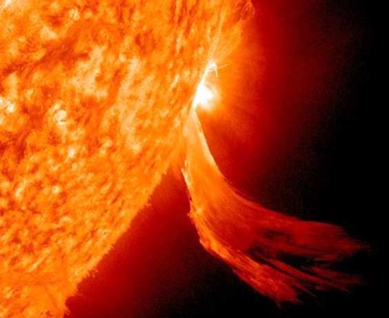
Fig. 3. Influence of supersaturation of the magnetic circuit of the
system. Vector B is a superposition of the internal mag-
power transformer on the occurrence of current overload the phe- netic field (it does not change with time) and the external
nomenon of semisaturation of the magnetic circuit of the power magnetic field (it changes ”slowly” with time, it is quasi-
transformer: (a) – without supersaturation, (b) – with supersatu- stationary). Only its vertical component Bz (t) is applied,
ration
ie the component perpendicular to the drawing in Fig. 2.
In the loop formed by the high-voltage line, which is con-
During magnetic storms, GICs reach high values and nected at its beginning and end to the high-voltage wind-
cause accidents of power transformers. From (1) it fol- ings of the power transformers is induced (according to
lows an important finding that the magnitude of GIC the law of induction) a voltage
depends on the derivation of the geomagnetic induction
vector B(t), ie on the rate of variation of the external dΦ dBz
geomagnetic field, not on its magnitude, as is often mis- V0 (t) = =S . (2)
dt dt
takenly stated.
The magnetic induction B(t) and thus also the GIC This equation holds under the assumption that intensity
have a random time course, and although there is talk of of the geomagnetic field Bz is equally distributed along
rapid variations in the external magnetic field, it changes the high-voltage line. In (2), the magnetic induction flux
relatively slowly, compared to alternating electrical quan- Φ is linked with a loop whose area is S = al , where l is
tities of industrial frequency. Magnetic storms are changes the length of the vhv line and a is the distance between
in units of nT/min. Depending on the time, GICs es- the conductors of the high voltage line.252 D. Mayer: PROTECTION OF POWER TRANSFORMERS AGAINST THE EFFECT OF MAGNETIC STORMS
windings of both transformers. The high-voltage line is
B
designed as a bundle conductors and is dimensioned in
such a way that there is no risk of thermal damage. It is
more complicated with transformers. Let us observe the
current i(t) in a high voltage line.
0
I1 I2 i1
• If there is no magnetic storm, GIC I0 = 0 and both
transformers operate in normal mode. The operating
point moves in the linear part of their magnetization
characteristic, ie below the knee of this curve. The
power system according to Fig. 2 is linear, all cur-
L rents and voltages in the circuit change harmoniously,
Fig. 3(a).
L1 • During a magnetic storm, a quasi-stationary voltage
V0 is induced in the high-voltage line and a quasi-
L2
stationary GIC I0 passes through the line. Let us ob-
0 i1 serve the current flowing through the vhv line. The op-
erating point on the magnetization curve of the trans-
Fig. 4. The course of inductance of the power transformer winding
during supersaturation of its magnetic circuit formers is shifted by the value I0 , the zero position of
the operating point is 0, Fig. 3(b). In the half-period,
when i(t) < I0 the operating point moves in the linear
The induced voltage V0 in the loop results in an in-
part of the magnetization curve (ie below the knee),
duced GIC I0 . The internal geomagnetic field is station-
ary, ie according to (2) it does not contribute to the mag- the system is linear and current overload of the trans-
nitude of the induced voltage V0 (ie not even to GIC I0 ). formers does not occur. However, in the half-period,
In contrast, the external geomagnetic field changes over when i(t) > I0 the operating point passes to the non-
time, but ”slowly” (compared to the current supplied by linear part of the magnetization curve (ie at and above
the generator i(t), whose frequency is 50 Hz), is quasi- the knee) and the current i(t) supersaturates the mag-
stationary. Only the resistances in this loop limit the mag- netic circuits of the transformers. The permeability of
nitude of the current I0 in the loop, formed by the vhv magnetic circuits (µ = B/H) has decreased and thus
line and the high-voltage windings of both transformers. the inductance of the transformer windings will also
Measurements on real power systems have shown that the decrease, the system is nonlinear, Fig. (4). Due to the
induced voltage V0 reaches in the order of up to hundreds quasi-stationary current I0 , the magnetizing current
of V during magnetic storms and the subsequent current
curve has changed its shape, its effective value is con-
I0 in the vhv line up to tens of A [11],[18].
siderably higher than when the geomagnetic field did
Geomagnetically induced current I0 is superimposed
not affect the system, ie when it was I0 = 0 , the high-
to the working current i(t) supplied by the source, the
voltage windings of both transformers become over-
current I0 + i(t) passes in the vhv line. Its rms value
is a measure of dissipated thermal energy. (According to heated. This phenomenon is called semisaturation of
Joule’s law, the dissipated electrical energy per thermal magnetic circuits. The theoretical solution [5,6] (and
energy is proportional to the square of the rms current the investigation of faults in practice [12] to [19] (show
value.) This energy thermally endangers the conductors that the current overload can range from 2.5 times to
of the high-voltage line, but above all the high-voltage three times the nominal value.
1 vhv 1
lv lv
i(t) + I 0
u(t)
2
2
3 3
=
V0
Fig. 5. A simple model of a single-phase electrical supply system, whose power transformers are protected by superconducting reactors:
1 – sensor-indicator of the quasi-stationar current I0 in the high voltage transmission line, 2 – a switch that connects/disconnects the
superconducting reactor to the high voltage winding of the power transformer, 3 – single-phase superconducting reactorJournal of ELECTRICAL ENGINEERING 72(2021), NO4 253
1 • If the coil of the frequency filter is made of a common
I0
(not superconducting) material, for example from cop-
per, Rf 6= 0 . The filter provides only partial protec-
tion. (For example, when Rf = Rt , then It = 0.5I0 .)
It For partial protection of the transformers, a frequency
If
filter can be implemented with a conventional iron re-
3 2 actor. The sharper the inequality Rf < Rt , the more
efficient the protection by the frequency filter, but the
Lf Lt
greater the weight and dimensions of the reactor. The
Rf Rt advantage of this method of transformer protection
is that it does not require cryotechnical equipment,
the disadvantage is only partial protection. As an ex-
ample, consider a frequency filter whose resistance is
Fig. 6. Distribution of the quasi-direct current I0 into the current Rf = Rt /4 , ie the cross-section of its coil is four times
If passing through the frequency filter 3 and into the current It in
the high-voltage winding of the transformer 2
larger than the cross-section of the high voltage wind-
ing of the transformer. Then, according to (3), a quasi-
stationary current in hv winding of the transformer is
5 A new way of protecting transformer It = 0.2I0 , ie only 20 percent of current I0 in the
windings from magnetic storms hv winding of the transformer in comparison with the
current in the unprotected winding. However, at the
A new method of protecting the transformer windings cost of the frequency filter having approximately four
consists in connecting a frequency filter in parallel with times the weight of the transformer’s hv winding.
the high-voltage winding of both transformers during a The connection/disconnection of the frequency filter
geomagnetic storm, Fig. 5. The frequency filter consists to the power system can be automated, Fig. 5. If a geo-
of a coil wound on a ferromagnetic core. It can be modeled magnetic storm Bz (t) acts on the power system, a quasi-
by series connection of resistance Rf and inductance Lf , stationary voltage V0 and then a current I0 is induced
Fig. 6. The current I0 induced in the vhv line is divided in the vhv line. Its magnitude is monitored by sensor
into the current If passing through the frequency filter
1. As soon as the current I0 reaches a preselected (ad-
and the current It in the high-voltage winding of the
justable) value, it activates both switches 2 at the be-
transformer
ginning and end of the transmission path and connects
Rt Rf frequency filters in parallel to the high-voltage windings
If = , It = , (3) of both transformers. The current I0 , in whole or in part
Rf + Rt Rf + Rt
(depending on the type of frequency filter), does not flow
All three currents are quasi-stationary, so limited only through the high-voltage windings of both transformers,
by resistances. but through frequency filters. As soon as the geomagnetic
storm stops, the current I0 drops and the sensor acti-
• A frequency filter with zero resistance (Rf → 0) will
vates both switches 2, which disconnect both frequency
provide perfect protection for the transformer. Accord-
ing to (3), all current I0 then flows through the fre- filters from the transformer windings. In addition to the
quency filter (If = I0 ) , while no GIC passes through quasi-stationary current I0 , an alternating current also
the windings of the transformers (It = 0). Such a fre- flows through the frequency filters, which has an induc-
quency filter can be realized by a coil (with a ferro- tive character and the impedance of the filter coil deter-
magnetic core), made of a high-temperature supercon- mines its magnitude. If this current increases the reactive
ductor, brought into a superconducting state. It is a power in the system and thus reduces the power factor
superconducting reactor, which includes a cryotechni- (cos ϕ) to undesirable values, it can be compensated in
cal device that produces liquid nitrogen, which cools the usual way, ie by connecting a compensator in parallel,
the frequency filter coil to a critical temperature at which is most often a static capacitor.
which the coil resistance is Rf → 0 . The advantage of Figure 7 shows a three-phase network with transformer
this frequency filter is perfect protection of the trans- protection by frequency filters at the point of connection
former winding, the disadvantage is the need cryotech- to the distribution network. The three-phase supercon-
nical equipment. ducting reactor in connection Y is here connected to the
Note that superconducting coils are usually used to high-voltage winding of a step-down power three-phase
generate extremely strong magnetic fields, using ex- transformer, connected between the high-voltage trans-
tremely high magnetizing currents. Thus, non-ferrous mission line and the distribution network. The trans-
(”air”) superconducting coils are used for strong mag- former winding is connected to the grounded Y-D node.
netic fields. In our case, however, the superconductor of Similarly, at the point of connection of the generator
the frequency filter coil only serves to reach Rf = 0 , so the to the step-up transformer, a superconducting reactor is
coil can have a magnetic circuit made of ferromagnetic connected in parallel to the high-voltage winding of the
material, which is of course advantageous. transformer.254 D. Mayer: PROTECTION OF POWER TRANSFORMERS AGAINST THE EFFECT OF MAGNETIC STORMS
1 2 6
3
4
5
Fig. 7. Connection of a three-phase superconducting reactor to the high-voltage side of a step-down power transformer in a YD
connection, converting electrical power into the distribution network: 1 – high voltage transmission line, 2 – three-phase step-down
power transformer in YD connection with zero output, 3 – indicator of quasi-stationar current I0 in high voltage transmission line, 4 –
switch to connect/disconnect superconducting reactor in the transmission system, 5 – three-phase superconducting reactor in connection
Y with output zero, 6 – three-phase distribution network simulated by three-phase impedance in connection Y with ground
The essence of the new method of protection of trans- rare occurrence of magnetic storms, its positive prop-
formers against the effects of magnetic storms was de- erties are used only sporadically and it is significantly
scribed here on an elementary model of the power sys- uneconomical in terms of investment and operation.
tem. However, frequency filters for complete or partial Works [20-23] describe a power electronic device that
protection of transformers can be used in cooperation limits a quasi-stationary GIC induced by a geomagnetic
with power transformers that are part of any topologi-
storm to a three-phase vhv line by conducting it to ground
cally complex system.
and thereby limiting its input to the hv winding of the
power transformer.
6 Older proposals on how to protect the
energy system from magnetic storms
7 Conclusion
The methods of protection of power transformers
against magnetic storms proposed so far are generally The collapse of the electricity system is a serious tech-
imperfect. For completeness, we will remind them here. nical event, which, especially in densely populated areas,
• Due to the predicted geomagnetic storm, a smaller can lead not only to huge economic losses, but also to
or larger part of the system is switched off, which threats to the safety of the population. One of the com-
leads to a controlled collapse of the system. After the mon causes of the collapse of the power system are rapid
storm subsides, the system is restored to its original anomalies of the geomagnetic field - magnetic storms. In-
state. The disadvantage of this method of protection is creasing industrialization means that disturbances caused
the breach of supplier-customer relations between the
by magnetic storms are not uncommon, especially in the
provider and the consumer and, as a rule, the resulting
Nordic countries, and have therefore recently received at-
need to compensate for economic losses caused by a
tention.
power outage.
• The phenomenon of semisaturation, which is the cause The presented work describes a new method of trans-
of thermal overload and subsequent damage to trans- former protection, which uses frequency filters. Two types
formers, develops only to a lesser extent in power of frequency filters are described: filters with supercon-
transformers whose magnetic circuit is strongly over- ductor coils for complete protection, and filters with coils
sized. In such robust transformers, the working area of common materials for partial protection. It is char-
of the transformer lies in the linear part of its magne- acterized by reliable exclusion, resp. limiting the occur-
tization characteristic during DC pre-magnetization. rence of current overload of transformers, low purchase
The disadvantage is that the oversized, robust trans- price, the possibility of easy adaptation to existing elec-
former is magnetically unused in normal operation. trical systems and then automatic, unattended operation.
The robust transformer has more weight and dimen- The device is relatively simple and robust, which virtually
sions, more losses in iron and more noise. Due to the eliminates its failure rate.Journal of ELECTRICAL ENGINEERING 72(2021), NO4 255
References [16] M. Stork and D. Mayer, “Direct currents in power transformers”,
Journal of Electrical Engineering, vol. 70 (2019), no. 1, pp. 68-72.
[1] E. N. Parker, Cosmical magnetic fields, Oxford, Clarendon [17] J. Ramírez-Niño “Core saturation effect of geomagnetic induced
Press, 1979. currents in power transforms”, Journal of Applied Research and
[2] E. Priest, Solar magnetohydrodynamics, Dordecht, D. Reidel Technology, 14 (2016), pp. 87-92.
Publ. Co., 1984.
[18] R. Price, “Geomagnetically induced currents effects on trans-
[3] R. E. Benestand, Solar aktivity and Earths climate, Berlin, formers”, IEEE Transactions on Power Delivery, vol. 17, no. 4,
Springer-Verlag, 2003. October 2003, pp. 1002-1008.
[4] http://www.asu.cas.cz/cz/veda-a-vyzkum/vedecka-oddeleni/
[19] L. Bolduc, et al , “Development of a DC current-blocking dvice
slunecni-oddeleni, (In Czech).
for transformer neutrals”, IEEE Trans. on Power Delivery, 2995,
[5] D. Mayer, “Geomagnetic storms and their effect on the electrical Jan., vol. 20, no. 1, pp. 163-168.
system.”, ELEKTRO, no. 8-9, 2016, pp. 58-62,(In Czech).
[20] V. Gurevich, “Protection of power transformers against geomag-
[6] D. Mayer and Ulrych B. “Influence of magnetic storm on power
netically induced currents”, Serbian Journal of Electrical Engi-
system transformers.”, ELEKTRO, no. 3, 2018, pp. 2-4, (In
neering, vol. 8, no. 2, November 2011, pp. 333-339.
Czech).
[7] D. Mayer, “Contribution to investigation of influence of geo- [21] V. I. Gurevich, “Stability of microprocessor relay protection and
magnetic stroms on electrification system.”, Acta Technica, 58 automation systems against intentional descructive electromag-
(2013), pp. 351-365. ntic impacts, Part I”, Components and Technologies, no. 4, 2011,
[8] D. Mayer, “The effect of geomagnetic storms on the electrifi- pp. 116-122. Part II, dtto, no. 5, 2011, pp. 129-136 (in Russian).
cation system”, Cyclonic and Geomagnetic Storms, Predicting [22] V. I. Gurevich, Protection devices and systems for high-voltage
factors, formation and enviromental impacts, Editor, Victoria P. applications, Marcel Dekker, New York, USA, 2003.
Banks, Nova Science Publishers, Inc., New York 2015, pp. 1-18. [23] H. Zhu and T. J. Overbyte, “Blocking device placement for mit-
ISBN 978-1-63482-360-9. igating of geomagnetically induced currents”, IWWWE Trans.
[9] https://www.ig.cas.cz/vyzkum-a-vyuka/oddeleni/geomagnetika on Power Systems, 2015, July, vol. 30, no. 4.
/predpoved-geomagnetick-aktivity/, (in Czech). [24] A. Rezaei-Zare, et al , “Analysis of three-phase transformer re-
[10] L. J. Lanzerotti, “”, Space weather effects on technologies, Space sponse due to GIC using an advanced duality-based model”,
weather effects on technologies, In, Song P. et al (eds.), Space Browse Journals and Magazines, IEEE Transactions on Power
Wheater. American Geophysical Union, Geophys. Monograph., Delivery, vol. 31, no. 5, view document 273.
2001, 125, pp. 11-25.
[11] R. Nishiura, S. Yamashita, and S. Kano, “Simulation analysis Received 5 August 20221
of geomagnetically-induced currents (GIC) effects on shell-form
transformers.”, Power and Energy Society General Meeting,
(PES), 2013 IEEE, 21. - 25. July 2013. Daniel Mayer (Prof, Ing, DrSc) received the Ing, PhD
[12] R. Girgis,“Effects of geomagnetically induced currents on power and DrSc degrees in electrical engineering from Technical Uni-
transformers and power systems”, CIGRE, 21, rue d’ Artois, versity in Prague, Czech Republic. In 1959 Associate Profes-
F-75008 Paris, A2-304, pp. 1-8. sor at the University of West Bohemia in Pilsen, in 1968 full
[13] K. J. Patel, “An alalytic review of geomagnetically induced Professor of the Theory of Electrical Engineering. Many years
current effects in power system”, Internat. Conf. On Electri-
he was head of the Department of Theory of Electrical En-
cal, Electronics and Optimization Techniques, (ICEEOT), 3-5
March 2016. gineering. Research interests: circuit theory, electromagnetic
[14] J. R. Niño, “Core saturation effect of geomagnetic induced cur- field theory, electrical machines and apparatus, history of elec-
rents in power transformers”, Journal of Applied Research and trical engineering. He published 9 books, more than 350 sci-
Technology, 14 (2016), pp. 87-92, 2011. entific papers and 14 patents. He is a member of editorial
[15] F. Bachinger et al , “Direct current in transformers, effects and boards of several international journals and leader of many
compensation.”, CIGRE, //www.cigre.org). grant projects.You can also read