9 x 2 4K Presentation Matrix Switch VP1920 User Manual - www.aten.com
←
→
Page content transcription
If your browser does not render page correctly, please read the page content below
9 x 2 4K Presentation Matrix Switch
       VP1920 User Manual

           www.aten.com
VP1920 User Manual EMC Information FEDERAL COMMUNICATIONS COMMISSION INTERFERENCE STATEMENT: This equipment has been tested and found to comply with the limits for a Class A digital device, pursuant to Part 15 of the FCC Rules. These limits are designed to provide reasonable protection against harmful interference when the equipment is operated in a commercial environment. This equipment generates, uses, and can radiate radio frequency energy and, if not installed and used in accordance with the instruction manual, may cause harmful interference to radio communications. Operation of this equipment in a residential area is likely to cause harmful interference in which case the user will be required to correct the interference at his own expense. FCC Caution: Any changes or modifications not expressly approved by the party responsible for compliance could void the user's authority to operate this equipment. CE Warning: Operation of this equipment in a residential environment could cause radio interference. This device complies with Part 15 of the FCC Rules. Operation is subject to the following two conditions: (1) this device may not cause harmful interference, and (2) this device must accept any interference received, including interference that may cause undesired operation. RoHS This product is RoHS compliant. ii
VP1920 User Manual

User Information

Online Registration
Be sure to register your product at our online support center:

International         http://eservice.aten.com

Telephone Support
For telephone support, call this number:

International         886-2-8692-6959
China                 86-400-810-0-810
Japan                 81-3-5615-5811
Korea                 82-2-467-6789
North America         1-888-999-ATEN ext 4988
                      1-949-428-1111

User Notice
All information, documentation, and specifications contained in this manual are
subject to change without prior notification by the manufacturer. The
manufacturer makes no representations or warranties, either expressed or
implied, with respect to the contents hereof and specifically disclaims any
warranties as to merchantability or fitness for any particular purpose. Any of the
manufacturer's software described in this manual is sold or licensed as is.
Should the programs prove defective following their purchase, the buyer (and
not the manufacturer, its distributor, or its dealer), assumes the entire cost of all
necessary servicing, repair and any incidental or consequential damages
resulting from any defect in the software.

The manufacturer of this system is not responsible for any radio and/or TV
interference caused by unauthorized modifications to this device. It is the
responsibility of the user to correct such interference.

The manufacturer is not responsible for any damage incurred in the operation
of this system if the correct operational voltage setting was not selected prior to
operation. PLEASE VERIFY THAT THE VOLTAGE SETTING IS CORRECT
BEFORE USE.

                                                                                    iii
VP1920 User Manual
Package Contents
1 VP1920 9 x 2 4K Presentation Matrix Switch
1 Power Cord
1 IR Receiver
1 IR Remote Control
1 User Instructions
Note: Make sure that all of the items are present and in good order. If anything
is missing or was damaged in shipping, please contact your dealer for
further assistance.
ivVP1920 User Manual
Table of Contents
EMC Information. . . . . . . . . . . . . . . . . . . . . . . . . . . . . . . . . . . . . . . . . . . . . ii
RoHS . . . . . . . . . . . . . . . . . . . . . . . . . . . . . . . . . . . . . . . . . . . . . . . . . . . . . ii
User Information . . . . . . . . . . . . . . . . . . . . . . . . . . . . . . . . . . . . . . . . . . . . iii
Package Contents . . . . . . . . . . . . . . . . . . . . . . . . . . . . . . . . . . . . . . . . . . .iv
About this Manual . . . . . . . . . . . . . . . . . . . . . . . . . . . . . . . . . . . . . . . . . . vii
Conventions . . . . . . . . . . . . . . . . . . . . . . . . . . . . . . . . . . . . . . . . . . . . . . . viii
Product Information . . . . . . . . . . . . . . . . . . . . . . . . . . . . . . . . . . . . . . . . . viii
1. Introduction
Overview. . . . . . . . . . . . . . . . . . . . . . . . . . . . . . . . . . . . . . . . . . . . . . . . . . . 1
Benefits . . . . . . . . . . . . . . . . . . . . . . . . . . . . . . . . . . . . . . . . . . . . . . . . . . . 2
Features . . . . . . . . . . . . . . . . . . . . . . . . . . . . . . . . . . . . . . . . . . . . . . . . . . . 3
Planning the Installation . . . . . . . . . . . . . . . . . . . . . . . . . . . . . . . . . . . . . . . 5
Required Equipment . . . . . . . . . . . . . . . . . . . . . . . . . . . . . . . . . . . . . . . 5
Optional Equipment. . . . . . . . . . . . . . . . . . . . . . . . . . . . . . . . . . . . . . . . 5
2. Hardware Setup
Components . . . . . . . . . . . . . . . . . . . . . . . . . . . . . . . . . . . . . . . . . . . . . . . . 7
VP1920 Front View . . . . . . . . . . . . . . . . . . . . . . . . . . . . . . . . . . . . . . . . 7
VP1920 Rear View . . . . . . . . . . . . . . . . . . . . . . . . . . . . . . . . . . . . . . . . 9
IR Remote Control . . . . . . . . . . . . . . . . . . . . . . . . . . . . . . . . . . . . . . . 11
LED Indicators . . . . . . . . . . . . . . . . . . . . . . . . . . . . . . . . . . . . . . . . . . 13
Rack Mounting . . . . . . . . . . . . . . . . . . . . . . . . . . . . . . . . . . . . . . . . . . . . . 14
Installation . . . . . . . . . . . . . . . . . . . . . . . . . . . . . . . . . . . . . . . . . . . . . . . . 15
3. Operation
Overview. . . . . . . . . . . . . . . . . . . . . . . . . . . . . . . . . . . . . . . . . . . . . . . . . . 17
Operation Considerations . . . . . . . . . . . . . . . . . . . . . . . . . . . . . . . . . . 17
Switching the Display Source . . . . . . . . . . . . . . . . . . . . . . . . . . . . . . . . . . 17
Auto Switching . . . . . . . . . . . . . . . . . . . . . . . . . . . . . . . . . . . . . . . . . . 17
Manual Switching . . . . . . . . . . . . . . . . . . . . . . . . . . . . . . . . . . . . . . . . 17
Changing the Source for Mirror Mode. . . . . . . . . . . . . . . . . . . . . . . . . 18
Display Modes . . . . . . . . . . . . . . . . . . . . . . . . . . . . . . . . . . . . . . . . . . . . . 19
Understanding Display Modes . . . . . . . . . . . . . . . . . . . . . . . . . . . . . . 19
Setting the Display Mode . . . . . . . . . . . . . . . . . . . . . . . . . . . . . . . . . . 19
Operating PCs/Laptops/Tablets . . . . . . . . . . . . . . . . . . . . . . . . . . . . . . . . 20
Hardware Setup . . . . . . . . . . . . . . . . . . . . . . . . . . . . . . . . . . . . . . . . . 20
Operation . . . . . . . . . . . . . . . . . . . . . . . . . . . . . . . . . . . . . . . . . . . . . . 20
Locking the Panel Pushbuttons . . . . . . . . . . . . . . . . . . . . . . . . . . . . . . . . 21
Manual Lock . . . . . . . . . . . . . . . . . . . . . . . . . . . . . . . . . . . . . . . . . . . . 21
Automatic Lock . . . . . . . . . . . . . . . . . . . . . . . . . . . . . . . . . . . . . . . . . . 21
Firmware Upgrades . . . . . . . . . . . . . . . . . . . . . . . . . . . . . . . . . . . . . . . . . 22
System Settings . . . . . . . . . . . . . . . . . . . . . . . . . . . . . . . . . . . . . . . . . . . . 23
vVP1920 User Manual
4. RS-232 Serial Commands
Overview . . . . . . . . . . . . . . . . . . . . . . . . . . . . . . . . . . . . . . . . . . . . . . . . . . 27
Setup. . . . . . . . . . . . . . . . . . . . . . . . . . . . . . . . . . . . . . . . . . . . . . . . . . . . . 27
Command Guidelines . . . . . . . . . . . . . . . . . . . . . . . . . . . . . . . . . . . . . . . . 28
Commands . . . . . . . . . . . . . . . . . . . . . . . . . . . . . . . . . . . . . . . . . . . . . . . . 29
System Firmware Version Command . . . . . . . . . . . . . . . . . . . . . . . . . 29
Read Command . . . . . . . . . . . . . . . . . . . . . . . . . . . . . . . . . . . . . . . . . 29
Source Switching Command . . . . . . . . . . . . . . . . . . . . . . . . . . . . . . . . 29
Auto Switching Command . . . . . . . . . . . . . . . . . . . . . . . . . . . . . . . . . . 30
Enabling/Disabling Display Command . . . . . . . . . . . . . . . . . . . . . . . . 31
Display Mode Command . . . . . . . . . . . . . . . . . . . . . . . . . . . . . . . . . . . 31
EDID Mode Command . . . . . . . . . . . . . . . . . . . . . . . . . . . . . . . . . . . . 32
HDCP Authentication Command . . . . . . . . . . . . . . . . . . . . . . . . . . . . . 32
CEC Status Command . . . . . . . . . . . . . . . . . . . . . . . . . . . . . . . . . . . . 32
Mute Command . . . . . . . . . . . . . . . . . . . . . . . . . . . . . . . . . . . . . . . . . 33
Baud Rate Command . . . . . . . . . . . . . . . . . . . . . . . . . . . . . . . . . . . . . 33
Standby Mode Command . . . . . . . . . . . . . . . . . . . . . . . . . . . . . . . . . . 33
Restoring Default Command . . . . . . . . . . . . . . . . . . . . . . . . . . . . . . . . 33
Firmware Upgrade Command . . . . . . . . . . . . . . . . . . . . . . . . . . . . . . . 33
Appendix
Safety Instructions. . . . . . . . . . . . . . . . . . . . . . . . . . . . . . . . . . . . . . . . . . . 35
General . . . . . . . . . . . . . . . . . . . . . . . . . . . . . . . . . . . . . . . . . . . . . . . . 35
Rack Mounting . . . . . . . . . . . . . . . . . . . . . . . . . . . . . . . . . . . . . . . . . . 37
Technical Support . . . . . . . . . . . . . . . . . . . . . . . . . . . . . . . . . . . . . . . . . . 38
Specifications . . . . . . . . . . . . . . . . . . . . . . . . . . . . . . . . . . . . . . . . . . . . . . 39
Limited Warranty . . . . . . . . . . . . . . . . . . . . . . . . . . . . . . . . . . . . . . . . . . . 41
viVP1920 User Manual
About this Manual
This user manual is provided to help you get the most from the VP1920 unit. It
covers all aspects of installation, configuration, and operation. An overview of
the information found in the manual is provided below.
Chapter 1, Introduction introduces you to the VP1920. Its purpose, features,
and installation considerations are described.
Chapter 2, Hardware Setup describes the hardware components of the
VP1920 and the supplied IR remote control, and details the steps that are
necessary to quickly and safely set up the VP1920.
Chapter 3, Operation provides details on panel operations and system settings.
Appendix provides a list of safety instructions and precautions, contact
information for ATEN technical support, product specifications, and other
technical information.
Note:
Read this manual thoroughly and follow the installation and operation
procedures carefully to prevent any damage to the unit or any connected
devices.
ATEN regularly updates its product documentation for new features and
fixes. For an up-to-date VP1920 documentation, visit
http://www.aten.com/global/en/
viiVP1920 User Manual
Conventions
This manual uses the following conventions:
Monospaced Indicates text that you should key in.
[] Indicates keys you should press. For example, [Enter] means to
press the Enter key. If keys need to be chorded, they appear
together in the same bracket with a plus sign between them:
[Ctrl+Alt].
1. Numbered lists represent procedures with sequential steps.
♦ Bullet lists provide information, but do not involve sequential steps.
→ Indicates selecting the option (on a menu or dialog box, for
example), that comes next. For example, Start → Run means to
open the Start menu, and then select Run.
Indicates critical information.
Product Information
For information about all ATEN products and how they can help you connect
without limits, visit ATEN on the Web or contact an ATEN Authorized Reseller.
Visit ATEN on the Web for a list of locations and telephone numbers:
International http://www.aten.com
North America http://www.aten-usa.com
viiiChapter 1
Introduction
Overview
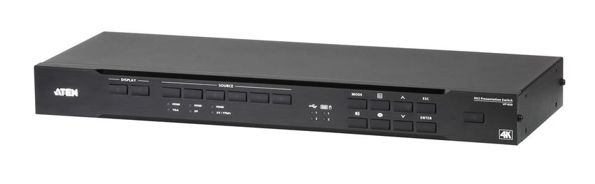
The ATEN VP1920 is a 3-in-1 presentation switch integrating a video matrix
switching, audio processing, and analog-to-digital conversion. With nine inputs
to two 4K outputs, it is designed to boost the efficiency and impact of
professional presentations.
With streamlined control from front-panel pushbuttons, IR remote controller,
OSD, and RS-232, the VP1920 reduces not only system device count, but also
lowers operation complexity. It is suitable for all small-to-medium sized
corporate and education presentation environments, such as meeting rooms,
classrooms, training rooms, or any other presentation setting, such as in
exhibition centers or hotels.
1Chapter 1. Introduction Benefits Fast Multi-format Audio-video Switching The VP1920 allows for fast switching among 6 HDMI and 3 combo inputs (HDMI/VGA, HDMI/DisplayPort, HDMI/Component/Composite) to 2 HDMI outputs and supports Coaxial, Toslink, Stereo audio outputs. USB Control Routing for PCs and Touch Panels The VP1920 integrates PC and touch panel controls with other devices into one system with its USB ports. This allows for independent switching of USB peripheral ports and keyboard/mouse control to a designated computer source. Selectable Matrix, Mirror, and PIP* Modes Three different display modes meet the needs of various events or presentation styles. Note: The PIP mode supports resolutions up to 1080p. Source Preview The previous function allows you to quickly identify and switch to your target content. No more guessing which port connects to which content source. 2
VP1920 User Manual
Features
Multi-format AV Switching with Simplicity
Supports 9 multi-format inputs and 2 HDMI outputs:
3 combo inputs (HDMI/VGA, HDMI/DisplayPort, HDMI/AV/YPbPr)
3 HDMI inputs
2 HDMI outputs
VGA port supports universal analog input formats (RGBHV/RGBs/YCbCr/
YPbPr)
Embed/de-embed audio-HDMI/DisplayPort audio signals can be extracted
to digital/analog audio signals; stereo/composite/component audio can be
embedded to digital audio signals
High-definition Video with Optimum Output
Superior video quality up to 4K @ 60 Hz (4:2:0) or 4K @ 30 Hz
(4:4:4)(HDMI/DP)
EDID ExpertTM – automatically selects the optimum EDID settings for
smooth power-up, high-quality display and the best video resolution across
connected devices
HDMI (3D, Deep Color, 4K); HDCP 1.4 compliant
Versatile, Streamlined Operation
Multiple control via front-panel pushbuttons, RS-232, OSD, and IR remote
control
Source preview – quickly identify and switch to the target content
Selectable display modes (Matrix, Mirror, or PiP) for fast switching among
sources
Auto switching – automatically switches to a new source as soon as it is
detected
Supports stand-by mode for power saving and fast waking up
3Chapter 1. Introduction
Extended Flexibility for USB Peripherals
USB ports enable keyboard/mouse or touch panel control over the
connected computers
Control focus for keyboard/mouse and USB peripherals can be individually
switched to a designated computer source
4VP1920 User Manual
Planning the Installation
Required Equipment
Prepare the following before installing the VP1920 unit:
Source devices
This can be PCs and/or HDMI source devices such as blue-ray player,
VCR Player, or TV Box etc.
Appropriate cables that connect your source devices to the VP1920
Display devices
HDMI cables that connect your display devices to the VP1920
Optional Equipment
Optionally prepare the following:
USB drives to serve as external storage
A set of keyboard and mouse for accessing computers connected as
Source 1 and 2
A software or hardware controller to configure the settings of the VP1920
using RS-232 interface
For information on the number of equipped ports for each connection interface,
see Specifications, page 39.
5Chapter 1. Introduction
This Page Intentionally Left Blank
6Chapter 2
Hardware Setup
1. Please review the safety information regarding the placement of this
device in Safety Instructions, page 35.
2. Do not power on the VP1920 until all the necessary hardware is
connected.
Components
VP1920 Front View
1 2 3 64 5
No. Component Description
1 Display Selection Press a display pushbutton to focus a display.
Pushbuttons
2 Source Selection Press a source pushbutton to designate a source
Pushbuttons for a focused display.
7Chapter 2. Hardware Setup
No. Component Description
3 Function
: Opens the OSD of display mode
Pushbuttons
settings. For more details about display modes,
see Setting the Display Mode, page 19.
:
Opens the OSD of system settings for the
VP1920. For more details about system
settings, see System Settings, page 23.
Press the pushbutton twice to close the
OSD.
: Opens the OSD for setting the source of
local audio output.
: Activates a preview of the current display
mode. For more details, see Changing the
Source for Mirror Mode, page 18.
4 Navigation
:
Pushbuttons
Navigate up and down the OSD.
Press to lock or unlock the panel
pushbuttons. You can also set the VP1920
to automatically lock the panel pushbuttons.
For more information, see Locking the
Panel Pushbuttons, page 21.
: Goes to the next level of settings in
the OSD or selects a setting.
: Returns to the previous level of the
OSD.
5 Standby Press the pushbutton to enable the standby mode.
Pushbutton Press again to wake the unit.
8VP1920 User Manual
VP1920 Rear View
11 12 1 2 3 5 6 8a 9
13 4 7 8b 10
No. Component Description
1 Source 1 A combo port that can receive up to two source
devices (one VGA In with a Stereo Audio In and
one HDMI In).
2 Source 2 A combo port that can receive up to two source
devices (one DisplayPort In and one HDMI In).
3 Source 3 A combo port that can receive up to two sources
(one A/V In or Comp In and one HDMI In).
4 Source 4, 5, 6 Receive HDMI sources.
5 Stereo Audio Out Connects to a speaker.
6 Digital Audio Out Connects to a speaker via the Optical Audio Out or
Coaxial Audio Out port.
7 HDMI Out Ports Connect to HDMI-enabled displays.
8a USB Type-A (1.1) Connect to a keyboard and a mouse.
Ports
8b USB Type-A Ports Connect to USB drives as external storages.
9 IR Receiver Port Connects to an IR receiver to receive IR signals
from the IR remote control.
10 RS-232 Serial Port Connects to a hardware or software controller to
transmit serial data.
11 Power Socket Receives a power cord to supply power to the
VP1920.
12 Power Switch Enables (ON) or disables (OFF) the power supply
to the VP1920.
9Chapter 2. Hardware Setup
No. Component Description
13 Grounding Grounds the VP1920 to prevent damages to the
Terminal VP1920 from power surge or static electricity.
Note: Source 1, 2, and 3 of the unit can each receive more than one input, but
can only output one source at a time.
10VP1920 User Manual
IR Remote Control
11
4 22
5 33
No. Buttons Description
1 On/Off Button Turns the VP1920 on or off.
2 Source Buttons Press a Source button to assign the source to a
focused display.
3 Navigation Buttons
: Press these buttons to navigate up
and down the OSD.
: Press this button to return to the previous
level of options of the OSD.
: Press this button to go to the next level of
options or to select an option.
4 Display Buttons Press a display button to focus the display.
11Chapter 2. Hardware Setup
No. Buttons Description
5 Function Buttons
Mode :
Opens the display mode settings. For more
details about display modes, see Setting
the Display Mode, page 19.
When the display mode menu is open,
press this button to cycle through the
options.
Menu :
Opens the OSD of system settings for the
VP1920. For more details about system
settings, see Setting the Display Mode,
page 19.
Press the button twice to close the OSD.
Audio : Opens the OSD for setting the
source of local audio output.
Preview : Activates a preview of the
current display mode. For more details, see
Changing the Source for Mirror Mode, page 18.
12VP1920 User Manual
LED Indicators
You can find the LEDs of the VP1920 on the top panel as illustrated below. See
the table below for details about LED indication.
1 2 64 6
3 64 65
No. LED Indication System Status
1 Display Pushbuttons Light amber The display device (Display A or B) is
focused.
2 Source Pushbuttons Light green The source is selected for display.
3 Source LEDs Light green The indicated source is selected as the
output for the combo port.
4 USB LEDs Light amber The attached USB drives are accessible by
the indicated source device (Source 1 or
2).
5 Keyboard and Light amber The control of the attached keyboard and
Mouse LEDs mouse is switched to the indicated source
(Source 1 or 2).
6 Power Pushbutton Lights green The VP1920 is powered on.
Lights orange The VP1920 is in standby mode.
13Chapter 2. Hardware Setup Rack Mounting The VP1920 can be mounted in a 19” (1U) system rack. To conveniently access the front-panel pushbuttons for configuration and operation, mount the unit at the front of the rack so that the front panel faces outward. 1. Use the M3 x 6 Phillips hex head screws supplied with the Mounting Kit to screw the rack mounting brackets onto the front of the unit. 2. Position the unit in the front of the rack and align the holes in the mounting brackets with the holes in the rack. 3. Screw the mounting brackets to the rack. 14
VP1920 User Manual

Installation

Follow the steps below to safely install the VP1920 to sources, display devices,
and other equipment as required.

                                                                   5    8
                                              4
 9

              1                       2
                                                                            7
                                                                   6

                                                             3

1. Ground the unit with a grounding wire. Connecting one end of the
   grounding wire to the grounding terminal, and the other end to a suitable
   grounded object.

     Note: Do not omit this step. Proper grounding helps prevent damage to the
           unit from surges or static electricity.

2. Connect the unit to source devices.

     Note: You can connect sources of different interfaces to each of Source 1,
           2, and 3 and select one from each set when needed. For details on
           how to switch sources for each of these combo ports, see Switching
           the Display Source, page 17.

                                                                                15
Chapter 2. Hardware Setup
3. Use HDMI cables to connect HDMI displays to the HDMI Out ports.
Note: If you are only using one display, make sure to connect it to Display
A where the OSD menu displays.
4. Connect your audio devices to the Stereo Audio Out or Digital Audio Out
ports.
Note: By default, the connected speakers output the audio of the source
that is switched to on Display A.
5. Connect a keyboard and a mouse to the USB Type-A ports to access
computers connected as Source 1 or Source 2.
6. Connect USB peripherals to the USB Type-A ports to be controlled by
computers connected as Source 1 or Source 2.
7. To configure the unit’s settings via RS-232 commands, connect the unit to a
hardware or software controller. For details about RS-232 commands, see
Chapter 4, RS-232 Serial Commands.
8. To operate the unit using IR remote control, connect the supplied IR
Receiver to the IR Receiver port.
9. Plug the Power Cord to the Power Socket and put the Power Switch to ON.
10. Power on any connected devices.
16Chapter 3
Operation
Overview
This chapter provides detailed information on the features of the VP1920’s on-
screen display (OSD), and how to locally operate the unit using the front-panel
pushbuttons and the IR remote control.
Operation Considerations
Make sure to use the IR remote control within the effective range (6 m), and
that there is a clear line-of-sight between the remote control unit and the IR
receiver connected to the VP1920.
The IR remote control and the VP1920’s front panel offer the same
operation capability. Use either method as required.
Switching the Display Source
Auto Switching
By default, VP1920 automatically switches to a new source on Display A as
soon as the source is detected. To disable automatic switching, press the Menu
button/pushbutton, and then go to Source > Auto Switch to disable the setting.
Manual Switching
You can manually switch the display source using the IR remote control and
the front-panel pushbuttons.
1. Skip this step if your displays are set to the mirror mode.
Press a Display button/pushbutton to focus a display. The pushbutton for
the selected display lights amber.
Note: If your displays are set to the PiP mode, press the Display A
pushbutton to focus the main display, and press the Display B
pushbutton to focus the inset window.
17Chapter 3. Operation
2. Press a Source button/pushbutton to assign the source to the focused
display. The pushbutton for the selected source lights green.
Note: For combo ports (Source 1, 2, and 3), the latest connected input will
be automatically selected as the output source for the set. To
manually change the source of a combo port, press the Source
button/pushbutton twice. The selected source LED lights green. To
change this priority, configure the Source settings in the OSD. For
details, see System Settings, page 23.
Changing the Source for Mirror Mode
When your displays are set to Mirror Mode, you can select your source from a
list of mini preview windows. To select or change the source for your displays
under mirror mode, follow the steps below.
1. Press the Preview button/pushbutton. The available sources appear in
mini preview windows.
2. Press the Up and Down button/pushbutton to focus a desired option. The
focused source moves out of the list.
3. Press the Enter button/pushbutton to select the source. The source is
immediately assigned.
18VP1920 User Manual
Display Modes
Understanding Display Modes
When you have two display devices connected to the VP1920, you can choose
among the following display modes:
Matrix Mode: This is the default setting. Select this mode to assign
different sources on the connected display devices.
Mirror Mode: Select this mode to generate a mirror view with which the
source on Display A is automatically assigned to Display B.
Picture-in-picture Mode (PiP): Select this mode to produce a composite
display with which the source on Display B is inserted into Display A in a
mini window.
Setting the Display Mode
By default, the VP1920 is set to the matrix mode with which you can assign
different sources to the connected displays. To change the display mode,
following the steps below:
Note: To change to the PiP mode, make sure to first assign the main source
(displayed in full) to Display A, and the subordinate source (displayed as
an inset window) to Display B before proceeding to the steps below.
1. Press the Mode button/pushbutton. The mode settings appear on
Display A.
2. Press the Mode button/pushbutton to cycle through the options.
3. Press the Enter button/pushbutton to select an option. The selected mode
is applied immediately.
19Chapter 3. Operation Operating PCs/Laptops/Tablets You can control connected PCs, laptops, and/or tablets using a keyboard and a mouse attached to your VP1920. Hardware Setup Follow the steps below to correctly install your PCs and/or laptops. 1. Connect your PC or laptop to Source 1 or Source 2 of the VP1920 depending on the equipped interface (VGA, DisplayPort, or HDMI). 2. Use a USB cable to connect your device to the USB host port of the Source group on the VP1920 that you use in step 1. 3. Connect a keyboard and a mouse to the back panel of the VP1920. Make sure to connect the keyboard and mouse to their indicated USB port. Operation By default, the VP1920 is set to automatically switch the control to the source that Display A shows. For example, if you have a laptop connected to Source 1, and the source is displayed on Display A, you can then control the laptop using the keyboard and mouse connected to the VP1920. In this case, the Keyboard/ Mouse and peripherals LEDs for “1” light amber to indicate that the keyboard/ mouse control is switched to Source 1, and that the Source 1 device (your laptop) can now access any USB devices attached to the VP1920. To protect confidential data from leaking, you can limit the access of USB peripherals to a particular source, and that the access will only be allowed when Display A is assigned with that particular source. Press the Menu button/ pushbutton, navigate to USB > Peripherals and select Source 1 or Source 2. 20
VP1920 User Manual

Locking the Panel Pushbuttons

You can have your panel pushbuttons locked to avoid accidentally changing
your configuration.

Manual Lock
Press and hold the       pushbutton until the Lock      icon on the pushbutton
lights red. To unlock, press and hold the     pushbutton until the Lock
icon dims.

Automatic Lock
To automatically lock the panel pushbuttons, follow the steps below.
1. Press the Menu button/pushbutton. The System Settings menu appears.
2. Navigate to General Settings > Panel Auto Lock. Select an idle duration
   upon which the panel pushbuttons are locked. When the pushbuttons are
   locked, the Lock       icon on the       pushbutton lights red.

                                                                            21
Chapter 3. Operation
Firmware Upgrades
Follow the steps below to upgrade the system firmware via the RS-232
command.
1. Make sure you have connected a PC to the VP1920 and configured the
required software. For details, see Setup, page 27.
2. Visit the product web page and download the following:
thefirmware file as required
the Firmware Upgrade Utility program
3. Save the downloaded files to the PC.
4. Use one of the following methods to enable the firmware upgrade mode:
In VP1920’s OSD, go to Maintenance > Firmware Upgrades, and
set the setting to Enable.
Execute the RS-232 command for upgrade.
5. From the PC, execute Firmware Upgrade Utility and follow on-screen
instructions to start the upgrade.
22VP1920 User Manual
System Settings
To access the system settings, follow the steps below.
1. Press the Menu button/pushbutton. The System Settings menu appears on
Display A.
2. Navigate to the setting you wish to configure.
3. Press the Enter button/pushbutton to select an option. The selected option
appears in square brackets for the setting.
Refer to the table below for an overview of the VP1920’s settings.
System Settings
Description
Note: Default settings are indicated in bold.
General Info OSD Enable Displays the current source, audio,
Settings Disable I/O, and display mode settings for
Display A and B.
RS-232 Baud 9600 Sets the baud rate for RS-232
Rate 19200 communications.
38400
115200
Panel Auto Lock 5s later Sets the VP1920 to automatically
30s later lock the panel pushbuttons when
they have been idled for the
5 mins later
selected duration.
Disable
USB KB/Mouse Auto Sets the source that can be
controlled by the VP1920’s
Source 1
console keyboard and mouse.
Source 2 Note: The source must also be
assigned to Display A for this
function to work.
Select Auto to allow Source 1 or
Source 2 to be controlled by the
VP1920’s console keyboard and
mouse, depending on which
source is assigned to Display A.
23Chapter 3. Operation
System Settings
Description
Note: Default settings are indicated in bold.
USB Peripheral Auto Sets the source that has access to
the VP1920’s USB peripherals.
Source 1
Note that the selected source must
Source 2 also be assigned to Display A for
this function to work.
Select Auto to allow either Source
1 or 2 to access the attached
peripherals, depending on which
one is assigned to Display A.
Note: The source device must be a
laptop, PC, or tablet, and is
connected to the USB host port on
the VP1920. For details on the
required setup, see Operating
PCs/Laptops/Tablets, page 20.
Audio Source Display A Sets the audio source for the
VP1920.
Display B
I/O All Sets the allowed output type
(stereo, digital, or both).
S/PDIF /
Coaxial
L/R
Mute Enable Mute or unmute the VP1920.
Disable
Source Auto Switch ON Enable this function to have
OFF Display A automatically switch to a
newly connected source.
Source 1 Auto Sets the input source for Source 1.
HDMI Auto: Source 1 automatically
switches to a newly detected
VGA
source.
HDMI or VGA: Source 1
defaults to the HDMI or VGA
source.
24VP1920 User Manual
System Settings
Description
Note: Default settings are indicated in bold.
Source Source 2 Auto Sets the input source for Source 2.
HDMI Auto: Source 2 automatically
switches to a newly detected
DisplayPort
source.
HDMI or DisplayPort: Source
2 defaults to the HDMI or
DisplayPort source.
Source 3 Auto Sets the input source for Source 3.
HDMI Auto: Source 3 automatically
switches to a newly detected
AV / YPbPr
source.
HDMI or AV/YPbPr: Source 3
defaults to the HDMI or AV/
YPbPr source.
EDID Display A Display A: Sends the EDID
Remix information of the Display A to
the displayed sources.
Default
Remix: Sends the optimum
EDID among the connected
displays to the sources.
ATEN default: Sends the pre-
defined EDID to the displayed
sources.
Maintenance Firmware Upgrades Enables the firmware upgrade
mode.
Reset to Default Sets the VP1920 to its default
settings.
Exit Closes the OSD.
25Chapter 3. Operation
This Page Intentionally Left Blank
26Chapter 4
RS-232 Serial Commands
Overview
The VP1920 supports system operation and configuration via RS-232
commands sent from a hardware or software controller.
Setup
1. Connect a PC to the RS-232 Serial port on the VP1920 unit.
2. Download and install controller software that supports RS-232 serial
control and the operation system of your controller PC.
3. Execute the software and configure the connection settings to the
following:
Serial line to connect to: COM1
Speed (baud): 19200
Data bits: 8
Stop bits: 1
Parity: None
Flow control: None
4. When a session is established with the VP1920, you can configure the
VP1920 by sending RS-232 commands. For a list of commands, see
Command Guidelines, page 28.
27Chapter 4. RS-232 Serial Commands
Command Guidelines
The general form of a command is:
command parameter {one|two|three}
Notation Description
command The name of the command is shown in bold.
parameter Indicates the name of the parameter.
Indicates the name of the value or the information that the user
must provide. Only type the information in the angle brackets, not
the brackets themselves.
[ ] Indicates optional items. Only type the information in the brackets,
not the brackets themselves.
{ } Indicates a set of choices from which the user must choose one.
| Indicates two or more mutually exclusive choices in a command
line. Only type one of the choices in the command line, not the
symbol.
If you have two or more parameters, the order of these parameters among
themselves does not affect the result of the operation. For example, both of
the following commands execute the same task:
command name + parameter 1 + parameter 2
command name + parameter 2 + parameter 1
28VP1920 User Manual
Commands
System Firmware Version Command
Syntax: version
Function: Display the firmware version of the VP1920.
Read Command
Syntax: read
Function: Display the EDID mode for all output ports, the system information
(device name, vendor, serial number, hardware version, build version) for the
VP1920, and network settings.
Source Switching Command
Syntax: sw i o
Command Function: Switch the source on specified display to the specified
source.
Parameters:
i
Description: Specify the input port of the target source. When this
parameter is omitted, the system takes on the value 01 (input port 1).
Format: 01 – 06
o
Description: Specify the output port of the target display. When this
parameter is omitted, the system takes on the value 01 (Display A).
Format:
Format Description
01 Display A
02 Display B
* Both Display A and B
29Chapter 4. RS-232 Serial Commands
Examples:
Type sw i03 o02 to switch the source on Display B to the source
connected to input port 2.
Type sw i05 to switch to the source on Display A to the source
connected to input port 5.
Type sw o02 to switch to the source on Display B to the source
connected to input port 1.
Auto Switching Command
Syntax 1: swmode next|off
Command Function: Sets all input ports to auto switching. Display A will be
automatically switched to any newly connected source.
Syntax 2: swmode i next|off
Command Function: Set the specified combo port (Source 1, 2, or 3) to auto
switching. If Display A is showing a source from a combo source (Source 1, 2,
or 3), and that a new source is plugged into the combo source, Display A will
be automatically switched to the new source.
Parameters:
i
Description: Specify the input port of the target source.
Format: 01 – 03
next: Enable auto switching.
off: Disable auto switching.
Example:
Type swmode next to set all input ports to auto switching. When a new
source is plugged into any input port on the VP1920, the input port will be
switched to the new source.
Type swmode i02 next to set Source 2 to auto switching. When a new
source is plugged into input port 2, and that Display A is showing a source
from input port 2, Display A will be switched to the new source.
30VP1920 User Manual
Enabling/Disabling Display Command
Syntax: sw o on|off
Command Function: Enable or disable source display on the specified
display devices.
Parameters:
o
Description: Specify the output port of the target display.
Format:
Format Description
01 Display A
02 Display B
* Both Display A and B
on: Enable the function.
off: Disable the function.
Display Mode Command
Syntax: display matrix|mirror|pip
Command Function: Set the display mode of the VP1920 to the specified
mode.
Parameters:
matrix: This is the default setting. Select this mode to assign different
sources on the connected display devices.
mirror: Select this mode to generate a mirror view with which the source
on Display A is automatically assigned to Display B.
pip: Select this mode to produce a composite display with which the
source on Display B is inserted into Display A in a mini window.
31Chapter 4. RS-232 Serial Commands
EDID Mode Command
Syntax: edid default|port1|remix
Command Function: Enable or disable encryption (HDCP) of the specified
source.
Parameters:
default: Sends the pre-defined EDID to the displayed sources.
port1: Sends the EDID information of the Display A to the displayed
sources.
remix: Sends the optimum EDID among the connected displays to the
sources.
HDCP Authentication Command
Syntax: sw i hdcp on|off
Command Function: Enable or disable encryption (HDCP) of the specified
source.
Parameters:
i
Description: Specify the input port of the target source.
Format: 01 – 06
CEC Status Command
Syntax: cec on|off
Command Function: Enable or disable Consumer Electronics Control.
Parameters:
on: Enable the function.
off: Disable the function.
32VP1920 User Manual
Mute Command
Syntax: mute on|off
Command Function: Mute audio output of the VP1920.
Parameters:
on: Mute the audio.
off: Unmute the VP1920.
Baud Rate Command
Syntax: baud 9600|19200|38400|115200
Command Function: Set the baud rate to the specified value.
Standby Mode Command
Syntax: standby on|off
Command Function: Enable or disable the standby mode.
Parameters:
on: Enable the function.
off: Disable the function.
Restoring Default Command
Syntax: reset
Command Function: Restore system settings to default.
Firmware Upgrade Command
Syntax: upgrade
Command Function: Enable the firmware upgrade mode. For a detailed
upgrade procedure, see Firmware Upgrades, page 22.
33Chapter 4. RS-232 Serial Commands
This Page Intentionally Left Blank
34Appendix
Safety Instructions
General
This product is for indoor use only.
Read all of these instructions. Save them for future reference.
Follow all warnings and instructions marked on the device.
Do not place the device on any unstable surface (cart, stand, table, etc.). If
the device falls, serious damage will result.
Do not use the device near water.
Do not place the device near, or over, radiators or heat registers.
The device cabinet is provided with slots and openings to allow for
adequate ventilation. To ensure reliable operation, and to protect against
overheating, these openings must never be blocked or covered.
The device should never be placed on a soft surface (bed, sofa, rug, etc.) as
this will block its ventilation openings. Likewise, the device should not be
placed in a built in enclosure unless adequate ventilation has been provided.
Never spill liquid of any kind on the device.
Unplug the device from the wall outlet before cleaning. Do not use liquid or
aerosol cleaners. Use a damp cloth for cleaning.
The device should be operated from the type of power source indicated on
the marking label. If you are not sure of the type of power available, consult
your dealer or local power company.
The device is designed for IT power distribution systems with 230V phase-
to-phase voltage.
To prevent damage to your installation it is important that all devices are
properly grounded.
The device is equipped with a 3-wire grounding type plug. This is a safety
feature. If you are unable to insert the plug into the outlet, contact your
electrician to replace your obsolete outlet. Do not attempt to defeat the
purpose of the grounding-type plug. Always follow your local/national wiring
codes.
35Appendix
Do not allow anything to rest on the power cord or cables. Route the power
cord and cables so that they cannot be stepped on or tripped over.
If an extension cord is used with this device make sure that the total of the
ampere ratings of all products used on this cord does not exceed the
extension cord ampere rating. Make sure that the total of all products
plugged into the wall outlet does not exceed 15 amperes.
To help protect your system from sudden, transient increases and
decreases in electrical power, use a surge suppressor, line conditioner, or
uninterruptible power supply (UPS).
Position system cables and power cables carefully; Be sure that nothing
rests on any cables.
Never push objects of any kind into or through cabinet slots. They may
touch dangerous voltage points or short out parts resulting in a risk of fire or
electrical shock.
Do not attempt to service the device yourself. Refer all servicing to qualified
service personnel.
If the following conditions occur, unplug the device from the wall outlet and
bring it to qualified service personnel for repair.
The power cord or plug has become damaged or frayed.
Liquid has been spilled into the device.
The device has been exposed to rain or water.
The device has been dropped, or the cabinet has been damaged.
The device exhibits a distinct change in performance, indicating a need
for service.
The device does not operate normally when the operating instructions
are followed.
Only adjust those controls that are covered in the operating instructions.
Improper adjustment of other controls may result in damage that will
require extensive work by a qualified technician to repair.
36VP1920 User Manual
Rack Mounting
Before working on the rack, make sure that the stabilizers are secured to
the rack, extended to the floor, and that the full weight of the rack rests on
the floor. Install front and side stabilizers on a single rack or front stabilizers
for joined multiple racks before working on the rack.
Always load the rack from the bottom up, and load the heaviest item in the
rack first.
Make sure that the rack is level and stable before extending a device from
the rack.
Use caution when pressing the device rail release latches and sliding a
device into or out of a rack; the slide rails can pinch your fingers.
After a device is inserted into the rack, carefully extend the rail into a
locking position, and then slide the device into the rack.
Do not overload the AC supply branch circuit that provides power to the
rack. The total rack load should not exceed 80 percent of the branch circuit
rating.
Make sure that all equipment used on the rack – including power strips and
other electrical connectors – is properly grounded.
Ensure that proper airflow is provided to devices in the rack.
Ensure that the operating ambient temperature of the rack environment
does not exceed the maximum ambient temperature specified for the
equipment by the manufacturer.
Do not step on or stand on any device when servicing other devices in a
rack.
37Appendix
Technical Support
International
For online technical support – including troubleshooting, documentation,
and software updates: http://support.aten.com
For telephone support, see Telephone Support, page iii.
North America
Email Support support@aten-usa.com
Online Technical Troubleshooting http://www.aten-usa.com/support
Support Documentation
Software Updates
Telephone Support 1-888-999-ATEN ext 4988
1-949-428-1111
When you contact us, please have the following information ready beforehand:
Product model number, serial number, and date of purchase
Your computer configuration, including operating system, revision level,
expansion cards, and software
Any error messages displayed at the time the error occurred
The sequence of operations that led up to the error
Any other information you feel may be of help
38VP1920 User Manual
Specifications
Function VP1920
Video Input
Interfaces 6 x HDMI Type-A Female (Black)
1 x DP Female (Black)
1 x HDB-15 Female (Blue)
1 x Component (3 x RCA Female, Blue/Green/Red)
1 x Composite (1 x RCA Female, Yellow)
Video Output
Interfaces 2 x HDMI Type-A Female (Black)
Max. Distance HDMI: Up to 15 m
Video
Max. Resolutions HDMI/DP:
Up to 4096 x 2160 / 3840 x 2160 @ 60 Hz (4:2:0);
Up to 4096 x 2160 / 3840 x 2160 @ 30 Hz (4:4:4)
VGA/Analog:
Up to 1920 x 1200 @ 60 Hz
Compliance HDMI (3D, Deep Color, 4K)
HDMI/DP: HDCP 1.4 Compatible
Consumer Electronics Control (CEC)
Audio
Input Stereo Audio: 1 x Mini Stereo Jack Female (Green)
Composite/Component Audio: 2 x RCA Female (Red/
White)
Output Optical Audio: 1 x Toslink (Black)
Coaxial Audio: 1 x RCA Female (Orange)
Stereo Audio: 2 x RCA Female (White / Red)
Connectors
Computers 2 x USB Type-B Female (White)
Console Ports Keyboard/Mouse: 2 x USB Type-A Female (White)
Device: 2 x USB Type-A Female (Blue)
Power 1 x 3-prong AC Socket
39Appendix
Function VP1920
Control
RS-232 1 x DB 9 Female (Black)
IR 1 x Mini Stereo Jack Female (Black)
Switches
Power 1 x Pushbutton
1 x Rocker
Video Input Port Selection 6 x Pushbuttons
Video Output Port Selection 2 x Pushbutton
Selection Mode: 1 x Pushbutton
Menu: 1 x Pushbutton
Up (Unlock): 1 x Pushbutton
Esc: 1 x Pushbutton
Audio: 1 x Pushbutton
Preview: 1 x Pushbutton
Down: 1 x Pushbutton
Enter: 1 x Pushbutton
LEDs
Video Source 1: HDMI / VGA (2, Green)
Source 2: HDMI / DP (2, Green)
Source 3: HDMI / AV/YPbPr (2, Green)
USB Link Keyboard/Mouse: 2 (amber)
Device: 2 (amber)
EDID Settings EDID Mode: Default / Display A / Remix
Power
Max. Input Power Rating 100-240 VAC; 50 - 60Hz; 1.0A
Consumption 110 VAC, 7.3W; 220 VAC, 7.3W
Environmental
Operating Temperature 0 - 40°C
Storage Temperature -20 - 60°C
Humidity 0 x 80% RH, Non-Condensing
Physical Properties
Housing Metal
Weight 2.36 kg (5.20 lb)
Dimensions (L x W x H) 43.72 cm x 16.36 cm x 4.40 cm (17.21” x 6.44” x 1.73”)
40VP1920 User Manual
Limited Warranty
ATEN warrants its hardware in the country of purchase against flaws in
materials and workmanship for a Warranty Period of two [2] years (warranty
period may vary in certain regions/countries) commencing on the date of
original purchase. This warranty period includes the LCD panel of ATEN LCD
KVM switches. Select products are warranted for an additional year (see A+
Warranty for further details). Cables and accessories are not covered by the
Standard Warranty.
What is covered by the Limited Hardware Warranty
ATEN will provide a repair service, without charge, during the Warranty Period.
If a product is detective, ATEN will, at its discretion, have the option to (1) repair
said product with new or repaired components, or (2) replace the entire product
with an identical product or with a similar product which fulfills the same function
as the defective product. Replaced products assume the warranty of the original
product for the remaining period or a period of 90 days, whichever is longer.
When the products or components are replaced, the replacing articles shall
become customer property and the replaced articles shall become the property
of ATEN.
To learn more about our warranty policies, please visit our website:
http://www.aten.com/global/en/legal/policies/warranty-policy
41You can also read