Dell EMC DCPMM User's Guide
←
→
Page content transcription
If your browser does not render page correctly, please read the page content below
Dell EMC DCPMM
User's Guide

February 2020
Rev. A04
Notes, cautions, and warnings

     NOTE: A NOTE indicates important information that helps you make better use of your product.

     CAUTION: A CAUTION indicates either potential damage to hardware or loss of data and tells you how to avoid the
     problem.

     WARNING: A WARNING indicates a potential for property damage, personal injury, or death.

© 2017 - 2020 Dell Inc. or its subsidiaries. All rights reserved. Dell, EMC, and other trademarks are trademarks of Dell Inc. or its subsidiaries. Other
trademarks may be trademarks of their respective owners.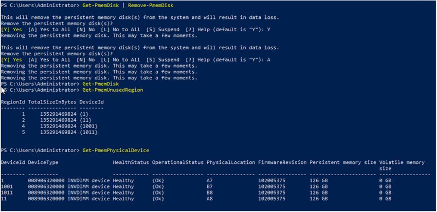
Contents

Chapter 1: Introduction................................................................................................................... 5
  System requirements............................................................................................................................................................ 5
  Terminology............................................................................................................................................................................ 6

Chapter 2: Change list.....................................................................................................................7

Chapter 3: Hardware....................................................................................................................... 8
  Server hardware configuration............................................................................................................................................ 8
  DIMM installation and removal.............................................................................................................................................8
  DCPMM hardware configuration........................................................................................................................................ 8
     DCPMM Recommended Topologies............................................................................................................................. 8
     CPU type and maximum memory limits...................................................................................................................... 15
     DCPMM mixing and population rules...........................................................................................................................15

Chapter 4: BIOS............................................................................................................................ 16
  BIOS configuration setting for Intel DCPMM...................................................................................................................16
     DIMM discovery............................................................................................................................................................. 16
  App-direct mode configuration...........................................................................................................................................17
     Create goal...................................................................................................................................................................... 17
     Region information......................................................................................................................................................... 18
  Memory mode configuration..............................................................................................................................................20
     Create goal..................................................................................................................................................................... 20

Chapter 5: DCPMM event reporting................................................................................................ 21
  Events during runtime......................................................................................................................................................... 21
  Events during boot time...................................................................................................................................................... 21

Chapter 6: iDRAC Intel DCPMM management..................................................................................24
  iDRAC GUI............................................................................................................................................................................ 24
     DCPMM firmware version............................................................................................................................................24
     DCPMM hardware status.............................................................................................................................................24
     DCPMM goal configuration using iDRAC GUI........................................................................................................... 25
     DCPMM remaining rated write endurance................................................................................................................ 26

Chapter 7: DCPMM security .......................................................................................................... 27
  Memory mode...................................................................................................................................................................... 27
  App-direct.............................................................................................................................................................................27
  Cryptographic erase and DCPMM sanitize......................................................................................................................28
     Crypto erase...................................................................................................................................................................29
     Sanitize............................................................................................................................................................................29

Chapter 8: DIMM configuration changes..........................................................................................31

                                                                                                                                                              Contents                   3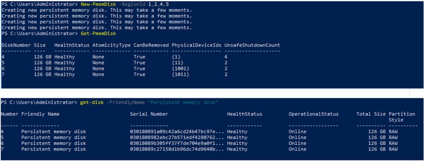
Chapter 9: Windows...................................................................................................................... 32
      PMEM in App-direct mode................................................................................................................................................ 32
         PMEM Disk management............................................................................................................................................. 33
         List PMEM physical disks and check their health status..........................................................................................34
         Create PMEM Disks...................................................................................................................................................... 34
         Remove PMEM disks....................................................................................................................................................35
      PMEM disk with interleave sets........................................................................................................................................ 35
         PMEM disk creation with interleave sets...................................................................................................................35
      PMEM in memory Mode ................................................................................................................................................... 36
      Windows troubleshooting and event monitoring.............................................................................................................36

    Chapter 10: Linux.......................................................................................................................... 38
      Identify and configure persistent memory device........................................................................................................... 38
         Listing DCPMM devices............................................................................................................................................... 38
         Create namespace.........................................................................................................................................................38
         Mount file system on namespace device................................................................................................................... 38
         Delete namespaces....................................................................................................................................................... 39
      Management utility..............................................................................................................................................................39
         Check DCPMM health status...................................................................................................................................... 39
      Linux errata.......................................................................................................................................................................... 39

    Chapter 11: VMware ESXi............................................................................................................... 41
      PMEM in App-direct mode................................................................................................................................................. 41
      PMEM in Memory mode.....................................................................................................................................................42
      PMEM health status........................................................................................................................................................... 42
      ESXi troubleshooting and maintenance............................................................................................................................42

    Chapter 12: System diagnostics..................................................................................................... 44

    Chapter 13: Firmware update......................................................................................................... 45
      Dell DUP update.................................................................................................................................................................. 45

4   Contents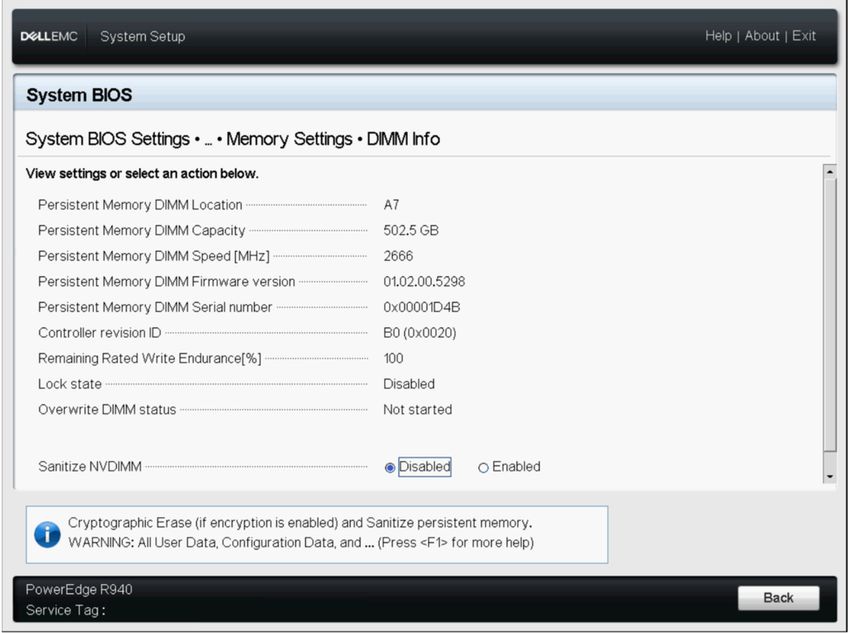
1
                                                                                                  Introduction
Dell EMC now offers Intel's Data Center Persistent Memory Modules (DCPMMs), a nonvolatile memory that has the same form factor as
a standard DDR4 DIMM.
DCPMMs come in three capacities: 128 GB, 256 GB, and 512 GB.
DCPMMs are installed in the memory slots of the server and are compatible with RDIMMs and LRDIMMs.
DCPMM can be configured in two modes:
•     Memory mode
•     App-direct mode
In Memory mode: DCPMMs act as volatile system memory and any RDIMMs or LRDIMMs installed operate as cache for the DCPMMs.
In App-direct mode: DCPMMs operate as byte addressable memory mapped persistent memory. DCPMMs and DRAM act as independent
memory resources. RDIMMs or LRDIMMs acts as volatile system memory. Applications can access persistent memory by using memory
load or store commands. Legacy applications that access storage as block devices can access persistent memory (PMEM) through the
PMEM block driver.
DCPMMs do not require an extra power supply or battery and are inherently persistent.
This document is intended to help customers understand the basics of Intel's DCPMM technology integrated in Dell PowerEdge systems.
It covers the fundamentals of installation and configuration of key settings for both the operating modes.
Topics:
•      System requirements
•      Terminology

System requirements
Table 1. System Requirements
    Component                                         Minimum version required

    System                                            R640, R740, R740xd, R840, R940, R940xa, MX740c and MX840c (2 and 4
                                                      socket systems)

    Processor                                         2nd Generation Intel Xeon Platinum or Gold processors

    BIOS                                              R640 - 2.3.10
                                                      R740/R740xd/R940 - 2.2.10
                                                      R840 / R940xa - 2.3.10
                                                      MX740c / MX840c - 2.3.10

    CPLD                                              R640 - 1.0.6
                                                      R740/R740xd - 1.0.8
                                                      R840 - 1.0.6
                                                      R940 - 1.0.4
                                                      R940xa - 1.0.6
                                                      MX740c / MX840c - 1.0.6

    iDRAC                                             3.34.34.34

                                                                                                              Introduction            5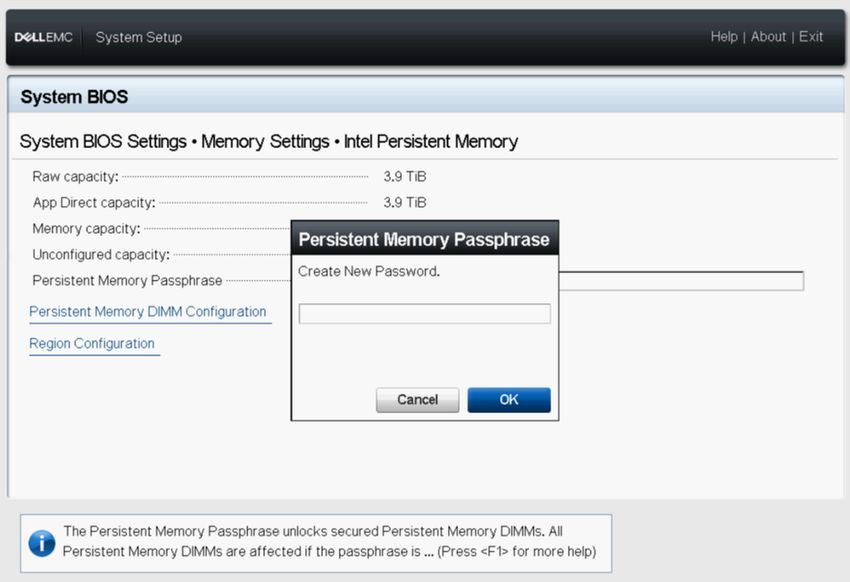
Table 1. System Requirements (continued)
Component                                  Minimum version required

DCPMM FW                                   Build # 5375

OS                                         Microsoft Windows 2019
                                           VMware ESXi 6.7 with EP10 (Build #13981272)
                                           Red Hat Enterprise Linux 7.6
                                           SUSE Linux Enterprise Server 15

Terminology
Table 2. Terminology
Terminology                                               Description
App-direct mode (AD)                                      Persistent memory is accessed directly by applications as byte-
                                                          addressable memory.

CLI                                                       Intel command-line interface in UEFI or Linux environment

DCPMM                                                     Intel Data Center Persistent Memory Module

GiB                                                       Gibibyte
                                                          1 GiB = 1024 MiB

GB                                                        Gigabyte
                                                          1 GB = 1000 MB

iMC                                                       Integrated Memory Controller

Interleave Set                                            Contiguous App-direct mode capacity that is created by
                                                          interleaving the persistent capacity of one or more DCPMMs.

x1 (by one) Interleave                                    Interleave set that includes App-direct capacity from only one
                                                          DCPMM pronounced "by one." This is essentially "Noninterleaved"

PM, PMEM                                                  Persistent Memory

Memory Mode (MM)                                          RDIMM or LRDIMM becomes cache for nonpersistent DCPMMs.

MiB                                                       Mibibyte
                                                          1 MiB = 1024 KB = 1048576 bytes

MB                                                        Megabyte
                                                          1 MB = 1000 KB = 1000000 bytes

Namespace                                                 A persistent memory device that is made available in the file
                                                          system.

TiB                                                       Tebibyte
                                                          1 TiB = 1024 GiB

TB                                                        Terabyte
                                                          1 TB = 1000 GB

6       Introduction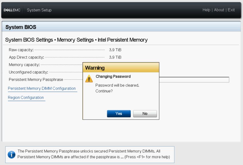
2
                                                           Change list
Table 3. Change list
Version                Changes
A01                    Original Version

A02                    Topics with new updates:
                       •   System Requirement
                       •   Server hardware configuration
                       •   DCPMM recommended topologies
                       •   Management utility

A03                    Topics with new updates:
                       •   System Requirement
                       •   Server hardware configuration

                                                              Change list   7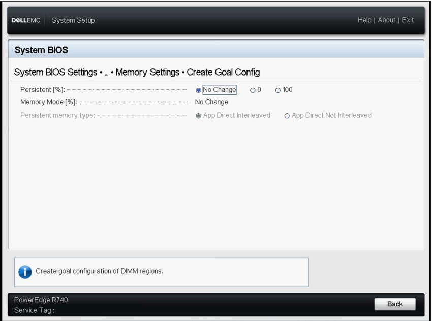
3
Hardware
Topics:
• Server hardware configuration
• DIMM installation and removal
• DCPMM hardware configuration
Server hardware configuration
DCPMM is supported in R640, R740/R740XD, R840, R940, R940xa, MX740c, and MX840c PowerEdge servers with second-generation
Intel Xeon Scalable Processors of Gold and Platinum grade. See DCPMM configurations for a list of fully supported and validated DCPMM
configurations in two-socket servers. Four-socket configurations are a direct scale up of two-socket configurations.
NOTE: For PowerEdge R840/R940/R940xa, 2400 W or 1600 W PSUs are required when Intel DCPMMs are present in
the system. When 1600 W PSUs are used, high line (~220 V) voltage is required. If these guidelines are not followed the
system may not have sufficient power holdup in an AC loss scenario to flush in-flight data contents to persistent media.
All systems that are built from Dell Technologies factories will be preconfigured to meet these guidelines.
DIMM installation and removal
Industry standard DIMM practices and procedures must be followed while handling, installing, or removing DCPMM memories.
For more details on procedures for installing/removing modules, see the "Standard Practices and Procedures - Module Insertion
Procedure for DIMM and miniDIMM Connectors" documentation by JEDEC.
JEDEC Standards (www.jedec.org): Document Number SPP-023B.
DCPMM hardware configuration
DCPMM Recommended Topologies
This section contains the high-level introduction on DCPMM configuration and provisioning concepts.
The following topologies are recommended per CPU socket. For multiple socket systems with more than one DCPMM, each socket
should be populated identically.
See the Installation and Service Manual for Memory installation guidelines of respective servers.
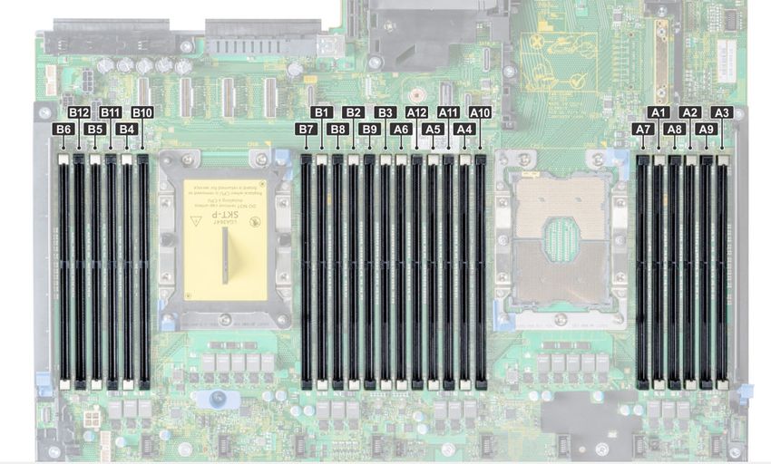
NOTE: The following image and table is for reference which displays the R740/R740XD CPU and DIMM slot locations.
8 Hardware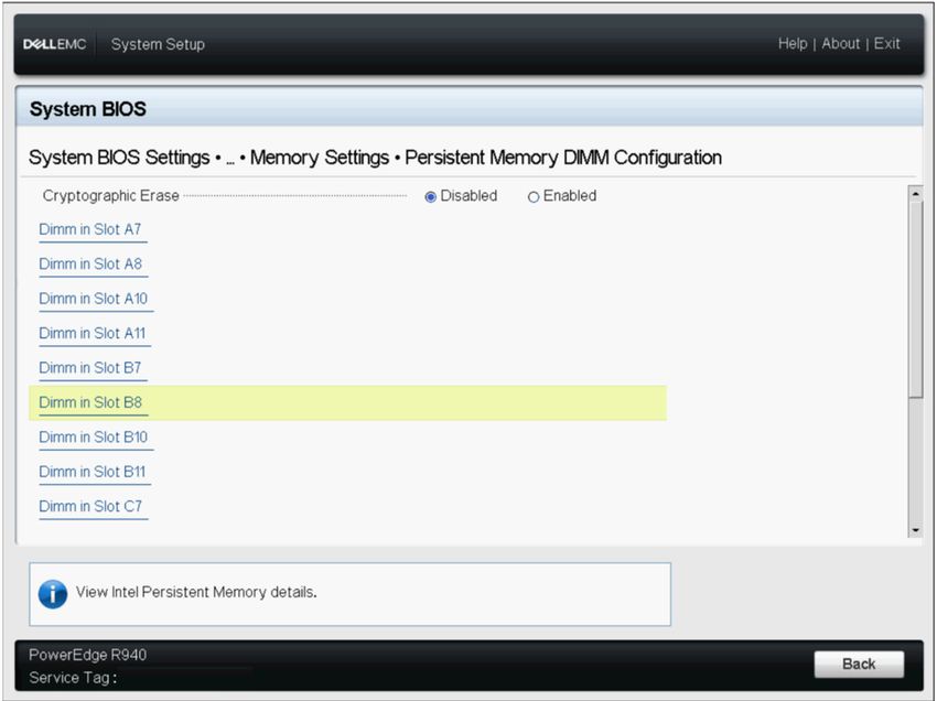
Figure 1. Memory Layout for R740/R740XD

Table 4. DCPMM configurations
Number DCPMM DRAM         DRAM        DCPMM OS         Total    Total     Ratio    Require   Support   Support
of CPUs Populati Populati Capacit     Capacit Memory   Memory   Memory    DRAM     s an M    ed in     ed in
in the  on       on       y (GB)      y (GB)  in       (GB)     per CPU   to       or L      App       Memory
Server                                        Memory            (GB)      Optane   CPU       Direct    Mode
                                              Mode                        Memory             Mode
                                              (GB)
1         128GB x   16GB x 4   64     256    256       320      320       1:4      No        Yes       Yes
          2

1         128GB x   16GB x 6   96     128    NA        224      224       1:1.3    No        Yes       No
          1

1         128GB x   16GB x 6   96     256    NA        352      352       1:2.7    No        Yes       No
          2

1         128GB x   16GB x 6   96     512    512       608      608       1:5.3    No        Yes       Yes
          4

1         128GB x   16GB x 6   96     768    768       864      864       1:8      No        Yes       Yes
          6

1         128GB x   32GB x 6 192      128    NA        320      320       1:0.7    No        Yes       No
          1

1         128GB x   32GB x 6 192      256    NA        448      448       1:1.3    No        Yes       No
          2

1         128GB x   32GB x 6 192      512    NA        704      704       1:2.7    No        Yes       No
          4

1         128GB x   32GB x 6 192      768    768       960      960       1:4      No        Yes       Yes
          6

1         128GB x   64GB x 6 384      128    NA        512      512       1:0.3    No        Yes       No
          1

2         128GB x   16GB x     192    128    NA        320      160       1:0.7    No        Yes       No
          1         12

2         128GB x   16GB x     192    256    NA        448      224       1:1.3    No        Yes       No
          2         12

                                                                                              Hardware           9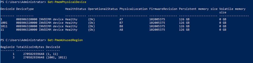
Table 4. DCPMM configurations (continued)
Number DCPMM DRAM         DRAM        DCPMM OS         Total    Total     Ratio    Require   Support   Support
of CPUs Populati Populati Capacit     Capacit Memory   Memory   Memory    DRAM     s an M    ed in     ed in
in the  on       on       y (GB)      y (GB)  in       (GB)     per CPU   to       or L      App       Memory
Server                                        Memory            (GB)      Optane   CPU       Direct    Mode
                                              Mode                        Memory             Mode
                                              (GB)
2        128GB x   16GB x 8   128     512     512      640      320       1:4      No        Yes       Yes
         4

2        128GB x   16GB x     192     512     NA       704      352       1:2.7    No        Yes       No
         4         12

2        128GB x   16GB x     192     1,024   1,024    1,216    608       1:5.3    No        Yes       Yes
         8         12

2        128GB x   16GB x     192     1,536   1,536    1,728    864       1:8      No        Yes       Yes
         12        12

2        128GB x   32GB x     384     128     NA       512      256       1:0.3    No        Yes       No
         1         12

2        128GB x   32GB x     384     256     NA       640      320       1:0.7    No        Yes       No
         2         12

2        128GB x   32GB x     384     512     NA       896      448       1:1.3    No        Yes       No
         4         12

2        128GB x   32GB x     384     1,024   NA       1,408    704       1:2.7    No        Yes       No
         8         12

2        128GB x   32GB x     384     1,536   1,536    1,920    960       1:4      No        Yes       Yes
         12        12

2        128GB x   64GB x     768     512     NA       1,280    640       1:0.7    No        Yes       No
         4         12

2        128GB x   64GB x     768     1,024   NA       1,792    896       1:1.3    No        Yes       No
         8         12

2        128GB x   64GB x     768     1,536   NA       2,304    1,152     1:2      L SKU     Yes       No
         12        12

2        128GB x   128GB x    1,536   1,536   NA       3,072    1,536     1:1      L SKU     Yes       No
         12        12

2        512GB x   32GB x     384     4,096   4,096    4,480    2,240     1:1.7    L SKU     Yes       Yes
         8         12

2        512GB x   32GB x     384     6,144   6,144    6,528    3,264     1:16     L SKU     Yes       Yes
         12        12

2        512GB x   64GB x     768     4,096   4,096    4,864    2,432     1:5.3    L SKU     Yes       Yes
         8         12

2        512GB x   64GB x     768     6,144   6,144    6,912    3,456     1:8      L SKU     Yes       Yes
         12        12

2        512GB x   128GB x    1,536   6,144   6,144    7,680    3,840     1:4      L SKU     Yes       Yes
         12        12

2        256GB x   16GB x     192     2,048   2,048    2,240    1,120     1:10.7   L SKU     Yes       Yes
         8         12

2        256GB x   32GB x     384     2,048   2,048    2,432    1,216     1:5.3    L SKU     Yes       Yes
         8         12

2        256GB x   32GB x     384     3,072   3,072    3,456    1,728     1:8      L SKU     Yes       Yes
         12        12

10    Hardware
Table 4. DCPMM configurations (continued)
Number DCPMM DRAM DRAM DCPMM OS Total Total Ratio Require Support Support
of CPUs Populati Populati Capacit Capacit Memory Memory Memory DRAM s an M ed in ed in
in the on on y (GB) y (GB) in (GB) per CPU to or L App Memory
Server Memory (GB) Optane CPU Direct Mode
Mode Memory Mode
(GB)
2 256GB x 64GB x 768 2,048 NA 2,816 1,408 1:2.7 L SKU Yes No
8 12
2 256GB x 64GB x 768 3,072 3,072 3,840 1,920 1:4 L SKU Yes Yes
12 12
2 256GB x 128GB x 1,536 3,072 NA 4,608 2,304 1:2 L SKU Yes No
12 12
4 128GB x 16GB x 384 2,048 2,048 2,432 608 1:5.3 No Yes Yes
16 24
4 128GB x 16GB x 384 3,072 3,072 3,456 864 1:8 No Yes Yes
24 24
4 128GB x 32GB x 768 2,048 NA 2,816 704 1:2.7 No Yes No
16 24
4 128GB x 32GB x 768 3,072 3,072 3,840 960 1:4 No Yes Yes
24 24
4 128GB x 64GB x 1,536 3,072 NA 4,608 1,152 1:2 L SKU Yes No
24 24
4 128GB x 128GB x 3,072 3,072 NA 6,144 1,536 1:1 L SKU Yes No
24 24
4 512GB x 32GB x 768 8,192 8,192 8,960 2,240 1:10.7 L SKU Yes Yes
16 24
4 512GB x 32GB x 768 12,288 12,288 13,056 3,264 1:16 L SKU Yes Yes
24 24
4 512GB x 64GB x 1,536 8,192 8,192 9,728 2,432 1:5.3 L SKU Yes Yes
16 24
4 512GB x 64GB x 1,536 12,288 12,288 13,824 3,456 1:8 L SKU Yes Yes
24 24
4 512GB x 128GB x 3,072 12,288 12,288 15,360 3,840 1:4 L SKU Yes Yes
24 24
4 256GB x 16GB x 384 4,096 4,096 4,480 1,120 1:10.7 L SKU Yes Yes
16 24
4 256GB x 16GB x 384 6,144 6,144 6,528 1,632 1:16 L SKU Yes Yes
24 24
4 256GB x 32GB x 768 4,096 4,096 4,864 1,216 1:5.3 L SKU Yes Yes
16 24
4 256GB x 32GB x 768 6,144 6,144 6,912 1,728 1:8 L SKU Yes Yes
24 24
4 256GB x 64GB x 1,536 4,096 NA 5,632 1,408 1:2.7 L SKU Yes No
16 24
4 256GB x 64GB x 1,536 6,144 6,144 7,680 1,920 1:4 L SKU Yes Yes
24 24
4 256GB x 128GB x 3,072 6,144 NA 9,216 2,304 1:2 L SKU Yes No
24 24
Hardware 11Table 5. Single socket DCPMM population
CPU 0
Channel 2 Channel 1 Channel 0 Channel 0 Channel 1 Channel 2
DCP DRAM A3 A9 A2 A8 A1 A7 A10 A4 A11 A5 A12 A6
MM
128GB 16GB x DCPM DRAM DRAM DRAM DRAM DCPM
x2 4 M M
128GB 16GB x DRAM DRAM DRAM DCP DRAM DRAM DRAM
x1 6 MM
128GB 16GB x DRAM DRAM DRAM DCP DCPM DRAM DRAM DRAM
x2 6 MM M
128GB 16GB x DRAM DRAM DCPM DRAM DCP DCPM DRAM DCPM DRAM DRAM
x4 6 M MM M M
128GB 16GB x DRAM DCPM DRAM DCPM DRAM DCP DCPM DRAM DCPM DRAM DCPM DRAM
x6 6 M M MM M M M
128GB 32GB x DRAM DRAM DRAM DCP DRAM DRAM DRAM
x1 6 MM
128GB 32GB x DRAM DRAM DRAM DCP DCPM DRAM DRAM DRAM
x2 6 MM M
128GB 32GB x DRAM DRAM DCPM DRAM DCP DCPM DRAM DCPM DRAM DRAM
x4 6 M MM M M
128GB 32GB x DRAM DCPM DRAM DCPM DRAM DCP DCPM DRAM DCPM DRAM DCPM DRAM
x6 6 M M MM M M M
128GB 64GB x DRAM DRAM DRAM DCP DRAM DRAM DRAM
x1 6 MM
Table 6. Dual socket DCPMM population
CPU 0 and CPU 1
Channel 2 Channel 1 Channel 0 Channel 0 Channel 1 Channel 2
DCP DRAM A3, A9, A2, B2 A8, A1, B1 A7, A10, A4, B4 A11, A5, A12, A6,
MM B3 B9 B8 B7 B10 B11 B5 B12 B6
128GB 16GB x DRAM DRAM DRAM DCP DRAM DRAM DRAM
x1 12 MM
only
on
CPU
0
128GB 16GB x DRAM DRAM DRAM DCP DRAM DRAM DRAM
x2 12 MM
128GB 16GB x DCPM DRAM DRAM DRAM DRAM DCPM
x4 8 M M
128GB 16GB x DRAM DRAM DRAM DCP DCPM DRAM DRAM DRAM
x4 12 MM M
128GB 16GB x DRAM DRAM DCPM DRAM DCP DCPM DRAM DCPM DRAM DRAM
x8 12 M MM M M
128GB 16GB x DRAM DCPM DRAM DCPM DRAM DCP DCPM DRAM DCPM DRAM DCPM DRAM
x 12 12 M M MM M M M
128GB 32GB x DRAM DRAM DRAM DCP DRAM DRAM DRAM
x1 12 MM
12 HardwareTable 6. Dual socket DCPMM population (continued)
CPU 0 and CPU 1
Channel 2 Channel 1 Channel 0 Channel 0 Channel 1 Channel 2
DCP DRAM A3, A9, A2, B2 A8, A1, B1 A7, A10, A4, B4 A11, A5, A12, A6,
MM B3 B9 B8 B7 B10 B11 B5 B12 B6
only
on
CPU
0
128GB 32GB x DRAM DRAM DRAM DCP DRAM DRAM DRAM
x2 12 MM
128GB 32GB x DRAM DRAM DRAM DCP DCPM DRAM DRAM DRAM
x4 12 MM M
128GB 32GB x DRAM DRAM DCPM DRAM DCP DCPM DRAM DCPM DRAM DRAM
x8 12 M MM M M
128GB 32GB x DRAM DCPM DRAM DCPM DRAM DCP DCPM DRAM DCPM DRAM DCPM DRAM
x 12 12 M M MM M M M
128GB 64GB x DRAM DRAM DRAM DCP DCPM DRAM DRAM DRAM
x4 12 MM M
128GB 64GB x DRAM DRAM DCPM DRAM DCP DCPM DRAM DCPM DRAM DRAM
x8 12 M MM M M
128GB 64GB x DRAM DCPM DRAM DCPM DRAM DCP DCPM DRAM DCPM DRAM DCPM DRAM
x 12 12 M M MM M M M
128GB 128GB x DRAM DCPM DRAM DCPM DRAM DCP DCPM DRAM DCPM DRAM DCPM DRAM
x 12 12 M M MM M M M
512GB 32GB x DRAM DRAM DCPM DRAM DCP DCPM DRAM DCPM DRAM DRAM
x8 12 M MM M M
512GB 32GB x DRAM DCPM DRAM DCPM DRAM DCP DCPM DRAM DCPM DRAM DCPM DRAM
x 12 12 M M MM M M M
512GB 64GB x DRAM DRAM DCPM DRAM DCP DCPM DRAM DCPM DRAM DRAM
x8 12 M MM M M
512GB 64GB x DRAM DCPM DRAM DCPM DRAM DCP DCPM DRAM DCPM DRAM DCPM DRAM
x 12 12 M M MM M M M
512GB 128GB x DRAM DCPM DRAM DCPM DRAM DCP DCPM DRAM DCPM DRAM DCPM DRAM
x 12 12 M M MM M M M
256G 16GB x DRAM DRAM DCPM DRAM DCP DCPM DRAM DCPM DRAM DRAM
Bx8 12 M MM M M
256G 32GB x DRAM DRAM DCPM DRAM DCP DCPM DRAM DCPM DRAM DRAM
Bx8 12 M MM M M
256G 32GB x DRAM DCPM DRAM DCPM DRAM DCP DCPM DRAM DCPM DRAM DCPM DRAM
B x 12 12 M M MM M M M
256G 64GB x DRAM DRAM DCPM DRAM DCP DCPM DRAM DCPM DRAM DRAM
Bx8 12 M MM M M
256G 64GB x DRAM DCPM DRAM DCPM DRAM DCP DCPM DRAM DCPM DRAM DCPM DRAM
B x 12 12 M M MM M M M
256G 128GB x DRAM DCPM DRAM DCPM DRAM DCP DCPM DRAM DCPM DRAM DCPM DRAM
B x 12 12 M M MM M M M
Hardware 13Table 7. Quad socket DCPMM population
CPU 0, CPU 1, CPU 2 and CPU 3
Channel 2 Channel 1 Channel 0 Channel 0 Channel 1 Channel 2
DCP DRAM A3, A9, A2, B2, A8, A1, A7, A10, A4, B4, A11, A5, A12, A6,
MM B3, B9, C2 B8, B1, C1 B7, B10, C4 B11, B5, B12, B6,
C3 C9 C8 C7 C10 C11 C5 C12 C6
128GB 16GB x DRAM DRAM DCPM DRAM DCP DCPM DRAM DCPM DRAM DRAM
x 16 24 M MM M M
128GB 16GB x DRAM DCPM DRAM DCPM DRAM DCP DCPM DRAM DCPM DRAM DCPM DRAM
x 24 24 M M MM M M M
128GB 32GB x DRAM DRAM DCPM DRAM DCP DCPM DRAM DCPM DRAM DRAM
x 16 24 M MM M M
128GB 32GB x DRAM DCPM DRAM DCPM DRAM DCP DCPM DRAM DCPM DRAM DCPM DRAM
x 24 24 M M MM M M M
128GB 64GB x DRAM DCPM DRAM DCPM DRAM DCP DCPM DRAM DCPM DRAM DCPM DRAM
x 24 24 M M MM M M M
128GB 128GB x DRAM DCPM DRAM DCPM DRAM DCP DCPM DRAM DCPM DRAM DCPM DRAM
x 24 24 M M MM M M M
512GB 32GB x DRAM DRAM DCPM DRAM DCP DCPM DRAM DCPM DRAM DRAM
x 16 24 M MM M M
512GB 32GB x DRAM DCPM DRAM DCPM DRAM DCP DCPM DRAM DCPM DRAM DCPM DRAM
x 24 24 M M MM M M M
512GB 64GB x DRAM DRAM DCPM DRAM DCP DCPM DRAM DCPM DRAM DRAM
x 16 24 M MM M M
512GB 64GB x DRAM DCPM DRAM DCPM DRAM DCP DCPM DRAM DCPM DRAM DCPM DRAM
x 24 24 M M MM M M M
512GB 128GB x DRAM DCPM DRAM DCPM DRAM DCP DCPM DRAM DCPM DRAM DCPM DRAM
x 24 24 M M MM M M M
256G 16GB x DRAM DRAM DCPM DRAM DCP DCPM DRAM DCPM DRAM DRAM
B x 16 24 M MM M M
256G 16GB x DRAM DCPM DRAM DCPM DRAM DCP DCPM DRAM DCPM DRAM DCPM DRAM
B x 24 24 M M MM M M M
256G 32GB x DRAM DRAM DCPM DRAM DCP DCPM DRAM DCPM DRAM DRAM
B x 16 24 M MM M M
256G 32GB x DRAM DCPM DRAM DCPM DRAM DCP DCPM DRAM DCPM DRAM DCPM DRAM
B x 24 24 M M MM M M M
256G 64GB x DRAM DRAM DCPM DRAM DCP DCPM DRAM DCPM DRAM DRAM
B x 16 24 M MM M M
256G 64GB x DRAM DCPM DRAM DCPM DRAM DCP DCPM DRAM DCPM DRAM DCPM DRAM
B x 24 24 M M MM M M M
256G 128GB x DRAM DCPM DRAM DCPM DRAM DCP DCPM DRAM DCPM DRAM DCPM DRAM
B x 24 24 M M MM M M M
512GB 64GB x DRAM DCPM DRAM DCPM DRAM DCP DCPM DRAM DCPM DRAM DCPM DRAM
x 12 12 M M MM M M M
512GB 128GB x DRAM DCPM DRAM DCPM DRAM DCP DCPM DRAM DCPM DRAM DCPM DRAM
x 12 12 M M MM M M M
256G 16GB x DRAM DRAM DCPM DRAM DCP DCPM DRAM DCPM DRAM DRAM
Bx8 12 M MM M M
14 HardwareTable 7. Quad socket DCPMM population (continued)
CPU 0, CPU 1, CPU 2 and CPU 3
Channel 2 Channel 1 Channel 0 Channel 0 Channel 1 Channel 2
DCP DRAM A3, A9, A2, B2, A8, A1, A7, A10, A4, B4, A11, A5, A12, A6,
MM B3, B9, C2 B8, B1, C1 B7, B10, C4 B11, B5, B12, B6,
C3 C9 C8 C7 C10 C11 C5 C12 C6
256G 32GB x DRAM DRAM DCPM DRAM DCP DCPM DRAM DCPM DRAM DRAM
Bx8 12 M MM M M
256G 32GB x DRAM DCPM DRAM DCPM DRAM DCP DCPM DRAM DCPM DRAM DCPM DRAM
B x 12 12 M M MM M M M
256G 64GB x DRAM DRAM DCPM DRAM DCP DCPM DRAM DCPM DRAM DRAM
Bx8 12 M MM M M
256G 64GB x DRAM DCPM DRAM DCPM DRAM DCP DCPM DRAM DCPM DRAM DCPM DRAM
B x 12 12 M M MM M M M
256G 128GB x DRAM DCPM DRAM DCPM DRAM DCP DCPM DRAM DCPM DRAM DCPM DRAM
B x 12 12 M M MM M M M
CPU type and maximum memory limits
Table 8. CPU type and maximum memory limits
CPU type Maximum memory supported
(Includes voltaile and persistent memory capacity)
All CPU SKUs 1 TB per CPU socket
M SKUs 2 TB per CPU socket
L SKUs 4.5 TB per CPU socket
DCPMM mixing and population rules
This section has general rules for DIMM mixing and population.
Each system must contain only one capacity of DCPMM. If you mix DCPMM capacities, an F1/F2 warning message is displayed. This is
not a supported configuration and must not be populated. The table DCPMM configurations replace the following rules:
Mixing rules
• DCPMM can be mixed with RDIMM, LRDIMM, and 3DS LRDIMM.
• Mixing DDR4 DIMM types (RDIMM, LRDIMM, 3DS LRDIMM), within a channel, iMC, socket, or across sockets are not supported.
• x4 and x8 DDR4 DIMMs can be mixed within a channel.
• Mixing DCPMM operating modes (App-direct, Memory mode) is not supported.
Population rules
• Maximum of one DCPMM per channel.
• If only one DIMM is populated on a channel, it should always go to the first slot in that channel (white slot).
• If a DCPMM and a DDR4 DIMM are populated on the same channel, always plug DCPMM on the second slot (black slot).
• If the DCPMM is configured in Memory Mode, the recommended DDR4 to DCPMM capacity ratio is 1:4 to 1:16 per iMC.
Hardware 154
BIOS
Topics:
• BIOS configuration setting for Intel DCPMM
• App-direct mode configuration
• Memory mode configuration
BIOS configuration setting for Intel DCPMM
DIMM discovery
All installed DCPMMs that the BIOS has discovered during system inventory is displayed in the BIOS Intel Persistent Memory tab:
Memory Settings > Persistent Memory > Intel Persistent Memory > Persistent Memory DIMM Configuration.
Figure 2. Persistent Memory screen
NOTE: DCPMMs are shown as DIMMs.
There is one entry for each DCPMM that is installed and the current health and status information for each DCPMM is displayed as:
16 BIOSFigure 3. Memory info
NOTE: Data is always assumed to be in units of MiB/GiB/TiB even if labeled MB/GB/TB. User capacity overhead is up to
2% of capacity (GiB). Another overhead may be required for Regions, Namespace, and Filesystems.
App-direct mode configuration
Create goal
Goal is created in BIOS.
To create a goal in BIOS, go to: Memory Settings > Persistent Memory > Intel Persistent Memory > Region Configuration >
Create Goal Config.
BIOS 17Figure 4. Goal configuration
The BIOS options determine how the goal is created and the DCPMMs are configured:
Persistent [%]:
• No Change - Does not apply any changes to the current goal.
• 100 - Creates a goal of 100% Persistent memory across the selected DCPMMs.
• 0 - Creates a goal of 0% Persistent memory across the selected DCPMMs. This operation configures all the DCPMM as Memory
mode.
Persistent memory type:
• App-direct Interleaved - Persistent mode interleave across the DCPMMs in a scoket. The DCPMMs are displayed one PMEM device
per socket in the operating system.
• App-direct Not Interleaved - Persistent mode is applied to DCPMM individually. Each DCPMM is displayed as an individual PMEM
device in the operating system.
After the goal is configured, and exited from BIOS, the goal will be created across the DCPMMs using the user specified settings during
the next boot.
Region information
Information about each region that is created during the Create Goal Config process can be accessed in the Region Configuration tab
in BIOS after a system reset:
Memory Settings > Persistent Memory > Intel Persistent Memory > Region Configuration.
18 BIOSFigure 5. Region configuration
The number of regions that are displayed depends on the number of processors in the system and not on the DCPMMs interleaved. If the
DCPMMs are configured as interleaved, one Persistent Memory Region is listed per socket in the system that has DCPMMs installed. If
the DCPMMs are configured as non-interleaved, one Persistent Memory Region is listed per DCPMM installed in the system.
Region information can be accessed by clicking each Persistent Memory Region link in the BIOS. Following is an example:
BIOS 19Figure 6. Region info
Memory mode configuration
Create goal
Goal is created in the BIOS.
To create a goal in BIOS, go to: Memory Settings > Persistent Memory > Intel Persistent Memory > Region Configuration >
Create Goal Config.
The BIOS options determine how the goal is created and the DCPMMs are configured:
Operation Target:
• Platform - Applies the goal to all the DIMMs in the system (recommended).
Persistent [%]:
• No Change - Does not apply any changes to the current goal.
• 100 - Creates a goal of 100% Persistent memory across the selected DCPMMs.
• 0 - Creates a goal of 0% Persistent memory across the selected DCPMMs. This operation configures all the DCPMM as Memory
mode.
20 BIOS5
DCPMM event reporting
When system detects DCPMM-related event either during runtime or POST, system will log the events in Server System Event Log(SEL)
and Life-Cycle Log(LCL). If an event is detected during boot time, system halts during the POST and user needs to press F1 to continue
the boot process.
NOTE: NVDIMM is frequently used in these messages. The term NVDIMM is generic to several different families of
persistent memory including DCPMM and not meant to indicate NVDIMM-N modules.
Topics:
• Events during runtime
• Events during boot time
Events during runtime
• MEM0001 : Multibit memory errors detected on a memory device at location .
Recommended Action : Reinstall the memory component. If the problem persists, contact technical support.
• MEM0701 : Correctable memory error rate exceeded for .
Recommended Action : Reinstall the memory component. If the problem continues, contact support.
• MEM9022 : A Non-Critical event was detected on the Non-Volatile Dual In-line memory module (NVDIMM) device in the slot
.
Recommended Action : If the issue persists, contact the service provider.
• MEM9040 : A Critical event was detected on the Non-Volatile Dual In-line memory module (NVDIMM) device in the slot .
Recommended Action : Remove and reinstall the Non-Volatile Dual In-line memory module (NVDIMM) device. If the issue persists,
contact the service provider. For information about removing and reinstalling the NVDIMM, see the system owner's manual on the
support site.
• MEM9061: An Information-Only event was detected on the Non-Volatile Dual In-line memory module (NVDIMM) device in the slot
. The NVDIMM is operating normally.
Recommended Action: No response action is required.
• MEM9073 : Unable to update firmware for the NVDIMM identified in the message.
Recommended Action: Retry the operation. If the issue persists, replace the NVDIMM, or contact your service provider. It is also
recommended that the system is upgraded to the latest BIOS.
Events during boot time
• UEFI0337 : Unable to update the firmware of NVDIMM located in the memory slot .
Recommended Action : Disconnect the input power to the system, wait for 30 seconds, and reconnect the power, Power on the
server and retry the operation. If the issue persists, replace the NVDIMM. For more information, see the product's owner's manual on
the support site.
• UEFI0338 : The firmware of NVDIMM located in the memory slot is successfully updated.
Recommended Action : N/A
• UEFI0345 : The erase operation on the nonvolatile DIMM with serial number in slot is successfully
completed.
Recommended Action: N/A
• UEFI0347 : Unable to initialize the memory because one or more errors have occurred during the NVDIMM initialization in the slot
.
Recommended Action : Manually remove and reinstall the NVDIMM. If the issue persists, contact your service provider. For more
information about removing and reinstalling an NVDIMM, see the product Installation and Service Manual available on the support site.
• UEFI0348 : The Remaining Rated Endurance value of NVDIMM installed in slot is less than or equal to 1%.
DCPMM event reporting 21Recommended Action : Power off the server and replace the NVDIMM immediately. For more information about the Remaining
Rated Endurance, see the product Installation and Service Manual available on the support site.
• UEFI0349 : Unable to initialize the NVDIMMs because different types of NVDIMM SKUs or controller revisions are installed.
Recommended Action : Power off the server and replace the NVDIMMs to ensure all NVDIMM SKUs or controller revisions are
same. For more information about the NVDIMMs SKUs or controller revision, see the product Installation and Service Manual available
on the support site.
• UEFI0350 : The NVDIMM in the memory slot is replaced or removed from a previously configured Persistent Memory
(PM) region.
Recommended Action : Create a new Persistent Memory (PM) region. For more information about creating a PM region, see the
platform Installation and Service Manual available on the support site.
• UEFI0351: The NVDIMMs on socket are installed in an unsupported (configuration) manner. Major Error code
Minor Error code . Data in the Persistent Memory (PM) region may not be
accessible.
Recommended Action : For more information about creating a PM region, see the platform Installation and Service Manual available
on the support site.
• UEFI0352 : Unable to use the Persistent Memory (PM) region configuration of the NVDIMM in the memory slot .
Recommended Action : Verify the NVDIMM population configuration and retry the operation. For more information about
NVDIMMs, see the platform Installation and Service Manual available on the support site.
• UEFI0353 : The Persistent Memory (PM) configuration information of the NVDIMM in the memory slot is corrupted
because the checksum or the header type is not valid.
Recommended Action : Remove and reinstall the NVDIMMs or create a new Persistent Memory (PM) configuration. If the issue
persists, contact your service provider. For more information about creating a PM region, see the platform Installation and Service
Manual available on the support site.
• UEFI0354 : The DDR4 memory to NVDIMM ratio on the socket is not optimal to provide minimal performance
requirement.
Recommended Action : Reconfigure DDR4 memory to a ratio between 1:4 and 1:16. For more information about reconfiguring DDR4
memory, see the platform Installation and Service Manual available on the support site.
• UEFI0355 : All the NVDIMMs are disabled because the value of memory capacity of all the installed NVDIMMs has exceeded the
maximum value supported by the processor.
Recommended Action : Reconfigure the processor to support the value of memory capacity of all the installed NVDIMMs. For more
information about reconfiguring the processor, see the platform Installation and Service Manual available on the support site.
• UEFI0356 : The data in the Persistent Memory DIMM located in memory slot is not accessible because the DIMM is
locked and the passphrase is incorrect.
Recommended Action : Update the Persistent Memory Passphrase to the correct passphrase or perform a Secure Erase operation
on the Dual inline memory module (DIMM). Secure erase, erases all persistent data.
• UEFI0357 : The Cryptographic Erase operation on the Intel Persistent Memory DIMM with serial number in slot is successfully completed.
Recommended Action : N/A
• UEFI0358 : Unable to complete the Cryptographic Erase operation on the Intel Persistent Memory DIMM with serial number in slot .
Recommended Action : Retry the operation. If the issue persists, contact your service provider.
• UEFI0359 : The Overwrite DIMM operation on the Intel Persistent Memory DIMM with serial number in slot is successfully completed.
Recommended Action : N/A
NOTE: This is part of the DCPMM Sanitize function.
• UEFI0360 : Unable to complete the Overwrite DIMM operation on the Intel Persistent Memory DIMM with serial number in slot .
Recommended Action : Retry the operation. If the issue persists, contact your service provider.
NOTE: This is part of the DCPMM Sanitize function.
• UEFI0361 : The Factory Default operation for the Intel Persistent Memory DIMMs in the system has completed successfully.
Recommended Action : N/A
• UEFI0362 : Unable to complete the Factory Default operation on the Intel Persistent Memory DIMMs.
Recommended Action : Retry the operation. If the issue persists, contact your service provider.
22 DCPMM event reporting• UEFI0367 : The Create Goal operation on the Intel Persistent Memory DIMMs is successfully completed.
Recommended Action : N/A
• UEFI0368 : Unable to complete the Create Goal operation on the Intel Persistent Memory DIMMs.
Recommended Action : Retry the operation. If the issue persists, contact your service provider.
• UEFI0369 : The Complex Programmable Logic Device (CPLD) is successfully armed for the Asynchronous DRAM Refresh (ADR)
signal.
Recommended Action : N/A
• UEFI0370 : The Complex Programmable Logic Device (CPLD) cannot arm for the Asynchronous DRAM Refresh (ADR) signal. It
might be due to Intel Persistent Memory DIMMs failed to initialize.
Recommended Action : Reboot the system. If the issue persists, contact your service provider.
• UEFI0372 : The Remaining Rated Endurance value of the NVDIMM installed in the slot is equal to 0%.
Recommended Action : Turn off the server and replace the NVDIMM immediately. For more information about the Remaining Rated
Endurance, see the product Installation and Service Manual available on the support site.
• UEFI0373 : The NVDIMM installed in slot requires a maintenance.
Recommended Action : Consider replacing the DIMM during the next maintenance cycle. For more information about the NVDIMM
Health Status, see the product Installation and Service Manual available on the support site.
• UEFI0374 : The NVDIMM installed in slot is in critical condition.
Recommended Action : Power off the server and replace the NVDIMM immediately. For more information about the NVDIMM
Health Status, see the product Installation and Service Manual available on the support site.
• UEFI0375 : Unable to apply the Persistent Memory (PM) region configuration of the NVDIMM in the memory slot .
Recommended Action : Verify the NVDIMM population configuration and retry the operation. For more information about
NVDIMMs, see the platform Installation and Service Manual available on the support site.
• UEFI0376 : All the NVDIMMs are disabled because the installed processor does not support the Intel Persistent Memory DIMMs.
Recommended Action : Reconfigure the processor to support the Intel Persistent Memory DIMMs. For more information about
reconfiguring the processor, see the Installation and Service Manual of the system available on the support site.
• UEFI0377 : The Non-Volatile Dual In-Line memory module (NVDIMM) in the memory slot has encountered a transient
fatal failure during the previous boot.
Recommended Action : Remove and reinstall the Non-Volatile Dual In-line memory module (NVDIMM) device. If the issue persists,
contact your service provider. For more information about installation and removal, see the Installation and Service Manual of the
server available on the support site.
• UEFI0378 : The Non-Volatile Dual In-Line memory module (NVDIMM) in the memory slot has encountered a thermal
shutdown event during the previous boot.
Recommended Action : Do one of the following: 1) Power off the server. 2) Disconnect the input power, wait for 30 seconds, and
then reconnect to the power source. 3) Power on the server. 4) If the issue persists, contact your service provider.
• PWR2281 : Unable to perform the memory arming operation because the PSU configuration of the server is insufficient to guarantee
data flush time in the event of power loss.
Recommended Action : Do the following and retry the operation:
○ Turn off the server.
○ Ensure the PSUs are installed as recommended in the user guide.
○ Turn on the server.
For more information on supported PSUs, see the Installation and Service Manual of the system available on the support site.
DCPMM event reporting 236
iDRAC Intel DCPMM management
Topics:
• iDRAC GUI
iDRAC GUI
DCPMM firmware version
DCPMM FW version is displayed under System > Inventory > Firmware inventory tab.
Figure 7. DCPMM firmware version
DCPMM hardware status
Select the Memory link on the Dashboard to get more information about memory health.
DCPMM hardware status is displayed under System > Inventory > Hardware inventory tab.
24 iDRAC Intel DCPMM managementFigure 8. DCPMM hardware status
DCPMM goal configuration using iDRAC GUI
1. Log on to iDRAC GUI interface.
2. Navigate to Configuration > BIOS settings > Memory settings > Persistent Memory Settings tab.
Figure 9. DCPMM goal configuration using iDRAC GUI
3. Navigate to Intel Persistent Memory > Region Configuration > Create Goal Config.
iDRAC Intel DCPMM management 25Figure 10. DCPMM goal configuration
4. Change Persistent percentage as 100% to configure Intel DCPMM into 100% App-direct Mode and 0% to configure the DIMMs into
100% memory mode.
NOTE: The Persistent memory type field is for configuring a new goal. It is not for reading the status of the current
goal. Use instructions under DCPMM Hardware Status to confirm current configuration.
5. Click Apply and reset the system.
6. Goals will be applied into operating modes (either App-direct or Memory) in the next power cycle.
DCPMM remaining rated write endurance
DCPMM remaining lifetime is reflected as Remaining Rated Write Endurance in the IDRAC GUI. It is displayed under System >
Overview > Memory.
Key limitations and feature information:
• The feature does not work if the system is halted in BIOS such as the BIOS setup. If the system stays in this state for long periods, the
endurance for all DCPMM reports as 0% as status cannot be retrieved. To resolve, the user needs to boot into the operating system
and wait up to 24 hours for the next automatic poll of status.
• The values do not change frequently and are polled once per day. If the user performs a System Erase or Repurpose and Retire, it
destroys the stored values for this feature. DCPMM will be displayed as 0% after such an operation until the next automatic poll within
24 hours.
Figure 11. Individual memory details
26 iDRAC Intel DCPMM management7
DCPMM security
Topics:
• Memory mode
• App-direct
• Cryptographic erase and DCPMM sanitize
Memory mode
In Memory mode DCPMMs operate as volatile system memory. User passphrase is not supported and this BIOS setting will be greyed out.
App-direct
Users have the option to enable Passphrase protection of DCPMM regions. The intent of the passphrase is to protect against
unauthorized access to data stored on the DCPMM region. If the DCPMMs are moved from one server to another server, the user must
re-enter the security passphrase in BIOS setup before the data can be accessed.
If the customer chooses to enable passphrase protection or not, BIOS locks the DCPMM before booting to the operating system or UEFI
Shell. This means that all security changes are controlled by the Dell BIOS and operating system level security changes including
Passphrase management and DCPMM erasing functions will not be supported. All these functions must be driven through the BIOS setup.
NOTE: As mentioned in section DIMM Configuration Changes, the only migration scenario that is supported is a slot for
slot replacement between motherboards. Adding or removing individual DCPMM for any reason will likely result in data
loss and trigger the need for goal and security reconfiguration.
The passphrase to lock or encrypt the data at rest on the DCPMM in App-direct is configurable in the BIOS setup. If the field is not empty,
every boot the supplied passphrase is used to attempt to unlock all DCPMM in the system.
The following use cases are related to unsupported migration scenarios:
• When changing passphrase in the BIOS setup, the existing passphrase only needs to be entered once per session. Entering and
existing the field multiple times will not reprompt for the passphrase again (until the next boot session).
• Passphrase can be cleared by entering empty string in BIOS setup passphrase field.
NOTE: To clear the passphrase, keep the passphrase field blank and hit Enter.
DCPMM security 27Figure 12. Clearing Passphrase Cryptographic erase and DCPMM sanitize There are two ways to erase the persistent region content (App-direct) of the DCPMM: • Crypto Erase • Sanitize 28 DCPMM security
Both erase methods can be executed using BIOS setup options. User can choose to perform an erase on all or a subset of installed
DCPMMs.

Crypto erase
The Crypto Erase function erases the App-direct Region Key (PM-RK) forcing the system to reboot.
Cryptographic erase option can be accessed by going to: System BIOS Settings > Memory Settings > Persistent Memory > Intel
Persistent Memory > Persistent Memory DIMM Configuration

Figure 13. Crypto erase

    NOTE: It is not recommended to erase part of DCPMMs installed on the system when App-direct interleaved region is
    configured. This operation renders all the data on the interleave set invalid.

Sanitize
DCPMM Sanitization is a long operation which runs on all the selected persistent memories in parallel.
This process does a cryptographic erase first and writes zeros to all accessible persistent media regions on the DCPMM. Also, it destroys
any existing memory goal contents.
The region of the DCPMM where the goal is configured will be empty and on the next boot the memory will default to 100% Memory
Mode. If the system does not have the proper ratio of RDIMM or LRDIMM memory to DCPMM, it is expected on the following boot for an
error to occur indicating that the ratio is not optimized.
Sanitize option can be accessed by going to: System BIOS Settings > Memory Settings > Persistent Memory

Figure 14. Sanitize

                                                                                                              DCPMM security            29
Sanitize can take up to 15 minutes with fully loaded 128 GB DIMM configuration, 30 minutes with 256 GB and 1 hour with 512 GB.
NOTE: Sanitize is not supported when DCPMMs are configured in Memory mode. When the Sanitize operation is
running, a prompt appears in BIOS indicating an Overwrite. Overwrite is the name for the second firmware command
that is conducted. The first command which happens quickly and will not be displayed on-screen is the Crypto Erase
(firmware command name is "Secure Erase").
30 DCPMM security8
DIMM configuration changes
The following DCPMM migration scenarios are supported:
• Replacement of System Board due to failure
All DIMMs must be re-populated in the exact same slots. DCPMMs and data content will be available for customer application access
after the board has been restored to the same configuration as the original board. System Restore will automatically restore the BIOS
configuration on the replacement board, including the DCPMM Passphrase, if it is set.
• Replacing bad DIMM
In the case of a failed DCPMM, any data associated with the DCPMM would be lost. The region and interleave set on the failed
DCPMM must be recreated once it is replaced. The user must use BIOS Setup to create a new goal for the affected DCPMM.
NOTE: Any remaining persistent memory data on Intel DCPMM must be backed up prior creating a goal. The goal
creation process deletes all namespaces, regions, and data stored on the DCPMMs on the selected CPUs. If a Security
Passphrase is enabled, the new persistent memory region is protected with the system DCPMM passphrase.
NOTE: Adding or removing DCPMMs to an existing DCPMM configuration is not supported, and not validated. It is
recommended that customers back up all DCPMM data to another storage device before making any DCPMM
configuration changes. Once the server is reconfigured to the new DCPMM configuration, the customer can create a
goal configuration and restore data back to DCPMMs.
DIMM configuration changes 319
Windows
Dell EMC supports Intel DCPMM with Microsoft Windows 2019 in Memory mode and App-direct mode.
NOTE: Keep Windows updated with the monthly cumulative updates.
Topics:
• PMEM in App-direct mode
• PMEM disk with interleave sets
• PMEM in memory Mode
• Windows troubleshooting and event monitoring
PMEM in App-direct mode
In App-direct mode, Windows creates two types of device objects for DCPMMs :
• Physical INVDIMM device
• Logical Persistent Memory disk
Logical persistent memory disks get created after creating namespaces on PMEM Physical disks.
When the system first boots into the Operating System, PMEM devices get enumerated as physical INVDIMM devices under Memory
Devices in Device Manager.
Figure 15. Memory Devices in Device Manager
After PMEM disks are configured over PowerShell, logical persistent memory disks show under Device Manager.
32 WindowsFigure 16. Memory Devices in Device Manager
PMEM Disk management
Windows currently supports only one namespace per interleave set (this is independent of the number of physical devices in the interleave
set).The option to interleave DCPMMs can be selected during goal creation as described in App Direct and Memory mode configurations.
PMEM disks have to be created with the help of "New-Pmemdisk" command by providing relevant region IDs. Once PMEM disks are
configured, PMEM volumes can be used as normal disks.
Windows supports the following PowerShell cmdlets to manage persistent memory:
• Get-PmemDisk
○ Returns one or more logical persistent memory disks.
○ The returned object has information about size, atomicity type, health status, and underlying physical devices.
• Get-PmemPhysicalDevice
○ Returns one or more physical persistent memory devices (NVDIMMs).
○ The returned object has information about size(s), RFIC, device location, and health/operational status.
• New-PmemDisk
○ Creates a new disk out of a given unused region.
○ Writes out the labels to create the namespace then rebuilds the SCM stacks to expose the new logical device.
○ Optional parameters:
▪ FriendlyName gives the persistent memory disk a friendly name. Default is “PmemDisk”.
▪ AtomicityType lets you set BTT. Default is “none”.
• Remove-PmemDisk
○ Removes the given persistent memory disk. It accepts the output of Get-PmemDisk.
○ Deletes the namespace’s labels and then rebuilds the SCM stacks to remove the logical device.
○ Requires user confirmation, which can be overridden with Force.
• Get-PmemUnusedRegion
○ Returns aggregate PMEM regions available for provisioning a logical device.
○ Returned object has a unique region ID, total size, and list of physical devices that contribute to the unused region.
• Initialize-PmemPhysicalDevice
○ Writes zeroes to the label storage area, writes new label index blocks, and then rebuilds the SCM stacks to reflect the changes.
Windows 33○ Requires user confirmation, which can be overridden with Force.
○ This cmdlet is intended as a “big hammer” recovery mechanism. It is not recommended for normal use.
List PMEM physical disks and check their health status
The following image displays command usage to list all usage to list all PMEM physical devices and get their health. Physical location gives
the location of the DIMM on the motherboard.
Figure 17. List PMEM Physical Disks and their health status
NOTE: If Health Status is not Healthy and Operational Status is not OK, the issue needs to be rectified before creating
namespaces. Customers can run into this scenario if DCPMMs were previously used with another operating system and
were booted with Windows without Sanitizing. If such a scenario occurs, right-click and uninstall all the Memory devices
and Persistent Memory disks from Device Manager and then scan for HW changes under Action in Device Manager. This
resolves any issues with the driver stack.
Create PMEM Disks
Figure 18. Create PMEM Disks
34 WindowsRemove PMEM disks
Figure 19. Remove PMEM disks
Windows 2019 does not support redundant volume creation on PMEM disks by using Windows VDS (Virtual disk service).
In order to create redundant volumes, use the storage spaces method.
For information about storage spaces method refer to: https://docs.microsoft.com/en-us/windows-server/storage/storage-spaces/
deploy-standalone-storage-spaces.
PMEM disk with interleave sets
Interleaved sets can often be created to make multiple persistent memory devices be displayed as a single logical disk to windows server.
For PMEM Disk with the interleave set, "App-direct Interleave" should be selected during goal configuration.
PMEM disk creation with interleave sets
When Interleave set is enabled, BIOS assigns single Region Id for DCPMMs connected to the same processor.
Figure 20. PMEM Disk creation with interleave sets
In above example two Interleave sets have been created, one Interleave set using slots A7, A8 and another Interleave set using B7, B8.
We can create PMEM Disk also using Region id.
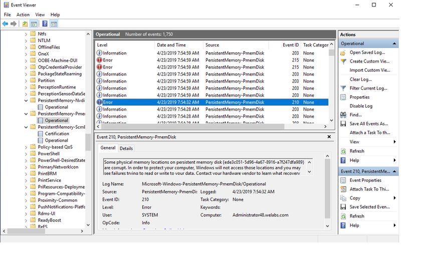
Windows 35Figure 21. PMEM Disk creation using Region id PMEM in memory Mode When Intel DCPMM is configured in memory mode, operating system sees it as system memory. Persistent memory size is shown as zero and volatile memory size accounts for the entire size of the DCPMM. Figure 22. PMEM in memory Mode Windows troubleshooting and event monitoring If any of the PMEM physical devices or logical devices are not functioning properly, it is suggested to check Windows event logs. To see the logs, open Event Viewer and navigate to : Applications and Services Logs > Microsoft > Windows The names of all persistent memory drivers logs start with “PersistentMemory.” All runtime errors are logged to the “Operational” log. This log captures the complete operation of PMEM physical device(NVDIMM) and PMEM logical device (PMEMDisk). 36 Windows
You can also read