TTD Series Configurable Fault Annunciator - Installation and Operations Manual - FW Murphy
←
→
Page content transcription
If your browser does not render page correctly, please read the page content below
TTDSeries Configurable
Fault Annunciator
Installation and Operations Manual
00-02-0697
2018-10-22
Section 50
FW Murphy has made efforts to ensure the reliability of the TTD System and to
recommend safe usage practices in system applications. Please note that in any
application, operation and controller failures can occur. These failures may result
in full control outputs or other outputs, which may cause damage to or unsafe
conditions in the equipment or process connected to the TTD system.

Good engineering practices, electrical codes and insurance regulations require
that you use independent external protective devices to prevent potentially
dangerous or unsafe conditions. Assume that the TTD system can fail with outputs
full on, outputs full off or that other unexpected conditions can occur.

Please read the following information before installing the TTD annunciator.

This installation information is intended for all TTD Series models. A visual
inspection of this product before installation for any damage during shipping is
recommended.

Disconnect all power and be sure machine is inoperative before beginning
installation.

Installation is to be done only by qualified technician.

Observe all Warnings and Cautions at each section in these instructions.

Device shall be wired in accordance with Class I, Division 2 wiring methods.

This equipment is suitable for use in Class I, Division 2, Groups B, C and D
hazardous areas.

WARNING – Explosion Hazard – Substitution of components may impair
suitability for Class I, Division 2.

Please contact FW Murphy immediately if you have any questions.
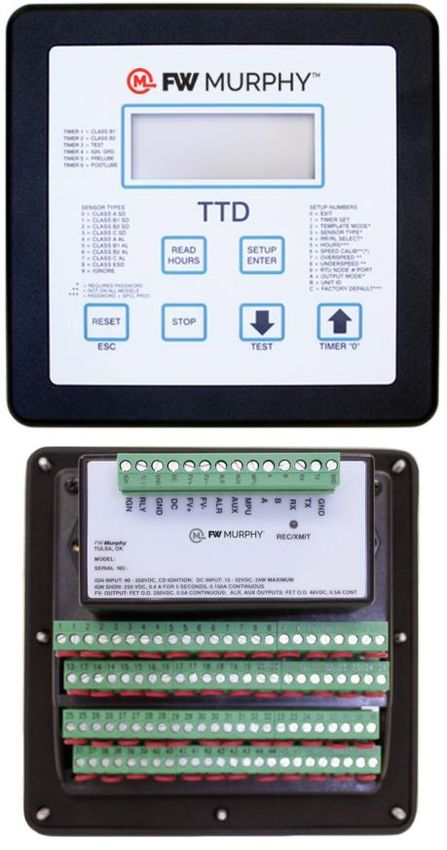
Table of Contents
Product Description ...................................................................................................................1

      Display Head (TTD-H) ..................................................................................................1
      Power Supply ...............................................................................................................2
      Dimensions ..................................................................................................................2
Installation ...................................................................................................................................3

      Mounting the Unit .........................................................................................................3
      Installation Diagram for the TTD Display ......................................................................4
      Typical Installations for TTD Power and Control Inputs/Outputs ..................................6
      TTD G-Lead Choke Installation Instruction ..................................................................9
      Backup Battery Replacement .....................................................................................10
      Initial Power-up ..........................................................................................................12
Product Features......................................................................................................................13

      The Display ................................................................................................................14
      Front Panel Key Functionality ....................................................................................15
      TTD Keypad Features ................................................................................................15
      Operational Display Messages...................................................................................19
      Backlight used as Status Indication ............................................................................21
Configuration / Setup of the TTD Annunciator ....................................................................22

      Navigating the TTD Front Panel .................................................................................22
      Entering Setup Mode .................................................................................................23
      Setup 1 – Timer Setup ...............................................................................................25
      Setup 2 – Sensor Mode .............................................................................................27
      Setup 3 – Sensor Type ..............................................................................................30
      Setup 4 – Remote Reset Remote Lockout Select and No-Flow Enable Delay ..........32
      Setup 5 - Hourmeters .................................................................................................34
      Setup 6 – Speed Calibration ......................................................................................35
      Setup 7 – Tachometer Overspeed Option ..................................................................37
      Setup 8 – Tachometer Underspeed Option ................................................................38
      Setup 9 – Communication Settings ............................................................................39
Setup A – Output Mode ..............................................................................................40
      Setup B – Unit Identification (ID) ................................................................................41
      Setup C – Factory Default ..........................................................................................42
      Voltage Readings .......................................................................................................43
      Software Version ........................................................................................................44
Communications ......................................................................................................................45

      Communications Port .................................................................................................45
      Modbus Register Address Listings .............................................................................46
Specifications ...........................................................................................................................49

TTD Replacement Parts and Assemblies .............................................................................51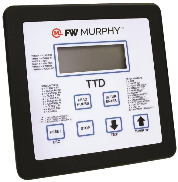
Product Description The TTD product is a solid-state fault annunciator and shut-down control system designed to protect engines, compressors and their associated equipment. The TTD monitors 48 normally open and/or normally closed sensors. Each of the 48 channels can be configured for Shutdown or Alarm Only. Any channel can be locked out by one of the two Start-Run timers or configured as Class C, ESD or Ignore. The annunciator provides logic for both closing of a fuel valve and grounding of an ignition after a time delay. Incorporated in the TTD non-volatile memory: Run Hours/Elapsed Time Meter (hours roll over at 99,999) Last 10 Shutdowns with associated run hours Last 4 Alarms with associated run hours Optional Features (Model Dependent): Pre/Post lube timed functionality Tachometer w/ Overspeed and Underspeed setpoints Lubricator No-Flow detection for up to 4 pulsing proximity switches Display Head (TTD-H) The Display Head shows operational and configuration data. Configuration parameters are entered via keypad or transferred using PC and Mconfig™ software. The operator interface will accept digital inputs directly on the back of the unit. Power is provided to the Display Head via a direct-mounted power supply or a cable connecting to a remote mounted power supply. The display head contains the microprocessor, the Liquid Crystal Display (LCD), the membrane keys for configuring the sensors inputs and the sensor input terminal blocks. The TTD liquid crystal display annunciates any fault from the sensor channel, displays engine speed and run hours/elapsed time. Other features for the TTD model are: built-in Test Mode to test the sensor circuits without shutting down; Pre-lubrication and Post-lubrication timers; and onboard backup battery to retain the fault display after shutdown on ignition-powered units. Section 50 00-02-0697 2018-10-22 -1-
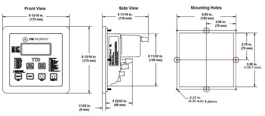
Power Supply
The Power Input and Control Output Terminals are mounted on the Plug-in Power Supply
(PSU-2). The Power Supply also includes a RS485/RS232 serial communication port
(MODBUS RTU slave) to interface with micro-controllers, PCs, PLCs and/or communication
and control systems. The serial communication provides read and write register capability with
selectable baud rates up to 38,400 bps.
All PSU-2 Power Supply models are reverse polarity protected and can be powered by 10-
32vdc or 90- 400vdc negative ground CD ignition. The TTD annunciator is fully operable with
the internal battery. The external DC power enables communications support and turns on the
display backlight.

Dimensions
TTD Display Head

Power Supply

Section 50                                                                        00-02-0697
2018-10-22                                   -2-
Installation
Mounting the Unit
The TTD head was designed to be mounted within a weatherproof enclosure. It is intended for
mounting in a flat panel. A square mounting hole of 5-1/2 in. (140 mm) and 4 mounting screw
holes are needed.
WARNING! Perform the mounting operation with power source off.
Stud Tightening Pattern
The following stud tightening instructions are required to maintain the IP66 rating when
installation requires the display to be mounted in an enclosure door exposed to atmospheric
conditions.
Stud tightening pattern should be followed:
1. Top left corner
2. Bottom right corner
3. Top right corner
4. Bottom left corner
5. Top center
6. Bottom center
7. Right center
8. Left center
Tighten holding nuts to 9 in. /lbs.
Section 50 00-02-0697
2018-10-22 -3-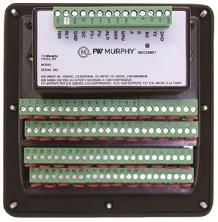
Installation Diagram for the TTD Display

Section 50                                 00-02-0697
2018-10-22                           -4-
Section 50         00-02-0697
2018-10-22   -5-
Typical Installations for TTD Power and Control Inputs/Outputs

Section 50                                                       00-02-0697
2018-10-22                           -6-
Section 50         00-02-0697
2018-10-22   -7-
Section 50         00-02-0697
2018-10-22   -8-
TTD G-Lead Choke Installation Instruction
      IMPORTANT: This installation is recommended when connecting an ignition
      primary lead to the TTD Annunciator to avoid potential electrical noise problems.
      This choke has been specifically selected for the application.
      The choke (FW Murphy part number 50000774) is shipped with each TTD
      annunciator.

                         1. Open the choke and lay it on the table.

                         2. Lay the wire across the inside of the choke as shown.

                         3. Wrap the wire around the outside of the choke as shown.

                         4. Wrap the wire back across the inside of the choke as shown.
                         The wire should lay next to the wire from step 2.

                         5. While holding the wires, carefully close the choke as shown.
                         Be careful not to pinch the wire when closing the choke.

                               NOTE: Keep the wire loops on the outside of the
                               choke as small as possible.

Section 50                                                                          00-02-0697
2018-10-22                                   -9-
Backup Battery Replacement
WARNING! Before disconnecting or connecting equipment, switch
the power OFF and, if possible, lock it out. Assure the area is in a
non-hazardous condition before beginning the installation of any
new equipment or repairing existing equipment. Bypassing these
precautions may present an environment in which explosive
hazards are present. If you are working in a hazardous location,
take the appropriate precautions to assure the safety of all
personnel and equipment.
The TTD Annunciator contains a Backup Power Battery (shipped loose with
the TTD Annunciator) located in the power supply module.
While this battery has a potential life of up to 1 year, it may require replacement. The LOW
BATT icon will appear when the internal backup battery voltage is below 5.0 volts. If the battery
is missing or the voltage falls below 4.6 volts, the LOW BATT icon will
blink. Replace the battery when the LOW BATT icon displays in the
lower left corner.
NOTE: Internal backup battery is not used during normal operation. Backup
battery supplies power to operate TTD Annunciator when CD Ignition is the only
source of power and it is not operating (Shutdown), or the user supplied +DC
power source has been disconnected.
When CD Ignition or DC voltage is present, power is not consumed from the internal backup
battery.
Section 50 00-02-0697
2018-10-22 - 10 -To replace the battery, follow these steps:
1. Remove the Power Supply cover screws (located on the
sides of the PSU-2 Power Supply).
2. Carefully unplug the Power Supply from the Display
Module.
3. Turn the Power Supply over to access the Backup Battery
compartment.
4. Use caution not to damage other components in the Power
Supply compartment while removing and replacing the Backup
Battery. Suggested replacements for the Backup Battery: 6 VDC,
1300 mAh, Duracell® DL223A or Sanyo® CRP2 lithium battery,
available from FW Murphy (p/n 00005125).
5. Plug the Power Supply back onto the Display Module and
secure the two mounting screws.
6. Power up the system and resume normal operations.
Section 50 00-02-0697
2018-10-22 - 11 -Initial Power Up
Power On Self Test (POST)
• The TTD will perform a Power On Self Test (POST) during the initial power up which will
check for the following errors (in this order):
Low Device Voltage (code 53)
Crystal Failure (code 54)
Loss of SPI link (code 61)
• If the error is Low Device Voltage (code 53), the unit will go to the PoStErr display after
testing for two seconds.
• If the error is Crystal Failure (code 54) or Loss of SPI link (code 61), the unit will reset three
times to try to correct the problem. If the error is not corrected within 3 retries, the unit will
go to the PoStErr display.
• The PoStErr will be displayed on the TTD as shown below :
• In the event of error code 53, the supply voltage or internal battery voltage to the
annunciator will need to be verified and corrected. Once complete, unit can be reset and
used for normal operation.
• Fault Code 53 will deny user access to setup menus as this represents a lack of power
necessary to access the EEPROM. If the Setup Menu is accessed and a Code 53 becomes
active, the user will see Err 53, and the TTD will exit the Setup Menu and return to the last
state (running, stopped, etc).
• Fault code 53 will not cause a shutdown during normal operation of the TTD beyond the
initial POST test.
• In the event of error codes 53, 54 or 61, which do not clear, the entire unit (TTD and PSU)
needs to be returned to FW Murphy for evaluation.
Section 50 00-02-0697
2018-10-22 - 12 -Product Features Section 50 00-02-0697 2018-10-22 - 13 -
The Display
The TTD annunciator features a static LCD display (A) with backlight (external DC is required).
The operating temperature is between −40° to +85°C. The applicable icon and number (B, C
and D) will be displayed to clarify the display readings or alert the operator to an operating
condition.

Display Icons
   RUN – run mode
   RPM – screen value
   HOURS – screen value
   TYPE – channel type configuration
   LOW BATT – low battery warning (displayed if the condition exists)
   HISTORY – alarm or shut-down history
   TEST – test mode
   LUBE – pre-lubrication timer
   POSTLUBE – post-lubrication timer
   SHUTDOWN – stop mode
   ALARM – alarm(s) warning (displayed if the condition exists)
   SETPOINT – edit setpoint value
   SETUP – setup menu(s)

Section 50                                                                        00-02-0697
2018-10-22                                   - 14 -
Front Panel Key Functionality

The operator can interface with the TTD Annunciator in one of two ways. One is via the Front
Panel keypad. The second way an operator can interface is with the FW Murphy Mconfig™
software. This provides the user with a Template displaying the TTD Annunciator setup and
status by reading the Modbus registers. Set-up selections can be made and the configuration
saved to file for future reference. The software is free and can be downloaded from
www.fwmurphy.com

TTD Keypad Features
      NOTE: Because the keys have more than one function depending on the
      operational mode the system is in at the time, the following TTD Keypad
      Functionality blocks indicate the keypad action seen if that key is pressed.
      The LOW BATT icon can show in any mode if the battery charge is low.

Section 50                                                                           00-02-0697
2018-10-22                                   - 15 -
Shutdown Mode
SHUTDOWN indicates the TTD identified a fault condition and alerts the operator with cause
of shutdown code.
The current condition on the display indicates the SHUTDOWN icon is on.
Key Function
(B) Shows the operation hours for the
displayed History record*.
Read Hours
Press and hold the key for 5 seconds
to access the Setup Menu: The model
number displays (C) and then the
Setup/Enter SETUP icon displays (D).
Shows the previous History record
(E)*.
Up Arrow
Shows the next History record*.
Down Arrow
Press [RESET] to start the Run Mode.
Reset
*When not in the Setup Mode, History contains records for last 10 shutdowns and last 4
alarms.
Section 50 00-02-0697
2018-10-22 - 16 -Run Mode
The condition on the display indicates the RUN and RPM icons are shown and the ALARM
icon may be on.
Key Function
(G) Shows the current operation
hours. RUN icon indicates the
Read Hours
hour meter is in increment mode.
Press and hold the key for 5
seconds to access the Setup
Menu: The model number
Setup/Enter
displays and then the SETUP
icon displays.
Press [TIMER 0] to clear the
active displayed timer. For
example: B1, B2 and other
Timer 0 / Up Arrow
timers. Also used for exiting or
ending test mode operation.
Press [TEST] to enable the Test
Mode timer. Also used for
Test / Down Arrow extending or resetting the test
timer. (H)
Press [RESET] to reset the active
displayed timer. DO NOT use to
reset Test Mode Timer. This reset
Reset
button will reset all class lockout
timers.
Press [STOP] to begin the Shut-
Stop down sequence.
Section 50 00-02-0697
2018-10-22 - 17 -Setup Mode – Menus
The condition on the display indicates the RUN and SHUTDOWN icons may be on.
Key Function
If the unit is in SETUP 0, pressing [ENTER] exits the unit from the
Setup/Enter Setup Mode. If the unit is in any other Setup, pressing [ENTER]
accesses the submenu for that Setup.
Up Arrow Press [UP ARROW] to navigate to the next menu.
Down Arrow Press [DOWN ARROW] to navigate to the previous menu.
Press [ESC] to exit from the Setup Menu and return to the operational
Reset/ESC
display for the current mode.
If the system is in Run Mode, pressing and holding the [STOP] key for 2
Stop
seconds will begin the Shut-down sequence.
Setup Mode – Edit Settings
The condition on the display indicates the SETUP icon shows, and either the RUN or
SHUTDOWN icons may show.
Key Function
Setup/Enter Press [ENTER] to exit or advance a Setup menu and save changes.
Press [UP ARROW] to increment the value to the maximum range.
Up Arrow
Holding the key accelerates the incrementing action.
Press [DOWN ARROW] to decrement the value to the minimum range.
Down Arrow
Holding the key accelerates the decrementing action.
Press [ESC] to exit or advance the Setup Menu without saving your
Reset/ESC
changes.
If the system is in Run Mode, pressing and holding the [STOP] key for 2
Stop
seconds will begin the Shut-down sequence.
NOTE: Editing of selected setpoints can be accomplished during run
mode. Please note these changes will NOT take effect until unit has
returned to a Shutdown state. During the Shutdown state, these settings
are written to the EEProm, which stores settings for operation. This
EEProm CANNOT be written to during a Run operation.
Section 50 00-02-0697
2018-10-22 - 18 -Operational Display Messages
Several messages display during the start-up and run sequence. This tutorial shows the
screens that will display as the system starts. With the unit in shut-down state and ready to
start, press the [RESET] key. If Class A channels are not faulted and the unit is equipped with
the Pre/Post Lube option, the unit goes into the Pre-Lube cycle. If the unit does not have the
Pre-Lube option, it will go to the B1 Timer display.
Lube Timer 5 shows the remaining time on the cycle and the LUBE
icon shows on the display. The Pre-Lube cycle can be completed
either by the timer reaching zero or by the operator pressing [TIMER
0]. Pressing the [TIMER 0] key will zero the time on the active visible
timer only. All other active undisplayed timers will remain the same.
All outputs are in a shut-down state during LUBE TIMER
Once the Pre-Lube cycle completes, the outputs change state, and
the B1 and B2 timers start. This display shows TIMER 1 as the
remaining B1 time counts down.
If this is a TTD unit with optional Tachometer, the display alternates
between the active TIMER and RPM readings. If the TTD unit does
not have Tachometer, the active TIMER reading alternates with the
HOURS reading.
Once the B1 Timer finishes, any time remaining on the B2 timer will
show in the display, and the TIMER 2 icon will be visible in the lower
right-hand corner of the display.
On TTD models supplied with tachometer, once the B1 and B2
timers have expired, the unit goes to a normal Run Mode. Both the
RUN and RPM icons will be visible, and the display gives the RPM
reading. TTD units without the Tachometer display the HOURS
reading.
Any conditions such as LOW BATT or ALARM alert the operator by
having the icon show on the display. LOW BATT indicates low
voltage on the Backup battery and may indicate it is time to replace
the battery.
At the detection of a fault, the TTD annunciator starts the shut-down
sequence. The ignition delay timer shows the time remaining on the
timer before the ignition is grounded or turned off. In addition, the
fault channel shows on the left side of the display and flashes.
If the TTD annunciator is equipped with the Pre/Post Lube option and
there is time remaining in the sequence, the POSTLUBE icon, and
the TIMER 6 icon displays showing the remaining time on the timer.
Section 50 00-02-0697
2018-10-22 - 19 -When the Post-Lube time counts down, the Fault Channel numeric
display moves to the right. The HISTORY icon is visible, and the
current shutdown is indicated in the lower right-hand corner by 01.
This is the only time History records are available from the Front
panel. History records can be read via the Modbus registers at any
time.
The TTD annunciator stores the Shutdown and Alarm History. The
last 10 shut-down codes and 4 alarms are stored with the hourmeter
reading when they occur. For example, if the unit is shut-down from
sensor input 35, the display shows 01 in the lower right-hand corner
of the display to indicate the last shutdown, and the SHUTDOWN
icon shows.
Press the [UP ARROW] key to see the History of the last 10
shutdowns. For more information, see Accessing Shutdown & Alarm
History.
If this is a TTD unit with Tachometer option and the unit is in the Run
Mode, when the [READ HOURS] key is pressed, the display shows
the running hours for 5 seconds. The display then returns to the RPM
reading.
Push the [TEST] key to start the Test Timer for up to 5 minutes. The
TEST icon shows in the display. Test Mode allows the operator to
simulate faults without the outputs changing state. In Test Mode, all
other functions operate normally. Faulted inputs display, but the
system is not shut-down, and the ALARM is not turned on. When
more time is needed to simulate inputs, the operator can press
[TEST] again for up to an additional 5 minutes of time. Press
[RESET] to reset the fault and then press the [TIMER 0] to exit the
Test Timer. These shutdowns override Test Mode:
- Emergency Shutdown (47,48)
- Overspeed (50)
- Manual Stop (52)
- Underspeed (51)
- Loss of Ignition (49)
- Optional Additional ESD, if chosen as ESD
If Class C functions are used, they will need to be bypassed to test
other sensors. When exiting Test Mode with Class C functions, press
the [RESET] and [TIMER 0] keys simultaneously.
In an alarm situation, the ALARM icon is turned on, and the alarm
point or channel displays. If the unit is equipped with a Tachometer
option, the active point or channel alternates with the running hours
at the time of the alarm.
If a fault is detected or an alarm occurs, the appropriate fault codes
display
Section 50 00-02-0697
2018-10-22 - 20 -Fault Codes
Fault Codes Description
1-48 Indicates the channel that has faulted or alarmed
Loss of Ignition (When the CD ignition falls below 90 VDC 10%,
49
the firmware activates the fault)
50 Overspeed
51 Underspeed
52 Manual Stop
53 Low Device Voltage (internal diagnostic)
54 Crystal Failure (internal diagnostic)
60 Watchdog Timer
61 Loss of SPI Link (internal diagnostic)
62 Low DC Voltage (Alarm)
63 Low Backup Battery (Alarm)
Backlight used as Status Indication
If AC or DC power is connected, the backlight functionality is implemented on Div. 2 power
supplies.
Run Mode – The backlight will be yellow under this condition.
Shutdown Mode – The backlight will turn red under this condition. When a shut-down fault is
detected, the backlight will blink. The backlight blinking continues for 5 minutes and can be
aborted if the user presses any key. After 5 minutes, the backlight stays red. During manual
shut-down sequence, the backlight will be red.
Section 50 00-02-0697
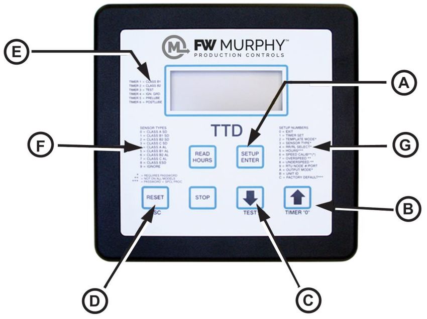
2018-10-22 - 21 -Configuration / Setup of the TTD Annunciator Navigating the TTD Front Panel The TTD Annunciator can be set up by using the Front Panel. The Setup Mode can be entered from either RUN or SHUTDOWN. However, settings can only be changed when the SETUP icon is blinking. (A) [SETUP or ENTER] key (B) [UP ARROW] key (C) [DOWN ARROW] key (D) [ESC] escape key (E) Timer information (F) Sensor types (G) Setup numbers Section 50 00-02-0697 2018-10-22 - 22 -
Entering Setup Mode

                              To enter the Setup Mode, press the [SETUP/ENTER] key and
                              hold until the display shows HOLD. Continue to press the
                              [SETUP/ENTER] key until the model number is displayed.

                              The HOLD display counts down for 6 seconds, shows the model
                              number for 3 seconds and then shows SETUP 0 to indicate the unit
                              is in Setup Mode.
                              Press the [UP ARROW] or [DOWN ARROW] key to move through
                              the Setup values.
                              After selecting a different Setup to view, press the [SETUP/ENTER]
                              key to display the current configuration of that set up value.
                              To change a setting, press [SETUP/ENTER] again to access the
                              menu choices.
                              Enter changes by using the [UP ARROW] or [DOWN ARROW] key.
                              The only time a new value can be entered is when the Setup icon is
                              blinking.

                              Press the [SETUP/ENTER] key again to save the new value. The
                              display will show SAVE for a few seconds and then return to the
                              Setup menu.

                              To exit without saving the change, press [ESC]. Press [ESC] again to
                              exit from the Setup Mode completely. The display will show ESC and
                              then return to the operational screen.

Access During Run and Shutdown
Setup menus and settings can be viewed during RUN or SHUTDOWN, but most menus
cannot be changed while in Run Mode. To assure changes can be made, access Setup menus
while in Shutdown Mode. Press and hold the [SETUP/ENTER] key for 6 seconds to enter the
Setup Mode. The display shows HOLD while the seconds count down.

When the countdown completes, the TTD annunciator is in Setup Mode. The unit model
message displays for about 3 seconds before the SETUP 0 message shows. At this point, use
the [UP ARROW] key to increment to another Setup Mode.

Section 50                                                                               00-02-0697
2018-10-22                                   - 23 -
Password Protected Settings
Some settings are password protected. If a password is
required to change a setting, CODE 00 displays
indicating a numeric password should be entered (M). If
an incorrect password is entered, ERROR (N) displays
for a few seconds, and then the CODE 00 (M) notation
returns to the display.
The password will only need to be entered once during
any editing session. The password is reset when the
editing session is exited or is timed-out due to keypad
inactivity. Entering a code 0, allows read-only access to
Setup menus.
Use the [UP ARROW] and/or [DOWN ARROW] keys to
enter the numeric password specific to that TTD
annunciator.
Inactivity Time Out
Set up procedures need to be started and completed in
a timely manner.
If the TTD annunciator is in any Setup Mode, the display
function returns to the previous level of entry if there are
no key presses within 30 seconds. For example, the
TTD annunciator is in SETUP 3 (O), channel 25 is
selected and the choice of Sensor Type is displayed (P).
After 30 seconds of keypad inactivity, the TTD returns to
SETUP 3 (Q).
If another 30 seconds pass with no keypad activity,
escape is activated, and the unit returns to the
operational screens.
Section 50 00-02-0697
2018-10-22 - 24 -Setup 1 – Timer Setup
This manual explains Setup values in order starting with
SETUP 1. However, once the SETUP icon is blinking,
the [UP ARROW] or [DOWN ARROW] keys can be used
to increment to any Setup option. Once the option is
reached, press the [SETUP/ENTER] key to access the
adjustments for that Setup.
All timers are configured in SETUP 1. (R) When the
SETUP icon is blinking, press the [SETUP/ENTER] key
to reach the specific timer to be set. (Setup icon should
blink about once a second.)
Use the [UP ARROW] or [DOWN ARROW] keys to
change the configuration. Once the change is
completed, press the [ENTER] key to save the changes.
The unit will display SAVE (S) for few seconds, and then
move to the next timer.
If a change is made and the [ESC] key is pressed, the TTD moves to the next timer without
accepting the change. If no changes were made to the setting, press the [ESC] key to return to
SETUP 1, or press [ENTER] to move to the next timer.
Continue to press [ENTER] to move through all timers and review values or make changes to
values as necessary.
Timer 7 Delay Before No-Flow Shutdown
When an internal input detects a No-Flow condition, the
Channel number that detected the condition is displayed
along with Timer 7 and its countdown.
(T) Shows the Timer 7 display during No-flow delay
before shutdown.
(U) Shows Setup 1 – Timer 7 menu.
Timer 7 will not be armed until Timer 1 has expired.
During Timer 1 countdown, the channels enabled as No-
Flow (CH41 - CH44) will be ignored.
Setting Timer 7 to zero (Ø) will cause an immediate
shutdown when Timer 1 has expired, if No-Flow is
detected on any of the four enabled channels.
To enable or disable the No-Flow function use SETUP 4b thru 4E.
Section 50 00-02-0697
2018-10-22 - 25 -The active timer is indicated by the TIMER icon (A), timer number (B) and numeric display (C).
Timer Timer Class Timer Range
Timer 1 Class B1 0 to 5 minutes
Timer 2 Class B2 0 to 10 minutes
Timer 3 Test 0 to 5 minutes
Timer 4 IGN GND 0 to 20 seconds
Timer 5* Pre-lube 0 to 5 minutes
Timer 6* Post-lube 0 to 10 minutes
Timer 7** Delay Before No-Flow Shd. 0 to 10 minutes
* When timer is set to zero (0), the Timer’s feature is disabled or turned off.
** Delay-Only Timer: it does not enable or disable No-Flow functionality.
NOTE: During Run Mode if more than one Timer is active at the same time, the
Timers will be displayed by the TTD in the following priority:
1. Timer 3
2. Timer 1
3. Timer 2
4. Timer 7
Timers not active during the Run Mode will not occur at the same time.
Section 50 00-02-0697
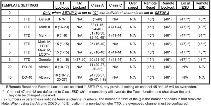
2018-10-22 - 26 -Setup 2 – Sensor Mode
(D) SETUP 2 is a feature that offers choices for
predetermined configurations of sensor class to input
channel. These choices can emulate an existing
annunciator being replaced or configure a new
installation by using the closest template. Units from the
factory are set to an Emulation Template default of 1
with all inputs set to Class A.
Once the unit is in Shutdown Mode, enter SETUP 2 and
choose from one of the eight pre-configured Emulation
Template Settings or chose 0 and configure each
individual sensor channel per your specifications/
requirements. Review the template settings in the first
column of the Emulation Table and enter that number to
select the template. (F)
Emulation Table
Section 50 00-02-0697
2018-10-22 - 27 -After selecting and saving a template, any channel can
be reconfigured by changing a single channel in SETUP
3. To do this, return to SETUP 2 and enter 0 as the
template setting (G). The point on the template
originally selected is not changed with this action. Next,
go to SETUP 3 and change channels, as necessary, to
the preferred configurations.
Terminals 45 & 46 are enabled in SETUP 4 for Remote
Reset and Remote Lockout functionality. If they are not
enabled, they can be configured the same as the other
channel. If they are enabled, they will override any
previous setting. Remote Reset can only be used in
terminal 45, and Remote Lockout can only be used in
terminal 46.
Terminals 47 and 48 are defaulted to Class ESD. This
means they will override the Test function and
Shutdown the unit. The functionality on these channels
can be changed, if desired.
When Template 20 is selected (H), the channel
assignments will duplicate the DD20. Remaining channels are configured as inactive but can
be modified in SETUP 3 once SETUP 2 is set to 0. This also applies to Template 40; with the
exception of channels 50 to 57 that are assigned to TTD terminals 1 to 8.
If Template 20 or Template 40 is used in a unit without the tachometer option, the overspeed
channel must be configured.
Section 50 00-02-0697
2018-10-22 - 28 -TTD Terminal Block Configuration NO/NC for DD-20 TTD Terminal Block Configuration NO/NC for DD-40 Section 50 00-02-0697 2018-10-22 - 29 -
Setup 3 – Sensor Type

Unit must be in Shutdown Mode to edit.

Individual sensor channel can be changed in SETUP 3 (A). As shown in the Sensor Types
table, any channel can be set to one of the 11 available configurations. SETUP 2 must be set
to 0 to make any changes in SETUP 3.

                                         1. Press [SETUP/ENTER].

                                         2. Use the [UP ARROW] key to increment and
                                            change the Channel number.

                                         3. Press [SETUP/ENTER].

                                         4. Use the [UP ARROW] key to select the Type (B).

                                         5. Press [SETUP/ENTER] to SAVE the changes.

Section 50                                                                      00-02-0697
2018-10-22                                  - 30 -
Sensor Types 0 Class A 1 Class B1 2 Class B2 3 Class C 4 Class A Alarm 5 Class B1 Alarm 6 Class B2 Alarm 7 Class C Alarm 8 ESD 9 Ignore (Disabled) 10 Special Lockout* 11 Remote Reset** 12 Remote Lockout** 13 No-flow** * Special Lockout is a fixed 5-minute timer. This timer starts at the same time as the B1 and B2 timers. While timing, the channel assigned this type is locked out. Unlike the B1 and B2 timers, this timer cannot be reset or zeroed while the unit is running. The timer is reset only after shutdown or normal stop. Up to 48 dry contact sensor inputs or FW Murphy device transistor outputs can be connected to the TTD via a terminal block with 48 pair, screw type, each with a jumper for N.O. (Normally Open) or N.C. (Normally Closed) configuration. ** Settings represented as numbers for placeholders only. These values can only be set through other menu options in the TTD. Section 50 00-02-0697 2018-10-22 - 31 -
Setup 4 – Remote Reset Remote Lockout Select and No-Flow Enable Delay

                                       Press the [ENTER] key to read SETUP 4A. Press a
                                       second time to read SETUP 4B.

                                       (D) Use SETUP 4A to set the Remote Reset/Remote
                                       Lockout configuration of preselected channels 45 and
                                       46.

                                       (E) Remote Reset and Lockout are enabled by this
                                       setup and will override any template setting. When the
                                       Remote Reset feature is enabled, a closed contact on
                                       channel 45 resets the TTD annunciator in the same
                                       manner as when using the [RESET] key.

                                       Limit close duration to 1 second. On models with lube
                                       option, Remote Reset will start the Prelube timer.

The Remote Lockout feature resets and inhibits the Class B1, B2 and C timers and fault
inputs. Any faults configured as B1, B2 or C are ignored when channel 46 is an open contact.
When the contact is closed, the timers will be allowed to time and arm the faults. This feature
is intended to be used with automatic start/stop signals, typically connected to a run
confirmation signal to enable the faults after running. Upon an auto-stop, the Remote Lockout
should be re-activated by opening the channel 46 contact, until the next start auto-start signal.

With the unit running and an open contact on channel 46, the display will flash and display the
B1 timer. On units with Tachometer, the display will flash and alternate between RPM reading
and B1 timer.

Configuration Settings
  0    Disabled
  1    Remote Reset assigned in the CH45 (fixed)
  2    Remote Lockout assigned in the CH46 (fixed)
       Remote Reset assigned in the CH45 (fixed) and Remote Lockout assigned in the
 *3
       CH46 (fixed)
* If Remote Reset and Lockout are used simultaneously on models with Lube option, Prelube
timer is only activated if the unit is faulted or in Manual Stop and receives the Remote Reset
signal. The Remote Lockout signal only inhibits the Class B1 and B2 timers. Therefore Prelube
timer is skipped if the system is already reset when the Remote Lockout is released.

Section 50                                                                           00-02-0697
2018-10-22                                    - 32 -
No-Flow Switch Transition Time
Use SETUP 4b through 4E to set No-Flow switch transition times.
Digital input channels 41 to 44 can be configured for detecting a transition of the switches on a
divider block of a compressor system. The channels are scanned to determine if a transition
has occurred in an acceptable time. The time range settings are from 0 to 59 seconds. (The
default setting is zero.)
(G) SETUP 4b is the No-flow screen for CH41
(H) SETUP 4C is the No-flow screen for CH42
(I) SETUP 4d is the No-flow screen for CH43
(J) SETUP 4E is the No-flow screen for CH44
Setting the value to 0 (zero) on any channel will disable
the No-flow function for that channel and allows
SENSOR MODE (SETUP 2) or SENSOR TYPE
(SETUP 3) to determine the Sensor channel
functionality.
A non-zero value enables No-flow function for that
channel and defines the timeout for the channel.
Enabling No-flow function overwrites the channel
SENSOR TYPE or SENSOR MODE configuration
(reserves the channel only for No-flow use).
The Test Mode will be ignored if the No-flow is enabled
for the channel.
Because these inputs are always in transition, the
channels are always tested for open and close.
NOTE: Use SETUP 1 to configure (TMR7) Timer
7 delay before No-Flow shutdown.
Section 50 00-02-0697
2018-10-22 - 33 -Setup 5 - Hourmeters
(K) This setup is for reading and/or resetting the
hourmeter. There are two separate hourmeters:
Hourmeter 5A can be reset.
Hourmeter 5b is the TTD internal hourmeter and
keeps track of total RUN HOURS.
(L) 5A Hourmeter Setting. Range 0 to 99999 hrs. (This
hourmeter can be reset.)
(M) 5b Product Life Timer. Range 0 to 99999 hrs. (11.41
years non-stop. This hourmeter cannot be reset.) The
Product Life Timer reading can also be accessed
through the Modbus or via the Setup menu.
NOTE: The hourmeter registers are in the display head not in the power supply
and are not reset by changing the power supply.
Section 50 00-02-0697
2018-10-22 - 34 -Setup 6 – Speed Calibration
The optional Tachometer functionality is configured in
SETUP 6 (N).
Pulses per Revolution is calibrated as follows:
Press [SETUP/ENTER] to reach SETUP 6A (O).
Pressing [SETUP/ENTER] a second time
increments the display to 6b.
SETUP 6A is the Pulses per Revolution Setting. Speed
input can be either Magnetic pickup (MPU) or CD Ignition
Primary Signal (IGN). The range is .5 to 450. Use the
[UP ARROW] or [DOWN ARROW] keys to reach the
desired setting. Use Settings .5-16.5 with ignition input
for speed, and settings 17-450 for magnetic pickup input (10 kHz max frequency input).
In the Conversion Table, the number of cylinders and cycles of the engine determine the
number of pulses per revolution for ignition input. Divide the number of cylinders by 2 for split
capacitor ignitions. Multiply the number of cylinders by 2 for throwaway spark ignitions.
Conversion Table
Cylinders Cycles Pulses
1 2 1
2 2 2
2 4 1
3 2 3
4 2 4
4 4 2
5 2 5
6 2 6
6 4 3
8 2 8
8 4 4
10 4 5
12 4 6
16 4 8
Section 50 00-02-0697
2018-10-22 - 35 -SETUP 6b (Q) is the RPM Filter Enable and Loss of
Ignition selection and setting. Use the [UP ARROW] or
[DOWN ARROW] keys to select a value. Choose a
setting from the Loss of Ignition Shutdown and RPM
Filter Table to choose a monitoring combination.
Loss of Ignition
Value RPM Filter
Shutdown
0 (default) Enabled Disabled
1 Disabled Disabled
2* Enabled Enabled
3* Disabled Enabled
* If the TTD unit does not have the Tachometer option, only the 0 and 1 values are available.
Loss of Ignition Shutdown is a Class C function that can be armed only after the B1 Timer
(TMR1) expires. When enabled and B1 Timer has expired, CD Ignition must be present (above
90VDC) for at least 15 seconds to arm the Loss of Ignition function. After being armed if CD
Ignition falls below 90VDC for at least 15 seconds, the Shutdown sequence will begin, and
code 49 will be displayed. (See Fault Code table on page 19.)
NOTE: The tolerance of the CD Ignition voltage detection is ±10%. The arming
and shutdown delay of 15 seconds is not adjustable.
RPM filter allows for a DEBOUNCE time before a loss of ignition, underspeed or overspeed
shutdown occurs. The filter (when enabled) will take 3 more RPM readings (typically 500mS)
once the threshold for shutdown has been achieved. If after these 3 attempts, the shutdown is
still valid, a shutdown will occur. If the RPM reading has re-established at a valid state, the unit
will remain running.
Section 50 00-02-0697
2018-10-22 - 36 -Setup 7 – Tachometer Overspeed Option
Fault Code 50. (See Fault Code table on page 19.)
(A) Use SETUP 7 to adjust the Overspeed Setting. The
range is 0 to 5000 RPM.
(B) Press [ENTER] to view the Overspeed setting.
To change the setting, use the [UP ARROW] or [DOWN
ARROW] keys to reach the new Overspeed setting and
press [ENTER] to save the change.
NOTE: Overspeed is a Class A Type Shutdown and is not locked out or
testable during Test Mode.
NOTE: For TTD-T models used with EICS G-Lead/U-Lead for tachometer
readings, disable TTD overspeed and underspeed faults, or false
shutdowns may occur caused by diagnostic signals sent by EICS on the
G-Lead/U-Lead.
Section 50 00-02-0697
2018-10-22 - 37 -Setup 8 – Tachometer Underspeed Option
Fault Code 51. (See Fault Code table on page 19.)
(C) Use SETUP 8 to adjust the Underspeed Setting. The
range is 0 to 5000 RPM.
(D) Press [ENTER] to view the Underspeed setting.
To change the setting, use the [UP ARROW] or [DOWN
ARROW] keys to reach the new Underspeed setting and
press [ENTER] to save the change.
NOTE: Underspeed is locked out by the B1 Timer (Timer 1). Underspeed
will not cause a fault until the B1 timer expires.
NOTE: For TTD-T models used with EICS G-Lead/U-Lead for tachometer
readings, disable TTD overspeed and underspeed faults, or false
shutdowns may occur caused by diagnostic signals sent by EICS on the
G-Lead/U-Lead.
Section 50 00-02-0697
2018-10-22 - 38 -Setup 9 – Communication Settings
(E) Use SETUP 9 to select ports, characteristics and
communication values for remote devices. Use the [UP
ARROW] and/or [DOWN ARROW] to reach setting.
(F) This is the RTU (Remote Terminal Unit) setting. The
range is 1 to 99 (Node number).
(G) This is the Port selection. There are two choices:
0 – RS485
1 – RS232
(H) This is the Baud rate selection. There are five
choices:
0 - 9600,N,8,1
1 - 9600,N,8,2
2 - 19200,N,8,1
3 - 19200,N,8,2
4 - 38400,N,8,1 (only if the pulses/rev setting is greater than 16.5)
5 - 38400,N,8,2 (only if the pulses/rev setting is greater than 16.5)
Section 50 00-02-0697
2018-10-22 - 39 -Setup A – Output Mode
Upon Shutdown, the FV- (Fuel Valve minus) and the
RLY (Relay) terminals change state and either conduct
to ground or open to ground. The change of state
depends on the configuration of SETUP A.
There are four choices (terminals are shown in shut-down state):
Shutdown Mode
Output IGN
Mode Kill RELAY FV- ALR AUX
Closed - alarm event
0 Closed Closed Closed Open
Open - no event
Closed - alarm event
1 Open* Open Open Open
Open - no event
Closed - alarm event
2 Closed Closed Open Open
Open - no event
Closed - alarm event
3 Open* Open Closed Open
Open - no event
Table Note: Closed indicates a closed-to-ground state and open indicates
an open-to-ground state when the TTD unit is in Shutdown Mode.
Open* -- These outputs do not change state during a run mode — they
remain open. Typically used with IGN as a speed input only and the
application does not require grounding ignition on a unit fault.
Use the [UP ARROW] or [DOWN ARROW] key to
select the Output Mode setting. Press [ENTER] to save
the setting.
Section 50 00-02-0697
2018-10-22 - 40 -Setup B – Unit Identification (ID)
(L) This function enables the operator to assign a six-
digit number.
Use the [UP ARROW] arrow key to increment to the
SETUP B option.
(M) Press [SETUP/ENTER] to access the Prefix screen
and the [UP ARROW] or [DOWN ARROW] keys to set
the Prefix ID. The Range is 0 to 99.
Press [ENTER] to save the selection and the (N) Suffix
ID screen displays. Use the [UP ARROW] or [DOWN
ARROW] keys to set the Suffix ID. The range is 0 to
9999.
Section 50 00-02-0697
2018-10-22 - 41 -Setup C – Factory Default
(A) This option returns all settings except the Product
Life Time register back to the default Factory settings.
Use these instructions to return the TTD unit to the
original factory defaults:
1. Enter the correct numeric password. (B)
2. Use the [UP ARROW] key to set the value to 1 (C).
3. Press the [SETUP/ENTER] key to save the change.
The screen display returns to SETUP C.
4. Press the [DOWN ARROW] to reach SETUP 0.
5. Press [ENTER]
6. The EEPR screen displays to verify the factory
defaults have been reinstated. (D)
CAUTION: Executing SETUP C resets all settings,
registers and hours. Shut-down and alarm histories
will also be erased.
Section 50 00-02-0697
2018-10-22 - 42 -Voltage Readings
(E) The internal backup battery, external DC and
ignition voltage readings are available in the VOLT
menu after SETUP C. These readings are updated
approximately every 4 seconds and are read-only.
Press the [ENTER] key to view each of the readings:
- Internal Backup Battery voltage (F)
Press the [ENTER] key to set the Internal Backup
Battery Low Voltage Alarm. Press the up/down arrow
keys to enable (1), to disable return to 0. Press
[ENTER].
- External DC (G)
Press the [ENTER] key to set the External DC
Low Voltage Alarm. Press the up/down arrow
keys to the desired voltage. Press [ENTER].
- Ignition Voltage peak (H)
If the ignition is wired to the TTD unit.
If Internal Backup Battery, External DC and CD Ignition
are connected and operational, power for the TTD
Annunciator has the following priority:
1. External DC is used unless voltage falls below
9VDC.
2. CD Ignition is used unless peak voltage falls
below 90VDC.
3. Internal Backup Battery is used when no other
voltage is present.
NOTE: The TTD Annunciator will operate normally under Internal Backup Battery
power except communication functions and backlight will be disabled.
If Underspeed and/or Loss of Ignition are enabled, the TTD may shut down when
CD Ignition is not present. The tolerance for CD Ignition detection is ±10%.
Section 50 00-02-0697
2018-10-22 - 43 -Software Version
The Version menu (I) offers a quick and easy way to
check the firmware versions in the TTD components.
To verify the current firmware, press [ENTER] to access
the Version SETUP H or SETUP P. Press [ENTER] the
first time to view SETUP H. Pressing [ENTER] a second
time reaches SETUP P.
SETUP H indicates the software version in the Display
Head. In this sample (J), the version is 8.0. (Read 8
point 0)
SETUP P indicates the software version in the Power
Supply. In this sample (K), the version is 8.2. (Read 8
point 2)
Section 50 00-02-0697
2018-10-22 - 44 -Communications Communications Port A single bi-color (GREEN/RED) LED will be provided to give visual indication of active transmit and receive traffic. Interface: Factory configured for RS485; field-selectable for RS232 or RS485 Baud/Configuration: 9600, 19.2K, 38.4K (*); N,8,1;N,8,2 half-duplex communication (set-up configuration is in SETUP 9) Protocol: Modbus RTU Slave (*) (*) The TTD responds to Modbus RTU Read Holding Registers request (Function Code 03). Reads can be up to 50 registers per request. An attempt to read over 50 will return an exception code. When the TTD is on the same RS485 network with other devices, a minimum 125mS poll delay must be used between each device on the network or time outs will occur from the TTD. The Modbus RTU master should be configured to use retries on the TTD, and typical timeout setting for the TTD should be 500mS or greater. Connection: There will be 2 screw terminals provided for RS485. These will be printed or labeled as A and B. A is the non-inverting (+) signal. B is the inverting (-) signal. There will be 3 screw terminals provided for RS232. These will be printed or labeled as RX, TX and GND. RX is the receive signal, TX is the transmit signal and GND is the signal ground reference. (*) 38.4K Baud will not be available when IGN input is selected as the source for RPM calculations. When MPU is selected, this feature is available for selection. Section 50 00-02-0697 2018-10-22 - 45 -
Modbus Register Address Listings
Address       Description                                             Type      Min Value       Max. Value         Default Value
40,001        RPM                                                       R           -                -                    -
40,002        ETM (Elapsed Time Meter 0-65535 Hrs.) (*)                 R           -                -                    -
40,003        Class B1 Timer (secs.)                                    R           -                -                    -
40,004        Shutdown Code                                             R           -                -                    -
              Output Status Bit Map
              Bit 0 – Ignition (1 ground, 0 ungrounded)
              Bit 1 – Fuel Valve (1 ground, 0 ungrounded)
40,005                                                                  R             -                -                    -
              Bit 2 – Alarm (1 ground, 0 ungrounded)
              Bit 3 – Pre/Post Lube (1 ground, 0 ungrounded)
              Bits 4, 5, 6 and 7 – N/A
40,006        Inputs 1-16 Status Bit Map                                R             -                 -                  -
40,007        Inputs 17-32 Status Bit Map                               R             -                 -                  -
40,008        Inputs 33-48 Status Bit Map R                             R             -                 -                  -
40,009        Class B2 Timer (secs.)                                    R             -                 -                  -
40,010        Test Timer (secs.)                                        R             -                 -                  -
40,011        Ignition Ground Timer (secs.)                             R             -                 -                  -
40,012        PreLube Timer (secs.)                                     R             -                 -                  -
40,013        PostLube Timer (secs.)                                    R             -                 -                  -
40,014        No-Flow Timer (secs.)                                     R             -                 -                  -
40,015        TTD-H SPI (diagnostic use only)                           R             -                 -                  -
40,016        PS-TTDH Sync. Flag                                        R             -                 -                  -
40,017        TTD-P SPI (diagnostic use only)                           R             -                 -                  -
40,018        Battery Voltage x10                                       R             -                 -                  -
40,019        External DC Voltage x10                                   R             -                 -                  -
40,020        Ignition Voltage x10                                      R             -                 -                  -
40,021        B1 Timer Setting (TMR1)                                 R/W**           0               300                 300
40,022        B2 Timer Setting (TMR2)                                 R/W**           0               599                 599
40,023        Ignition Timer Setting (TMR4)                           R/W**           0                20                  3
40,024        PreLube Timer Setting (TMR5)                            R/W**           0               300                 300
40,025        PostLube Timer Setting (TMR6)                           R/W**           0               599                 599
40,026        Sensor Mode Setting                                     R/W*            0                40                  1
40,027        Input Type #01                                          R/W*            0                10                  0
40,028        Input Type #02                                          R/W*            0                10                  0
40,029        Input Type #03                                          R/W*            0                10                  0
40,030        Input Type #04                                          R/W*            0                10                  0
40,031        Input Type #05                                          R/W*            0                10                  0
40,032        Input Type #06                                          R/W*            0                10                  0
40,033        Input Type #07                                          R/W*            0                10                  0
40,034        Input Type #08                                          R/W*            0                10                  0
(*) Hours greater than 65535 will rollover to 0. This is a 16-bit limit of the register; however, the TTD supports up to 99,999 hours.
* Only accept Modbus write register(s) during Shutdown Mode.
** Accept Modbus write register(s) during Run and Shutdown Modes.

Section 50                                                                                                                      00-02-0697
2018-10-22                                                            - 46 -
Modbus Register Address Listings (continued) Address Description Type Min Value Max. Value Default Value 40,035 Input Type #09 R/W* 0 10 0 40,036 Input Type #10 R/W* 0 10 0 40,037 Input Type #11 R/W* 0 10 0 40,038 Input Type #12 R/W* 0 10 0 40,039 Input Type #13 R/W* 0 10 0 40,040 Input Type #14 R/W* 0 10 0 40,041 Input Type #15 R/W* 0 10 0 40,042 Input Type #16 R/W* 0 10 0 40,043 Input Type #17 R/W* 0 10 0 40,044 Input Type #18 R/W* 0 10 0 40,045 Input Type #19 R/W* 0 10 0 40,046 Input Type #20 R/W* 0 10 0 40,047 Input Type #21 R/W* 0 10 0 40,048 Input Type #22 R/W* 0 10 0 40,049 Input Type #23 R/W* 0 10 0 40,050 Input Type #24 R/W* 0 10 0 40,051 Input Type #25 R/W* 0 10 0 40,052 Input Type #26 R/W* 0 10 0 40,053 Input Type #27 R/W* 0 10 0 40,054 Input Type #28 R/W* 0 10 0 40,055 Input Type #29 R/W* 0 10 0 40,056 Input Type #30 R/W* 0 10 0 40,057 Input Type #31 R/W* 0 10 0 40,058 Input Type #32 R/W* 0 10 0 40,059 Input Type #33 R/W* 0 10 0 40,060 Input Type #34 R/W* 0 10 0 40,061 Input Type #35 R/W* 0 10 0 40,062 Input Type #36 R/W* 0 10 0 40,063 Input Type #37 R/W* 0 10 0 40,064 Input Type #38 R/W* 0 10 0 40,065 Input Type #39 R/W* 0 10 0 40,066 Input Type #40 R/W* 0 10 0 40,067 Input Type #41 R/W* 0 10 0 40,068 Input Type #42 R/W* 0 10 0 40,069 Input Type #43 R/W* 0 10 0 40,070 Input Type #44 R/W* 0 10 0 40,071 Input Type #45 R/W* 0 10 0 40,072 Input Type #46 R/W* 0 10 0 40,073 Input Type #47 R/W* 0 10 0 40,074 Input Type #48 R/W* 0 10 0 40,075 Remote Reset / Remote Lockout Setting R/W* 0 3 0 40,076 Hours Setting R/W* 0 65535(*) 0 40,077 Pulses Per Revolution Setting x10 R/W* 5 4500 60 40,078 RPM Filter/Loss of Ignition Setting R/W* 0 3*** 0 40,079 Overspeed Setting R/W** 0 5000 1000 40,080 Underspeed Setting R/W** 0 5000 100 40,081 Output Mode Setting R/W* 0 3 0 40,082 ID- Prefix R/W** 0 99 0 40,083 ID- Sufix R/W** 0 9999 0 40,084 Password R/W** 0 99 - (*) Hours greater than 65535 will rollover to 0. This is a 16-bit limit of the register; however, the TTD supports up to 99,999 hours. * Only accept Modbus write register(s) during Shutdown Mode. ** Accept Modbus write register(s) during Run and Shutdown Modes. *** Range is 0 to 1 for non-Tachometer models. (See SETUP 6 - SPEED CALIBRATION section for details). Section 50 00-02-0697 2018-10-22 - 47 -
Modbus Register Address Listings (continued)
Address      Description                                       Type     Min Value     Max. Value        Default Value
40,085       Test Timer Setting (TMR3)                         R/W**        -0           300                 300
40,086       Life Timer                                          R           -             -                   -
40,087       TTD-H Firmware x10                                  R           -             -                   -
40,088       PSU-X Firmware x10                                  R           -             -                   -
             PSU Type
             120 - Base Model + No Flow
             121 - Base Model + Tach + No Flow
             122 - Base Model + Lube + No Flow
40,089       123 - Base Model + Tach + Lube + No Flow            R           -               -                 -
             124 - Base Model
             125 - Base Model + Tach
             126 - Base Model + Lube
             127 - Base Model + Tach + Lube
40,090       OSC Calibration                                     R           -               -                -
40,091       PSU Power-up (PUR or WDT)                           R           -               -                -
40,092       PSU Update History Shutdown Data                    R           -               -                -
40,093       No-Flow Timer Setting (TMR7)                      R/W**         0             599                0
40,094       CH41 TON/TOFF                                     R/W*          0              59                0
40,095       CH42 TON/TOFF                                     R/W*          0              59                0
40,096       CH43 TON/TOFF                                     R/W*          0              59                0
40,097       CH44 TON/TOFF                                     R/W*          0              59                0
40,098       Low DC Voltage Alarm                              R/W**         0              32                0
40,099       Low Backup Battery Alarm                          R/W**         0              1                 0
40,100       N/A                                                 R           -               -                -
40,101       SD History #1                                       R           -               -                0
40,102       ETM @ SD1                                           R           -               -                0
40,103       SD History #2                                       R           -               -                0
40,104       ETM @ SD2                                           R           -               -                0
40,105       SD History #3                                       R           -               -                0
40,106       ETM @ SD3                                           R           -               -                0
40,107       SD History #4                                       R           -               -                0
40,108       ETM @ SD4                                           R           -               -                0
40,109       SD History #5                                       R           -               -                0
40,110       ETM @ SD5                                           R           -               -                0
40,111       SD History #6                                       R           -               -                0
40,112       ETM @ SD6                                           R           -               -                0
40,113       SD History #7                                       R           -               -                0
40,114       ETM @ SD7                                           R           -               -                0
40,115       SD History #8                                       R           -               -                0
40,116       ETM @ SD8                                           R           -               -                0
40,117       SD History #9                                       R           -               -                0
40,118       ETM @ SD9                                           R           -               -                0
40,119       SD History #10                                      R           -               -                0
40,120       ETM @ SD10                                          R           -               -                0
40,121       Alarm History #1                                    R           -               -                0
40,122       ETM @ AL1                                           R           -               -                0
40,123       Alarm History #2                                    R           -               -                0
40,124       ETM @ AL2                                           R           -               -                0
40,125       Alarm History #3                                    R           -               -                0
40,126       ETM @ AL3                                           R           -               -                0
40,127       Alarm History #4                                    R           -               -                0
40,128       ETM @ AL4                                           R           -               -                0
* Only accept Modbus write register(s) during Shutdown Mode.
** Accept Modbus write register(s) during Run and Shutdown Modes.
*** Range is 0 to 1 for non-Tachometer models. (See SETUP 6 - SPEED CALIBRATION section for details).

Section 50                                                                                                         00-02-0697
2018-10-22                                                     - 48 -
Specifications
Power Requirements
PSU-2: 10-32VDC, 10W (max); 90-400VDC CD Ignition, 750uA @ 100VDC (max)
On-Board Backup Power: Lithium battery, 6 VDC, 1300 mAh
Digital Inputs: 48 (a.k.a. Channels)
Sensor Types: Discrete Input, N.O. / N.C., non-incendive (with use of PSU-2)
Magnetic Pickup Input
One Magnetic Pickup Sensor Input: 3.6 - 120 VAC, 2-10 kHz
Outputs
IGN: 0.4A @ 400VDC (*) for 5 seconds
RLY: 0.5A @ 48VDC cont. duty
0.15A @ 400VDC (*) cont. duty
FV- : 0.5A @ 400VDC (*) cont. duty
ALR: 0.5A @ 48VDC cont. duty
AUX: 0.5A @ 48VDC cont. duty
(*) CSA approval for 250VDC maximum
Operator Interface
Display Type: LCD, Static, 80 segment, custom text with LED Backlight
Display Viewable Area: ~ 2.79 x 1 in. (71.04mm x 25.4mm)
Display Contrast: Automatic
Display Backlight: Yellow (Normal Operation), Red (Shutdown)
(Backlight will only be available when unit is powered by DC or AC.)
Voltage Level Monitor: Monitor and display voltage level of DC Supply, CD Ignition and internal battery
Keypad: 6 switches: Ridge Embossed, Metal Dome, Tactile 14 Oz. Trip Force
Enclosure Cutout: 5.50 x 5.50 inches (133 mm)
Operating Temperature: -40 to +85 degrees C
Viewable Temperature: -40 to +85 degrees C
Storage Temperature: -40 to +85 degrees C
Tachometer Accuracy: ±0.5% of the display reading or ±1 RPM, whichever is greater
Resetable Hourmeter Range: 0 to 99999 hrs.
Non-Resetable Hourmeter Range: 0 to 99999 hrs.
Hourmeter Accuracy: ±1 hour per year
Section 50 00-02-0697
2018-10-22 - 49 -Specifications (continued) Communication Port A single bi-color (GREEN/RED) LED is provided to give visual indication of active transmit and receive traffic Interface: Factory configured for RS485; field-selectable for RS232 or RS485 Baud/Configuration: 9600, 19.2K, 38.4K (**); N, 8, 1; N, 8, 2 half-duplex communication Protocol: Modbus RTU slave Connection: There will be 2 screw terminals provided for RS485 There will be 2 screw terminals provided for RS232 There will be 1 screw terminal common for both ports labeled as GND (**) 38.4K baud will not be available when IGN input is selected as the source for RPM calculations. When MPU is selected, this feature is available for selection Third Party Approvals TTD-H, PSU-2: CSA Class I, Division 2, Groups B, C, and D TTD-H: IEC 60529 – IP66 (NEMA 4 and 4X equivalent) Intuitive Display Icons Display status and assist in setup and operation resulting in greater ease of operation and interface. The appropriate icon will turn on to indicate unit status or navigation through the set-up features. RUN - Run mode RPM – Screen Value HOURS – Screen Value TYPE – Channel Type Configuration LOW BATT – Low Battery Warning (displayed only when condition exists) HISTORY – Shutdown History TEST – Test Mode LUBE – Pre-lubrication Timer POSTLUBE – Post-lubrication Timer SHUTDOWN – Stop Mode ALARM – Alarm(s) Warning (displayed only when condition exists) SETPOINT – Edit Set-point Value SETUP – Setup Menu(s) Section 50 00-02-0697 2018-10-22 - 50 -
You can also read