ThermoVision Micron/A10 Camera User's Guide - 412-0006-10 Version 130 - FLIR Systems
←
→
Page content transcription
If your browser does not render page correctly, please read the page content below
ThermoVision® Micron/A10 User’s Guide 412-0006-10 Version 130

ThermoVision®
Micron/A10 Camera
User’s Guide
412-0006-10
Version 130

                                FLIR Systems
                                Indigo Operations
                                   70 Castilian Dr.
                               Goleta, CA 93117-3027
                           805 964-9797 FAX 805 685-2711
                               www.indigosystems.com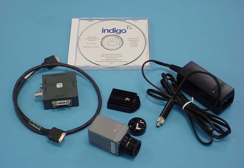
ThermoVision® Micron/A10 User’s Guide 412-0006-10 Version 130

TABLE OF CONTENTS
1      INTRODUCTION................................................................................................................. 4

2      MICRON/A10 SPECIFICATIONS .................................................................................... 4

3      OPTIONAL MICRON/A10 FEATURES........................................................................... 5

4      UNPACKING YOUR MICRON/A10 CAMERA .............................................................. 6

5      OPTIONAL MICRON/A10 ACCESSORIES.................................................................... 7

6      OVERVIEW OF THE MICRON/A10 ELECTRICAL INTERFACE............................ 8
    INPUT POWER............................................................................................................................... 8
    ANALOG VIDEO OUTPUT ............................................................................................................. 9
    COMMAND AND CONTROL CHANNEL ........................................................................................... 9
    DIGITAL DATA CHANNEL ............................................................................................................ 9
BASIC OPERATION OF THE MICRON/A10 CAMERA .................................................... 10

7      REMOTE CONTROL OF THE MICRON/A10 CAMERA .......................................... 14
    INSTALLATION OF MICRON/A10 CONTROL PANEL SOFTWARE .................................................. 14
    CONNECTING MICRON/A10 TO A PC VIA THE I/O MODULE ....................................................... 15
    CONNECTING MICRON/A10 TO A PC VIA THE ETHERNET MODULE ........................................... 16
    CONNECTING MICRON/A10 TO A PC VIA THE FIREWIRE(IEEE-1394) MODULE ........................ 17
    TROUBLESHOOTING THE COMMAND & CONTROL LINK ............................................................. 19
    OPERATION OF THE MICRON/A10 CONTROL PANEL .................................................................. 20
      7.1.1    Control Panel General Tab .................................................................................. 20
      7.1.2    Control Panel Video Tab ...................................................................................... 23
      7.1.3    Control Panel Digital Tab .................................................................................... 27
      7.1.4    Control Panel Advanced Tab................................................................................ 28
      7.1.5    Control Panel Menu Options ................................................................................ 30
8      MICRON/A10 DIGITAL DATA CHANNEL.................................................................. 33
    USING THE DIGITAL DATA CHANNEL ........................................................................................ 34
9      MICRON/A10 PHYSICAL INTERFACE ....................................................................... 34
    DIMENSIONED DRAWINGS ......................................................................................................... 34
    MOUNTING................................................................................................................................. 34
APPENDIX A: PIN-OUT DEFINITIONS ............................................................................... 39
    CAMERA I/O .............................................................................................................................. 39
    I/O MODULE .............................................................................................................................. 40

                COPYRIGHT NOTICE © INDIGO SYSTEMS CORPORATION 2003

                                                                    2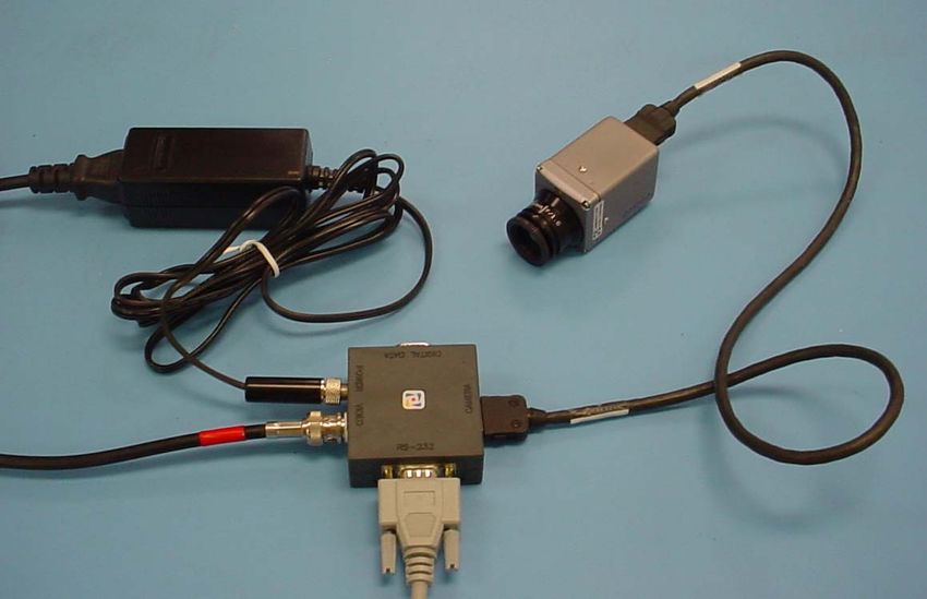
ThermoVision® Micron/A10 User’s Guide 412-0006-10 Version 130

        Cautions:

   •   Do not remove the camera cover. Disassembly of the camera (including removal of the
       cover) can cause permanent damage and will void the warranty.

   •   Operating the camera outside of the specified input voltage range or the specified
       operating temperature range can cause permanent damage.

   •   The camera is not sealed. Avoid exposure to dust and moisture and replace the lens cap
       when not in use.

   •   Do not image extremely high intensity radiation sources, such as the sun, lasers, arc
       welders, etc.

   •   The camera is a precision optical instrument and should not be exposed to excessive
       shock and/or vibration. Refer to the Product Specification (ISC doc. 102-0005-09) for
       detailed environmental requirements.

   •   This camera contains static-sensitive electronics and should be handled appropriately.

   •   If you have questions that are not covered in this manual, or need service, contact
       Customer Support at (805) 964-9797 for additional information prior to returning a
       camera.

                                              3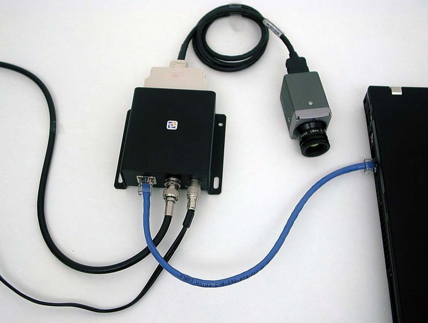
ThermoVision® Micron/A10 User’s Guide 412-0006-10 Version 130
1 INTRODUCTION
The ThermoVision® Micron or ThermoVision® A10 is a long-wavelength (7.5 – 13.5 microns)
uncooled microbolometer camera designed for infrared imaging applications that demand absolute
minimum size, weight, and power consumption. It is available with five different lens options:
8.5mm focal length (55° x 41° field of view), 11mm focal length (40° x 30°), 18 mm (25° x 19°),
30 mm (15° x 11°) or 50 mm (9° x 7°). The camera provides “power-in, video-out” capability,
which means that one need only apply input voltage to receive analog video. However, for
applications demanding more advanced control, Micron/A10 includes a serial interface (RS-232)
and Control Panel software for transmitting camera commands and receiving status.
Micron/A10 also provides an optional digital data interface via parallel, firewire or ethernet
interface.
2 MICRON/A10 SPECIFICATIONS
• 164 (H) x 128 (V) uncooled microbolometer sensor array, 51 x 51 micron pixels
• Input power range: 3.5V – 9.0VDC (7.5V – 30.0V, optional)
• Power Consumption: 1.5 Watts (nominal at room temperature with 8V input)
• Operating Temperature Range: 0°C to 40° C (-40°C to +55°C extended range, optional)
• Humidity: 95% non-condensing
• Dimensions: see detailed drawings in Section 9
• Weight: approx 107 grams for 11 mm, 18 mm & 30 mm; 150 grams for 50 mm
• Analog video output: NTSC (PAL optional)
• Remote interface: RS-232 (Control Panel software included.)
• Included features:
o “Smart Scene” image optimization. (Automatic adjustment of image brightness
and contrast as the scene content changes so that imagery never appears
under/overexposed or “washed out”. See page 20 for more details.)
o Dual exposure states. See page 22 for more details.
Low-temperature state: NEdT < 85 mK, Max. scene range > 150 oC (at 25 oC ambient).
High-temperature state: NEdT < 350 mK, Max. scene range > 500 oC (at 25 oC ambient).
o On-screen symbols, including a low-voltage indicator and overtemp indicator.
See page 26 for more details.
Note: These specifications are subject to change without notice. See the Product Specification
(ISC doc. 102-0005-09) for detailed functional, performance, and environmental requirements.
See the Interface Control Document (ISC doc. 102-0005-03) for detailed interface
descriptions.
4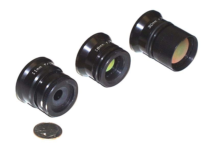
ThermoVision® Micron/A10 User’s Guide 412-0006-10 Version 130

3   OPTIONAL MICRON/A10 FEATURES
    •   Extended input voltage range: 7.5V – 30.0V (standard range is 3.5V – 9.0V)
    •   Extended operating temperature range: -40 oC to +55 oC (standard range 0 oC to +40 oC)
    •   PAL video format (See page 9. Standard video output is NTSC.)
    •   Automatic dynamic range control (i.e. automatic selection of high-temperature and low-
        temperature modes based. See page 22.)
    •   Spot-meter capability (See page 28.)
    •   Includes color isotherm capability (See page 29.)
    •   Includes digital output channel (See page 33.)

    Note: Please contact Customer Support at (805) 964-9797 for information on upgrading your
    camera.

                                                   30 mm

                                   18 mm

                    11 mm

                       Figure 1: Three of the available lens configurations

                                               5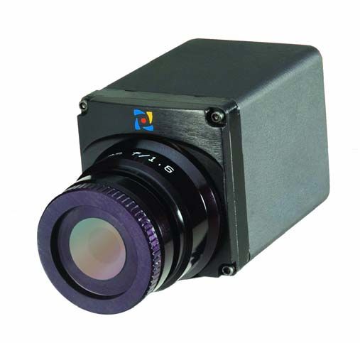
ThermoVision® Micron/A10 User’s Guide 412-0006-10 Version 130

4   UNPACKING YOUR MICRON/A10 CAMERA
The items shown in Figure 2 come standard in your Micron/A10 Camera package. If there is
any discrepancy between this list and the contents of your camera package, please contact Indigo
Systems Customer Support immediately at (805) 964-9797.

    1. Micron/A10 camera
    2. I/O Module
    3. Interface cable (3’ length is standard. See Section 5 for other available lengths.)
    4. 110/220V AC/DC Converter with outlet plug
    5. Tripod adapter
    6. Lens cap
    7. Control Panel software
    8. User’s Guide

                                                        7

                                                        8

                            2                       5
                                                                                4

                                                            6

                                          1

                    3

                           Figure 2: Standard Micron/A10 Equipment

                                               6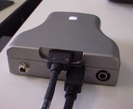
ThermoVision® Micron/A10 User’s Guide 412-0006-10 Version 130

     5    OPTIONAL MICRON/A10 ACCESSORIES
         •   6”, 3’, 10’ or 25’ interface cable
         •   3’, or 10’ Power / Video Cable (replaces Interface Cable and I/O Module)
         •   Digital data serial-to-parallel module (parallel data cable sold separate)
         •   IEEE-1394 Firewire Module (Figure 3a)
         •   iPAQ handheld Remote Control Panel with cable and adapter (Figure 3b)
         •   Ethernet Interface Adapter Module (Figure 3c)
         •   Environmental enclosure (Figure 3d)
         •   Hotshoe adapter* with or without Sony DCR-TRV Camcorder (Figure 3e)
         •   Self-contained rechargeable battery pack (Figure 3f)
         •   Battery / battery charger (not pictured)

                                                                                    (d) Remote Control
                                                                                          Panel

              3a                                      3b
                                                                                             3c

3d                                       3e                                    3f

                                 Figure 3: Some of the Micron/A10 Accessories

     *
      The Hotshoe adapter interfaces the Micron/A10 camera directly to a Sony DCR-TRV Camcorder with an
     Intelligent Accessory Interface (i.e. Hotshoe) and video input. With the Hotshoe adapter, the Micron/A10 camera
     and the camcorder becomes a single integrated system using a common battery, display, and recording mechanism.

                                                           7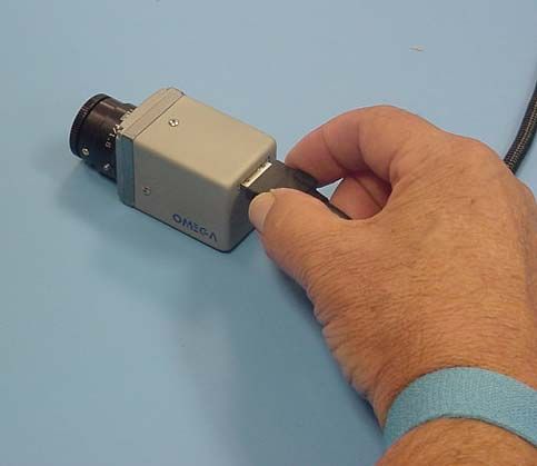
ThermoVision® Micron/A10 User’s Guide 412-0006-10 Version 130

6   OVERVIEW OF THE MICRON/A10 ELECTRICAL INTERFACE
The Micron/A10 camera provides all input/output signals via a single 18-pin connector. The
signals on this connector include input power, analog video output, serial communication
channel for command and control and the digital data output.

Note: See the Interface Control Document (ISC doc. 102-0005-03) for detailed interface
requirements. Pin-out definitions for the camera and the I/O Module are provided in Appendix A.

Input Power
Included with the Micron/A10 camera is an AC/DC converter that generates 8VDC input power
from 110 VAC or 220 VAC. If you prefer to provide your own power supply, please verify that
the input power at the camera connector meets the specifications shown in Table 1.

CAUTION: Reversing polarity of input power will damage the camera’s internal power supply
and repair is not covered under the camera warranty.

       Table 1: Input Power Requirements
         Parameter            Baseline    Value with Optional   Comment
                               Value        Preconditioner
         Minimum voltage       3.5V               7.5V          Voltage at the camera
                                                                connector
         Maximum voltage       9.0V               30.0V         Voltage at the camera
                                                                connector
         Max. Ripple          100 mV             100 mV         Peak-to-peak from DC to
                                                                10 MHz
         Peak Load Power     2500 mW             2500 mW        When actuating the shutter
                                                                mechanism

Note: To use the Firewire Module and a Micron/A10 camera with the Extended Voltage Range
option, the maximum voltage input is 12.0 V to the module.

                                             8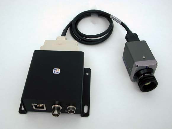
ThermoVision® Micron/A10 User’s Guide 412-0006-10 Version 130

Analog Video Output
The video output of the Micron/A10 camera can be configured to either NTSC or PAL-
compatible.* In either case, the output is intended to drive a 75-ohm load impedance. See Table
2 for a list of other relevant video parameters.

                   Table 2: Video parameters
                     Parameter                             NTSC                   PAL
                     Monochrome equivalent               RS-170A                  CCIR
                     Frame rate                            30 Hz                  25 Hz
                     Active video lines                    480                        512
                     # displayed detector samples    160 (H) x 120 (V)      160 (H) x 128 (V)

Note: To use the Micron/A10 Isotherm option, the video monitor must be color capable. For
display of Micron/A10 video without Isotherm capability, a monitor complying with the
monochrome-equivalent standard shown in Table 2 can be used.

Command and Control Channel
Remote control of the Micron/A10 camera is provided via a RS-232 serial interface. Section 8
provides detailed information regarding this interface.

Digital Data Channel
Micron/A10 provides a digital channel with real-time serialized digital video. The camera
outputs either 8-bit or 14-bit data. Conversion of the digital data to a parallel format for data
acquisition requires a serial-to-parallel converter accessory; or can be provided via a Firewire or
Ethernet Module which are also accessories. Section 9 provides detailed information regarding
this interface.

*
    NTSC is the U.S. standard for color analog video. PAL is the European standard.

                                                       9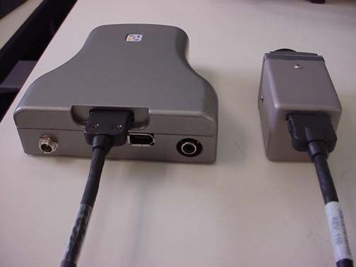
ThermoVision® Micron/A10 User’s Guide 412-0006-10 Version 130

BASIC OPERATION OF THE MICRON/A10 CAMERA
Note: If you are using the Ethernet Module, environmental enclosure, integral battery pack,
Remote Control Panel or Hotshoe adapter additional instructions may also be provided.

   1. If you intend to mount the camera on a tripod, attach the tripod adapter plate to the
       bottom of your Micron/A10 camera using a 5/64 “ hex driver.
   2. Remove the lens cap. (Remember to replace the lens cap when the camera is not in use
       to prevent accidental scratching and dust contamination.)
   3. If using the standard Interface Cable and I/O Module, plug one end of the Interface Cable
       into the mating connector on the back of the camera, as shown in Figure 4. (Either end of
       the Interface Cable can be plugged into the camera.) Connect the other end of the
       Interface Cable to the mating connector on the I/O Module labeled “CAMERA”.
   4. If using the optional Power/Video Cable, plug the 18-pin connector into the mating
       connector on the back of the camera.
   5. If you are using the Ethernet Module, plug one end of the Interface Cable into the mating
       connector on the back of the camera, as shown in Figure 4. Connect the other end of the
       Interface Cable to the mating connector on the Ethernet Module, also shown in Figure 5.
       Connect a standard ethernet cable (CAT-5) between the Ethernet Module and the PC.
   6. If using the optional Firewire Module, plug one end of the Interface Cable into the
       mating connector on the back of the camera, as shown in Figure 6. Connect the other end
       of the Interface Cable to the mating connector on the Firewire Module, also shown in
       Figure 7. For connection with laptops an Indigo 9-Volt power supply must be connected
       to power Firewire Module, as shown in Figure 8.
   7. Attach one end of a standard BNC cable or RCA for the Firewire (either not included) to
       the video port labeled “VIDEO” on the I/O Module, Ethernet, Firewire or on the optional
       Power/Video Cable. Attach the other end to a compatible video monitor.
   8. Plug the AC/DC converter into an electrical outlet. Insert the circular plug at the other
       end of the AC/DC converter into the power jack labeled “POWER” on the I/O Module,
       Ethernet, Firewire or the optional Power/Video Cable. The camera will take ~1 second
       to produce an image after application of power.
   9. The camera will automatically perform a flat-field correction (FFC) at periodic intervals.
       This operation, which improves image quality, takes less than 1/2 second to complete.
       This feature can be disabled or controlled manually or with a time delay via the
       Micron/A10 Control Panel (See page 22.)
   10. If you intend to use the Micron/A10 Control Panel for remote control of the camera,
       follow the additional steps described in Section 7. Figure shows the I/O Module and
       camera after cabling power, analog video, and RS-232, Ethernet or Firewire interface.
   11. If you intend to use the digital data channel, follow the additional steps described in
       Section 8.

                                            10
ThermoVision® Micron/A10 User’s Guide 412-0006-10 Version 130
Figure 4: Connecting the Interface Cable to the Micron/A10
To electrical outlet
To video
monitor
To PC (only required if using RS-232
interface.)
Figure 5: Micron/A10 after cabling
11ThermoVision® Micron/A10 User’s Guide 412-0006-10 Version 130
Figure 6: Micron/A10 and Ethernet Module
Micron/A10
Ethernet
To video monitor interface cable
Laptop with
standard RJ45
connector
Standard CAT-5
LAN cable
To Indigo 9-Volt power supply
Figure 7: Laptop connected to Micron/A10 and Ethernet Module
12ThermoVision® Micron/A10 User’s Guide 412-0006-10 Version 130
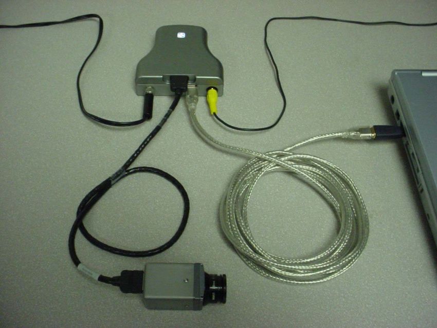
Figure 8: Micron/A10 and Firewire Module
To video monitor
To Indigo 9-Volt power
supply
Laptop with
built-in 4-pin
Firewire port
6-pin to 4-pin
adapter
Figure 9: Laptop connected to Micron/A10 and Firewire Module
13ThermoVision® Micron/A10 User’s Guide 412-0006-10 Version 130
7 REMOTE CONTROL OF THE MICRON/A10 CAMERA
Micron/A10 provides advanced camera control through an RS-232 serial interface. This can be
accessed using a PC with either the standard serial communications port and the I/O Module or
using the Ethernet Module or with the Firewire Module. Included with your Micron/A10 is a
PC-based Control Panel software that communicates with the camera. This software provides
remote control of various camera features and modes as well as image capture using a graphical
user interface (GUI). The Micron/A10 Control Panel software is compatible with Windows
2000 / 2000 Professional, and Windows XP Professional. The PC must have a spare serial
communications port for the I/O Module or a spare LAN/RJ45 connector for the Ethernet
Module or a spare FireWire (IEEE-1394) port for the Firewire Module to execute the Control
Panel software.
Note: If using the optional Firewire Module and your computer does not have a built-in
Firewire port, you can add FireWire to your system. The addition of a FireWire PCI
Host Adapter or using a FireWire PCMCIA Cardbus Card can also be used.
If your application demands a more portable means of camera control, a button-panel accessory
installed on a Compaq iPAQ handheld computer is offered as an option. Operation of the iPAQ
Control Panel is described in separate documentation provided with that accessory. For
Omega™ users with embedded or specialty applications that require custom control software, a
Software Developer’s Kit (SDK) and an Interface Control Document (ICD) are available to
support your development efforts. Those intending to generate their own custom software are
encouraged to read the remainder of this section regarding the Micron/A10 Control Panel to
better understand the camera modes and parameters.
Installation of Micron/A10 Control Panel Software
1. Insert the CD marked Micron/A10 Control Panel Install Disk into your CD-ROM drive.
If the setup program (setup.exe) does not execute automatically, then execute it by
finding setup.exe in the CD-ROM with Windows Explorer and double-clicking the icon.
(Alternatively, you can select “Run” from your Windows start menu, and then type “E:\
setup.exe”, replacing E: with the appropriate drive-letter for your CD-ROM.)
2. The installation program will present instructions for installing the application to your
hard drive. By default, the setup wizard will install the application in the directory
C:\ProgramFiles\Indigo\ThermoVision Micron, and the filename is Micron Control
Panel.exe.
Note: If using the Ethernet Module further steps are required to install. Please refer to the
included install guide ISC doc. 421-0007-12. If using the Firewire Module and a PC running
Windows XP further steps will be required to install the device driver. Please refer to the
included install guide ISC doc. 421-0012-12.
14ThermoVision® Micron/A10 User’s Guide 412-0006-10 Version 130
Connecting Micron/A10 to a PC via the I/O Module
1. Follow the steps shown in Section 0 for basic operation of the Micron/A10 camera. After
verifying that the camera is producing an image, power down the camera.
2. Connect one end of a standard serial cable (not included) to the 9-pin female DB9
connector on the I/O module labeled “RS-232”.
3. Connect the other end of the standard serial cable to an unused serial port on your
computer. These ports are usually labeled “COM1”, “COM2”, etc.
4. Power on the camera. Assuming the Control Panel software is already installed on the
PC (see installation instructions above), execute the software.
5. The Control Panel software will attempt to automatically identify the COM port upon
which the camera is installed. If the Control Panel successfully links to the camera, skip
ahead to the section below titled “Operation of the Micron/A10 Control Panel”.
6. If you see the window shown in Figure 10, verify that the camera is powered on and
connected to the PC. Then select the RS232 option and appropriate COM port then hit
the “Apply” button. If the Control Panel successfully links to the camera, skip ahead the
section below titled “Operation of the Micron/A10 Control Panel”.
Figure 10: Control Panel Select RS232 Comm Window
7. Following Step 6, if you are still having trouble communicating with the camera then
refer to the guidelines in the following section, titled “Troubleshooting the Command &
Control Link”
15ThermoVision® Micron/A10 User’s Guide 412-0006-10 Version 130
Connecting Micron/A10 to a PC via the Ethernet Module
1. Follow the steps shown in Section 0 for basic connection of the Micron/A10 camera and
the Ethernet Module.
2. Connect one end of a CAT5 cable to the RJ45 port on the Ethernet Module, as shown in
Figure 11.
3. Connect the other end of the CAT5 cable to an open RJ45 port on your computer. The
port is usually available on the back of the PC through a standard LAN network interface
card or NIC card. If using computer with only one LAN connection then you may want to
add an additional NIC card in an open PCI slot to be dedicated for the camera; otherwise,
use the existing LAN connection. Contact your IT department for network connection
instructions.
Figure 12: Ethernet connection
4. Assuming the Micron/A10 Control Panel software is already installed on the PC (see
installation instructions above), execute the software.
5. The Micron/A10 Control Panel software will attempt to automatically identify the port
upon which the camera is installed. When the Network Device Finder window pops up,
as shown in Figure 13, right click on the correct device (each Ethernet device has a
specific MAC address that is identified on the bottom of the device) and set the IP
address. Again, if using computer with only one LAN connection or on a router/switch
then you may want to check with your IT department for network connection
instructions.
6. If the Control Panel successfully links to the camera, skip ahead to the section below
titled “Operation of the Micron/A10 Control Panel”.
16ThermoVision® Micron/A10 User’s Guide 412-0006-10 Version 130
7. If you see the window shown in Figure 14, verify that the Ethernet Module LED is
powered on and connected to the PC. Then select the Ethernet Comm interface option
and then hit the “Connect” button. If the Control Panel successfully links to the camera,
skip ahead the section below titled “Operation of the Micron/A10 Control Panel”.
Figure 15: Control Panel Select Ethernet communication
8. Following Step 7, if you are still having trouble communicating with the camera then
refer to the please refer to the Ethernet Quick install guide ISC doc. 421-0007-12.
Connecting Micron/A10 to a PC via the Firewire(IEEE-1394) Module
9. Follow the steps shown in Section 0 for basic connection of the Micron/A10 camera and
the Firewire Module.
10. Connect one end of an IEEE-1394 cable to either of the two ports on the Firewire
Module, as shown in Figure 16.
11. Connect the other end of the IEEE-1394 cable to an unused firewire port on your
computer. These ports are usually available on the back of the PC through a standard
firewire PCI card. If using a “firewire ready” laptop, attach the 4-pin to 6-pin converter to
IEEE-1394 cable and attach to laptop as well as the Indigo 9-Volt power supply
connected to the external power input of the Firewire Module, as shown in Figure .
17ThermoVision® Micron/A10 User’s Guide 412-0006-10 Version 130
Figure 16: IEEE-1394 Cable connect to Firewire Module
12. Assuming the Control Panel software is already installed on the PC (see installation
instructions above), execute the software.
13. The Control Panel software will attempt to automatically identify the port upon which the
camera is installed. If the Control Panel successfully links to the camera, skip ahead to
the section below titled “Operation of the Micron/A10 Control Panel”.
14. If you see the window shown in Figure 10, verify that the Firewire Module LED is
powered on and connected to the PC. Then select the IEEE-1394 Comm interface option
and appropriate COM port then hit the “Apply” button. If the Control Panel successfully
links to the camera, skip ahead the section below titled “Operation of the Micron/A10
Control Panel”.
18ThermoVision® Micron/A10 User’s Guide 412-0006-10 Version 130
Figure 17: Control Panel Select Firewire communication
15. Following Step 14, if you are still having trouble communicating with the camera then
refer to the guidelines in the following section, titled “Troubleshooting the Command &
Control Link
Troubleshooting the Command & Control Link
If the Control Panel software does not link with the camera, verify the items in the following
checklist:
1. Is the camera properly cabled to the host PC? Verify that you selected the proper port if
it was not detected automatically. Also, try un-connecting and then re-connecting either
the CAT-5, IEEE-1394 or RS-232 serial cable to the PC .
2. Is the port already in use by another application? Shut down any other applications that
may be using the port. Also, multiple instances of the Micron/A10 Camera Control
Program can be instantiated using different ports. Assign another comm. port when
running multiple cameras or “daisy-chaining” Firewire Modules.
3. Is the Micron/A10 camera power on? Verify that the camera is producing an image.
Contact Indigo Customer Support at (805) 964-9797 if you cannot initiate serial communication
with the camera after verifying these items.
19ThermoVision® Micron/A10 User’s Guide 412-0006-10 Version 130
Operation of the Micron/A10 Control Panel
When the Control Panel successfully links to the camera, you will see the window shown in
Figure 18. The Control Panel provides four tabs as well as six menu options across the top. It
also provides a text message in the lower-left corner showing status information reported back
from the camera after each command.
Figure 18: Micron/A10 Control Panel, General Tab
7.1.1 Control Panel General Tab
The General Tab on the Control Panel, shown in Figure 18, provides the ability to modify three
different camera modes: Image-Optimization mode, Dynamic-Range-Control mode, and Flat-
Field-Correction mode.
Image-Optimization Mode: Micron/A10 provides four Image-Optimization modes:
20ThermoVision® Micron/A10 User’s Guide 412-0006-10 Version 130
1. Smart-Scene. In Smart-Scene mode, image contrast and brightness are optimized
automatically as the scene varies. This mode provides an Automatic Gain Control
(AGC) which is based on a histogram-equalization (HEQ) algorithm. The slider above
allows for the “Max Gain” term of the Smart-Scene to be manipulated based at the user’s
need. The input windows for specifying contrast, brightness, and brightness bias are
grayed out on the Control Panel when Smart-Scene is enabled since they are not used in
this mode.
2. Auto-Bright. In Auto-Bright mode, image brightness is optimized automatically as the
scene varies but contrast is manually specified. Generally, Smart-Scene produces a better
image than Auto-Bright, but in some cases, specifying contrast manually can improve the
display of a specific feature in a scene. When Auto-Bright mode is selected, input
windows for specifying contrast and brightness-bias values are available on the Control
Panel. To specify a value, type it directly into the appropriate input window or use the
up/down arrow keys. Valid contrast values range from 0 to 255, with a smaller value
producing less contrast and a larger value producing more. The brightness bias value
ranges from –2047 to +2047. When brightness bias is 0, the camera applies the value of
brightness determined to be optimal for the current scene conditions. Increasingly
negative values cause a darker image than optimal whereas increasingly positive values
cause a brighter image.
3. Once Bright. In Once Bright mode, image brightness and contrast are both specified
manually, which can occasionally improve the display of specific features in a scene,
particularly those that are significantly hotter or colder than the average scene
temperature. Upon entry into the Once Bright mode, Micron/A10 automatically
optimizes the value of brightness just as in Auto-Bright mode. However, the brightness
value is not continuously updated as the scene varies or as camera temperature changes.
Valid brightness values range from 0 to 16383, with a smaller value producing a darker
image and a larger value producing a brighter imager. Brightness bias is not used in this
mode.
4. Manual. Image brightness and contrast are both manually specified in Manual mode.
Unlike the Once Bright mode described above, the brightness value is not automatically
optimized upon entry into the Manual mode. Instead the last specified values for both
brightness and contrast are applied. (The power-on defaults are applied if brightness
and/or contrast have not already been specified using the Control Panel.) Brightness bias
is not used in this mode.
Note: In Manual and Once Bright modes, the brightness setting must be updated as the camera
temperature changes. To avoid this issue, it is recommended to use Smart-Scene or Auto-Bright
modes when possible.
21ThermoVision® Micron/A10 User’s Guide 412-0006-10 Version 130
Dynamic-Range-Control Mode: Micron/A10 provides a low-temperature (high-sensitivity)
state intended for imaging scenes that are nominally less than 150 oC (302 oF) as well as a
high-temperature (low-sensitivity) state intended for imaging up to 500 oC (932 oF). Three
Dynamic-Range-Control modes are provided for selecting the gain-state:
1. Automatic. In the optional Automatic mode, the camera automatically selects the
optimum state, low-temperature or high-temperature, based on scene content.
2. High-Sensitivity or Low Scene Temp. The camera operates exclusively in the low-
temperature (high-sensitivity) state.
3. Low-Sensitivity or High Scene Temp. The camera operates exclusively in the high-
temperature (low-sensitivity) state.
The current NUC table shows the active Non-Uniformity Correction table the camera is
using. The NUC table will automatically be selected when in Automatic mode.
Note: If your camera does not include the optional automatic dynamic-range-control feature,
you will not have the option of selecting this mode via the Control Panel. You will have the
ability to manually select Low Temp. or High Temp. modes.
Flat-Field-Correction Mode: Micron/A10 includes internal mechanisms for periodically
improving image quality via a process called “flat-field correction” (FFC). During FFC, a
small calibration flag rotates in front of the detector array, presenting a uniform temperature
(i.e. a “flat field”) to every detector element. While imaging the flat-field, the camera
updates correction coefficients, resulting in a more uniform array output. The video image is
frozen during the entire process, which takes approximately half a second, and it resumes
automatically thereafter. Repeating the FFC operation often prevents the imagery from
appearing “grainy”. This is especially important when camera temperature is fluctuating,
such as immediately after turn-on and/or when ambient temperature is drifting. FFC can be
commanded manually at any time using the FFC command in the Control Panel menu bar
(see Section 7.1.5). Omega™ also provides two FFC modes for configuring automatic FFC
conditions:
1. Automatic. In the Automatic FFC mode, the camera performs FFC whenever its
temperature changes by a specified amount or at the end of a specified period of time
(whichever comes first). When this mode is selected, input windows are available on the
Control Panel for specifying the temperature change and the time period that trigger
automatic FFC. The temperature change is specified in degrees, with valid values in the
range 0.5C to 10C (1.0 to 18.0F) in 0.1 degree increments. The time period is specified
in seconds, with valid values in the range 30 to 530 seconds.
Note: It is recommended to use the factory default values for the two automatic-FFC
parameters if possible. These values were selected to maintain a high degree of image
quality over all camera operating conditions.
22ThermoVision® Micron/A10 User’s Guide 412-0006-10 Version 130
2. Manual. In Manual FFC mode, the camera does not perform FFC automatically based on
specified values of temperature change or expired time.
Note: Even in manual FFC mode, Micron/A10 will perform automatic FFC when it
changes between low-temperature and high-temperature states. Furthermore, as the
camera is heated or cooled during operation, it will perform FFC automatically when its
temperature crosses through approximately +20 oC (+68 oF) (and through approximately
-10 oC (+14 oF) with the extended-temperature-range option).
7.1.2 Control Panel Video Tab
The Video Tab on the Control Panel, shown in Figure 19, provides the ability to modify five
different Micron/A10 modes: Video mode, Video Standard, Test-Pattern mode, Image
Orientation mode, Polarity mode, and Symbology mode.
Figure 19: Micron/A10 Control Panel, Video Tab
23ThermoVision® Micron/A10 User’s Guide 412-0006-10 Version 130
Video Mode: Three Video modes are provided for configuring the camera output:
1. Real-Time. In this mode, the camera provides streaming thermal imagery in real-time.
2. Freeze-Frame. The camera freezes the image at the moment this mode is selected,
providing the same frame continuously.
3. Disabled. Infrared imagery is replaced by a uniform gray output in this mode.
Video Standard: Two Video modes are provided for configuring the camera video output:
4. RS-170A The RS-170A or NTSC is a standard video format used in the United States.
5. CCIR. The CCIR or PAL is a standard video format used commonly in Europe.
Test-Pattern Mode: Three Test-Pattern modes are provided:
1. Off. No test-pattern is provided in this mode. This is the normal mode for viewing
thermal imagery.
2. Ascending Ramp. In this mode, the test pattern shown in Figure 20 is provided at the
analog and digital data channels.
3. Vertical Shade. In this mode, the test pattern shown in Figure 21 is provided at the
analog and digital data channels.
pix(0,0) = 0 pix(163,0) = 163
pix(x,y) = 164*y + x
pix(147,99) = 16383
pix(148,99) = 0
Figure 20: Ascending ramp test pattern
(Digital values shown apply to the optional 14-bit digital data stream.)
Note: The ascending-ramp test pattern is intended primarily for verifying the output of the
optional digital data channel. The pattern will not necessarily look as shown in Figure 20 when
24ThermoVision® Micron/A10 User’s Guide 412-0006-10 Version 130
displayed on an analog video monitor, particularly if the optional Isotherm feature is enabled or
any Image Optimization mode other than Smart-scene is selected.
pix(0,0) = 0
pix(x,y) = y
pix(0,128) = 128
Figure 21: Vertical shade test pattern
(Digital values shown apply to the optional 14-bit digital data stream.)
Image-Orientation Mode: Two Image-Orientation modes are provided:
1. Normal. The pixel on the upper-right corner of the detector array is displayed on the
upper-left corner of the video display in Normal mode.
2. Revert. The pixel on the upper-left corner of the detector array is displayed on the upper-
left corner of the video display in Revert mode.
Notes:
a. Revert mode (i.e. horizontal image flip) produces a mirror-image of Normal
mode. It is intended for applications in which the camera is imaged through a
fold-mirror. Invert (i.e. vertical image flip) can be accomplished by mounting the
camera upside-down.
b. Revert mode applies to the analog video channel and to the optional digital data
channel when 8-bit mode is selected. (See the description of Digital Output
modes in section 7.1.3 below.) In 14-bit mode, selecting Revert mode will not
affect the digital data output.
Polarity: Imagery can be displayed in either white-hot (hotter objects brighter than cooler
objects) or black-hot polarity (hotter objects darker than cooler objects).
Note: In 14-bit mode, selecting Polarity mode will not affect the digital data output.
25ThermoVision® Micron/A10 User’s Guide 412-0006-10 Version 130
On-Screen-Symbol Modes: Micron/A10 uses on-screen symbols for displaying important
camera status. Specifically, the following indicators are provided:
a. Overtemp: displayed when the camera is operating above 55 oC, the maximum specified
temperature.
b. Low Voltage: displayed when the camera input voltage is below 3.5V (or 7.5V with the
extended voltage-range option).
c. FFC Imminent: displayed nominally 2 seconds before automatic FFC.
d. Low-Sensitivity State: displayed when the camera is in the high-temperature (low-
sensitivity) state. (The “L” icon implies lower sensitivity.)
Figure 22 shows the approximate size and location of each of these indicators on the display.
Three On-Screen-Symbol modes are provided for specifying the color of on-screen symbols:
1. Black / White. In this mode, all icons are display white in white-hot polarity and black in
black-hot polarity.
2. Overbright. In this mode, all icons are displayed 10% brighter than the brightest white
used in the video field.
3. Off. In this mode, display of icons is disabled.
Outside-Temperature-Range indicator
FFC-imminent
indicator TEMP RANGE
Low-voltage
indicator
Low-sensitivity-state
indicator
Figure 22: Approximate size and location of each on-screen indicator
26ThermoVision® Micron/A10 User’s Guide 412-0006-10 Version 130
7.1.3 Control Panel Digital Tab
The Digital Tab on the Control Panel, shown in Figure 23, provides the ability to modify the
Digital Output mode (if the camera includes the optional digital data channel).
Figure 23: Micron/A10 Control Panel, Digital Tab
Digital Output Modes: The Micron/A10 provides a digital data channel with two selectable
modes:
1. 14-bit data. Data from 164x129 pixels is provided prior to video processing. The 14-bit
data is the *raw* data and will appear black when saving 16-bit TIFF files.
2. 8-bit data. Data from the 160x120 (NTSC) or 160x128 video pixels (PAL) is provided
after application of “Smart Scene” (or the current Image-Optimization mode), image
polarity, image orientation, isotherms, and on-screen symbols. The 8-bit data is
essentially a digital version of the same data provided on the analog video channel.
27ThermoVision® Micron/A10 User’s Guide 412-0006-10 Version 130
7.1.4 Control Panel Advanced Tab
The Advanced Tab on the Control Panel, shown in Figure 24, provides the ability to control
several advanced camera features as well as the optional spot meter and isotherm modes.
Figure 24: Micron/A10 Control Panel, Advanced Tab
Spot Meter Modes: The A10 camera version provides an optional spot-meter feature. The
spot meter provides a measure of the average blackbody-equivalent temperature imaged by
the four centermost pixels in the image. If your camera includes spot-meter capability, the
Control Panel provides the ability to enable or disable this feature, the ability to read the spot
temperature, and the ability to select Fahrenheit or Celsius temperature scale.
Note: If your camera does not include the optional spot meter feature, you will not have the
option of selecting the Spot Meter modes or reading the spot temperature. However, you will
have the ability to change the temperature units (Fahrenheit or Celsius), which are used for
display of all temperature-related parameters on the Control Panel, including camera
temperature and Isotherm limits.
28ThermoVision® Micron/A10 User’s Guide 412-0006-10 Version 130
Isotherm Modes: Micron/A10 provides a Isotherm capability in which sufficiently hot objects
are colored either yellow or red on the displayed image. Figure 25 shows an example image
with isotherms enabled. The figure shows a light shade along the perimeter of the square to be
yellow and the darker shade on the interior is red. Two Isotherm modes are provided:
1. Off. In Isotherm Off mode, isotherms are disabled and imagery is displayed strictly in
monochrome.
2. On. In Isotherm On mode, isotherms are enabled, and input windows for specifying
upper and lower threshold values are enabled on the Control Panel. The upper threshold
values specifies the temperature above which objects are displayed in red and the lower
threshold specifies the temperature above which objects are displayed in yellow. (The
yellow threshold must be less than the red threshold or no objects will be displayed in
yellow.) Both the upper and lower limits are expressed as percentages, ranging from 0%
to 100%. In low-temperature state the threshold represents a percentage of 150 oC (302
o
F), and in high-temperature state, the threshold represents a percentage of 500 oC (932
o
F). For example, assuming an upper threshold value of 90, then in low-temperature
state, objects with apparent temperature greater than 135 oC (i.e. 90% of 150 oC ) are
displayed in red while in high-temperature state, objects with apparent temperature
greater than 450 oC (i.e. 90% of 500 oC ) are displayed in red.
Figure 25: Example of color isotherm-enabled imagery.
29ThermoVision® Micron/A10 User’s Guide 412-0006-10 Version 130
Read Camera Temperature. The Read Camera Temperature command updates the
adjacent display window with a measurement of camera case temperature. The temperature
is measured on the camera’s metal mounting surface.
Comm. Test. The Comm. Test command is a diagnostic feature for verifying the
communication link between the Control Panel and the Micron/A10 camera. Use this
command if you suspect that the camera and Control Panel are not communicating properly.
The message box in the lower left corner of the Control Panel will state “Communication test
completed” if the interface is working properly. If the message box reports “Camera
Timeout”, the link between the camera and Control Panel has been disrupted. Verify that the
camera is still powered and that the serial cable to the PC has not been disconnected. If you
cannot re-establish the Control Panel link, call Indigo Customer Support at (805) 964-9797
for assistance.
Save Current State. After using the Control Panel to change all camera modes and settings
to desired values, use the Save Current State command to store your selections as power-up
defaults. The next time the camera is powered, it will revert to the settings saved as defaults.
Reset. The Reset command causes the camera to revert to its power-up default settings just
as if input power was toggled.
Factory Defaults. The Factory Defaults command restores the camera’s modes and settings
to the initial values originally specified by the manufacturer, replacing the customized
selections stored using the Save Current State command.
7.1.5 Control Panel Menu Options
Six menu options are shown across the top of the Micron/A10 Control Panel: File, FFC, Refresh,
Comm, Image and About.
File. The File option is the only true menu, and it includes the single command Quit. The
Quit command closes the Control Panel application.
Note: The Quit command only closes the Control Panel software. It does not power down
the Micron/A10 camera.
FFC. The FFC command executes a manual flat-field-correction, which is described in
more detail in Section 7.1.1.
Refresh. The Refresh command updates the Control Panel to reflect all of the current
settings of the camera. Use Refresh anytime that the Control Panel might not be showing the
30ThermoVision® Micron/A10 User’s Guide 412-0006-10 Version 130
current camera state correctly. For example, use Refresh if you connect the Omega camera
to the PC after the Control Panel software is already running.
Comm. The Comm. command provides the ability to specify a different Comm Interface and
port for camera communication. Use Comm. if you change interface or ports during
operation.
Image. The Image. command provides the ability to view both 8-bit and 14-bit images from
the camera as well as save images to either a 8-bit BMP or 16-bit TIFF format file. When
running in 14-bit mode, images can be viewed with or without a linear AGC applied (see
Figure 26). If using the Firewire module 16-bit TIFF sequences can be saved to file. Again,
please note that the 14-bit data is essentially *raw* data and will appear to be black when
saving 16-bit TIFF files
About. The last item on the menu bar is the About command. This command opens an
information window that displays the Control Panel version number, the camera serial
number, and the camera version number, as depicted in Figure 27.
Figure 26: Image Display
31ThermoVision® Micron/A10 User’s Guide 412-0006-10 Version 130
Figure 27: Micron/A10 About Window
32ThermoVision® Micron/A10 User’s Guide 412-0006-10 Version 130
8 MICRON/A10 DIGITAL DATA CHANNEL
Micron/A10 provides a digital data channel that provides thermal imagery in digital format.
This channel can be used in conjunction with commercially-available digital frame grabbers,
digital displays, or custom receive electronics. Again, for Micron/A10 users with embedded or
specialty applications that require custom control software, a Software Developer’s Kit (SDK)
and an Interface Control Document (ICD) are available to support your development efforts.
The digital data channel can be configured to output 14-bit data after application of calibration
terms. This mode is most useful for external signal-processing and/or analysis of the camera
output. The digital channel can also be configured to provide 8-bit data after application of
video processing algorithms (e.g. “smart scene”, white-hot/black-hot polarity, image orientation,
isotherms, and on-screen symbols). The 8-bit data is essentially a digital version of the video
stream provided on the analog video channel and is therefore more appropriate than the 14-bit
data for interfacing to a digital display.
The digital data channel employs serial low-voltage differential signaling (LVDS). The channel
consists of three signal lines – a clock, a composite sync (frame sync and line sync), and serial
data. A serial-in-parallel-out (SIPO) module is available from Indigo Systems for converting the
serial data to 14-bit parallel LVDS output (plus frame sync, line sync, and pixel clock). The
parallel data can be captured using a frame-grabber board installed in a PC. Two commercial
frame grabbers are currently supported: Bitflow Road Runner PCI 12 and National Instruments
PCI-1422. Cabling and software configuration files for either frame grabber are available from
Indigo Systems.
Indigo also offers an optional digital data converters such as the Ethernet Module and Firewire
Module. The Ethernet Module connects the Micron/A10 digital output directly to a LAN using
standard CAT-5 LAN cable. The Firewire Module reformats the Micron/A10 digital output so
that it is compliant with the IEEE-1394 standard (see Figure 6: Micron/A10 and Ethernet
Module). Using either the Ethernet Module or the FireWire Module allows for digital output and
camera control via the Micron/A10 Camera Control software directly to a PC.
For users intending to interface directly to the camera’s serial digital data channel, detailed
timing and format information is provided in the ICD (ISC doc. 102.0005.03). Information on
the timing and data format of the parallel output is also provided in separate ICD specific to the
SIPO module (ISC doc. 333.0008.19). Please contact Indigo Systems Customer Support to
request either of these documents.
33ThermoVision® Micron/A10 User’s Guide 412-0006-10 Version 130
Using the Digital Data Channel
Note: The following instructions assume that you have purchased the optional serial-to-parallel-
out (SIPO) accessory module with parallel data cable. If you are using the Ethernet module, or
the Firewire module, follow the instructions in the section Connecting Micron/A10 to a PC via
the Firewire(IEEE-1394). If you are using custom cabling and/or interface electronics, contact
Indigo Systems Customer Support at (805) 964-9797 if you need additional assistance.
1. Follow the steps shown in Section 7 for basic operation of the Micron/A10 camera. After
verifying that the camera is operating properly, disconnect power from the Interface
Module.
2. Connect the SIPO accessory module directly to the three-row DB15 connector on the
Interface Module labeled “DIGITAL DATA”. (No cabling is required.)
3. Connect the parallel data cable to the mating connector on the SIPO module. Connect
the other end to the frame-grabber board installed in your PC.
Note: The parallel data cable is specific to a particular frame grabber. In other words, a
parallel data cable intended to mate to a Bitflow frame grabber will not mate with a
National Instruments frame grabber or vice versa.
4. Follow instructions included with the frame grabber for selecting the camera
configuration file included with the SIPO module.
5. Reapply power to the Interface Module. This will power-up both the Micron/A10
camera and the SIPO module, and digital data will begin streaming.
6. If desired, change the digital data mode using the Control Panel software (see Section
7.1.3).
9 MICRON/A10 PHYSICAL INTERFACE
Dimensioned Drawings
Figure 28, Figure 29, and Figure 30 show dimensioned drawing of the Micron/A10 camera in the
11 mm, 18 mm, and 30 mm lens configurations, respectively.
Mounting
There is a single threaded mounting hole on the bottom surface of the camera. For precision
alignment, there is also a hole on the bottom surface that allows an anti-clocking pin to be
installed in the mounting platform. The included tripod-mount adapter is bolted to the camera
using these two mounting features. The tripod mount provides a standard ¼-20 threaded hole for
installation on a tripod.
34ThermoVision® Micron/A10 User’s Guide 412-0006-10 Version 130
Figure 28: Micron/A10 11-mm lens configuration
35ThermoVision® Micron/A10 User’s Guide 412-0006-10 Version 130
Figure 29: Micron/A10 18-mm lens configuration
36ThermoVision® Micron/A10 User’s Guide 412-0006-10 Version 130
Figure 30: Micron/A10 30-mm lens configuration
37ThermoVision® Micron/A10 User’s Guide 412-0006-10 Version 130
APPENDIX A: PIN-OUT DEFINITIONS
Camera I/O
Table A1: Camera Connector Pin-Outs
Pin # Signal Name Signal Definition
1, 3 PWR input power
2, 4 PWR_RTN input power return
5 spare (do not connect)
6, 10 DGND Digital Ground
7 VIDEO Analog video output
8 VIDEO_RTN Analog video return
9 TX_232 RS232 Transmit channel
11 RX_232 RS232 Receive channel
12 spare (do not connect)
13 DATA_SYNC Digital data sync
+
14 DATA_SYNC- Digital data sync
15 DATA_OUT+ Digital data output channel
16 DATA_OUT- Digital data output channel
17 DATA_CLK+ Digital output channel clock
18 DATA_CLK- Digital output channel clock
Table A2: Camera Connector Mating
Mfg. p/n Type
JAE Electronics, Inc. DA1B018H91 Board mount
JAE Electronics, Inc. DA1P018M91 Cable mount
39ThermoVision® Micron/A10 User’s Guide 412-0006-10 Version 130
I/O Module
Camera Connector: Same as camera connector. See Table A2 for valid mates.
Power Connector: Mates to Switchcraft S760 Miniature Power Plug.
Video Connector: Mates to 75Ω BNC twist-on plug.
Serial Connector: Mates to DB9 Male.
Digital Data Connector: Mates to Three-Row DB15 Female.
Table A3: I/O Module Power Connector Pin-Out
Pin # Signal Name Signal Definition
Pin PWR input power
Sleeve PWR_RTN input power return
Table A4: I/O Module Video Connector Pin-Out
Pin # Signal Name Signal Definition
Pin VIDEO analog video output
Sleeve VIDEO_RTN analog video return
Table A5: I/O Module Serial Connector Pin-Out
Pin # Signal Name Signal Definition
2 RX_232 RS232 Receive channel
3 TX_232 RS232 Transmit channel
5 DGND Digital Ground
1,4, 6-9 NC Spare (do not connect)
40ThermoVision® Micron/A10 User’s Guide 412-0006-10 Version 130
Table A6: I/O Module Digital Data Connector Pin-Out
Pin # Signal Name Signal Definition
1 DATA_SYNC Digital data sync (LVDS high)
+
2 DATA_OUT+ Digital data output channel (LVDS high)
4 DATA_CLK+ Digital output channel clock (LVDS high)
6 DATA_SYNC- Digital data sync (LVDS low)
7 DATA_OUT- Digital data output channel (LVDS low)
9 DATA_CLK- Digital output channel clock (LVDS low)
10 DGND Digital ground
11 PWR input power (connected to power connector pin)
12 PWR_RTN input power return (connected to power connector
sleeve)
13 NC Spare (do not connect)
3,5,8,14,15 NC Spare (do not connect)
41You can also read