RWC4 ACM WET SEAL SYSTEM - TECHNICAL MANUAL
←
→
Page content transcription
If your browser does not render page correctly, please read the page content below
RWC4 ACM WET SEAL SYSTEM
     TECHNICAL MANUAL

        11647 Armetco Drive
         Justin, Texas 76247
          (800) 647 – 3778
       (800) 618 – 7544 - FAX

         www.armetco.com
      E-Mail: info@armetco.com
TABLE OF CONTENTS
ABOUT ARMETCO . . . . . . . . . . . . . . . . . . . . . . . . . . . . . . . . . . . . . . . . . . . . . . .4
GENERAL INFORMATION . . . . . . . . . . . . . . . . . . . . . . . . . . . . . . . . . . . . . . . . .5
SUGGESTED SPECIFICATIONS . . . . . . . . . . . . . . . . . . . . . . . . . . . . . . . . . . . .6-9
BUILDING ELEVATION . . . . . . . . . . . . . . . . . . . . . . . . . . . . . . . . . . . . . . . .10-11
DETAILS . . . . . . . . . . . . . . . . . . . . . . . . . . . . . . . . . . . . . . . . . . . . . . . . . . .12-17
D1 Typical Horizontal Joint . . . . . . . . . . . . . . . . . . . . . . . . . . . . . . . . .12
D2 Typical Vertical Joint . . . . . . . . . . . . . . . . . . . . . . . . . . . . . . . . . . .13
D3 Sheet Metal Parapet Coping Cap . . . . . . . . . . . . . . . . . . . . . . . . .13
D4 Composite Panel Parapet Coping Cap . . . . . . . . . . . . . . . . . . . . . .13
D5 Radiused Corner . . . . . . . . . . . . . . . . . . . . . . . . . . . . . . . . . . . . .13
D6 Square Column . . . . . . . . . . . . . . . . . . . . . . . . . . . . . . . . . . . . . .14
D7 Base . . . . . . . . . . . . . . . . . . . . . . . . . . . . . . . . . . . . . . . . . . . . . .14
D8 Base . . . . . . . . . . . . . . . . . . . . . . . . . . . . . . . . . . . . . . . . . . . . . .14
D9 Header at Flush Condition . . . . . . . . . . . . . . . . . . . . . . . . . . . . . .14
D10 Jamb at Flush Condition . . . . . . . . . . . . . . . . . . . . . . . . . . . . . . . .15
D11 Soffit Return . . . . . . . . . . . . . . . . . . . . . . . . . . . . . . . . . . . . . . . . .15
D12 Jamb at Recessed Window . . . . . . . . . . . . . . . . . . . . . . . . . . . . . .15
D13 Header at Recessed Window . . . . . . . . . . . . . . . . . . . . . . . . . . . . .15
D14 Inside Corner . . . . . . . . . . . . . . . . . . . . . . . . . . . . . . . . . . . . . . . .16
D15 Inside Corner . . . . . . . . . . . . . . . . . . . . . . . . . . . . . . . . . . . . . . . .16
D16 Outside Corner . . . . . . . . . . . . . . . . . . . . . . . . . . . . . . . . . . . . . .16
D17 Glazed-in Panel . . . . . . . . . . . . . . . . . . . . . . . . . . . . . . . . . . . . . .16
D18 Canopy Nose . . . . . . . . . . . . . . . . . . . . . . . . . . . . . . . . . . . . . . . .17
D19 Stiffener Layouts . . . . . . . . . . . . . . . . . . . . . . . . . . . . . . . . . . . . . .17
INSTALLATION INSTRUCTIONS . . . . . . . . . . . . . . . . . . . . . . . . . . . . . . . . . . . . .18
1-800-647-3778 • www.armetco.com 3...systems that work from a company you can work with…
OUR COMPANY
Established in 1986, Armetco Systems is a leading fabricator of metal panel cladding systems and custom sun
control systems.
We offer a variety of systems and materials that will enhance the appearance and performance of your project.
Armetco management brings over 20 years experience in design, fabrication, and installation of architectural
metal cladding systems to your project team. From sales to engineering to plant management, we understand
and appreciate the challenges you and your contractors face.
Every project is shipped complete with detailed shop drawings, installation instructions, detailed panel and
material list, approved fabrication tickets, and clearly marked crates and panels.
PRODUCTS
Aluminum Composite Cladding Systems
Metal Plate Cladding Systems
Sun Controls
PRODUCT APPLICATIONS
Wall Cladding
Soffit and Fascia Cladding
Ceilings
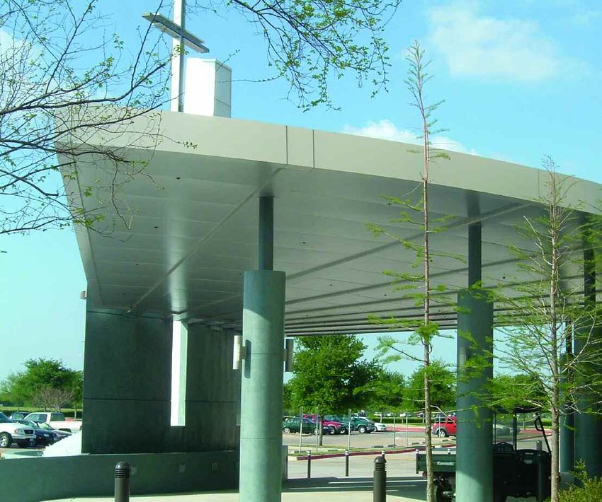
Canopies
Entry Vestibules
Building and Elevator Lobbies
Column Covers
Beam Cladding
Equipment Screening
Roof Screens
Architectural Accents
Sun Control and Shading
4 1-800-647-3778 • www.armetco.comRWC - Rout & Return Wet Seal SECTION OF RWC ROUT & RETURN WET SEAL SYSTEM
GENERAL INFORMATION
The information in this manual has been prepared to assist the designer
and installer with the proper application of Armetco’s RWC4 ACM Wet
Seal System. Since each project is unique, the information is intended
to be used as a guideline and in no way ensures proper application of
ACM Wet Seal System panels.
ALUMINUM COMPOSITE MATERIAL
Aluminum Composite Material (ACM) is the material of choice
when panel flatness and a high performance finish are a must.
Made from two sheets of aluminum bonded to a thermoplastic core,
ACM is strong yet lightweight and, with the right product knowledge
and equipment, can be fabricated into panel systems that will
accommodate most of your cladding needs.
Armetco Systems offers a complete line of ACM products, systems
and services. With multiple attachment systems and access to all of
the major Aluminum Composite Material manufacturers, Armetco
has an ACM solution for all applications.
Armetco’s RWC4 rout and return system is a wet seal ACM wall
cladding system. The perimeter of the panel is routed and folded to
form a 1” return leg. The corners are sealed and reinforced with
corner plates. Extruded aluminum stiffeners are applied with
structural adhesive on panels over 20 sf. Factory applied .080
aluminum attachment clips are applied with modified truss screws
in a staggered application. Panels shall attach to 18 gauge (min.)
subgirts or hat channel at 16” o.c.
6. Handle panels with multiple faces by lifting and / or supporting
Every project is shipped complete with installation drawings, panel’s at all or at least two faces. Failure to do this can cause
installation instructions, detailed material lists, approved fabrication damage to corner clips and supports and may cause the face
tickets, and clearly marked crates and panels. sheet to split.
INSTALLATION
PROPER STORAGE 1. Install panels per Armetco installation instructions and
If panels are not to be used immediately, they should be stored in approved shop drawings. Refer to page 18 for installation
an area that is out of the way and suitable for storage until ready illustrations.
for installation. Continual moving of crates and / or panels will 2. If field verification of dimensions is required, record actual field
cause damage to panels. Panels intended for exterior use can be dimensions on 1 set of shop drawings and return to Armetco
stored outside. Store crates on a solid surface. Keep the material off engineering.
the ground and Do NOT store crates on surfaces that are subject to 3. Review and approve Armetco fabrication drawings as required.
mud or in drainage areas where water can reach panels. If crates 4. Check support framing to be sure area to receive panels is
are wrapped in plastic, cut several large slits on the sides to allow installed straight, plumb and in plane.
ventilation and reduce condensation. It is the responsibility of the 5. Inspect waterproofing membrane for proper installation and
contractor / panel erector to insure that panels are properly stored for rips or tears. If waterproofing membrane is not installed
at the jobsite. properly and in good condition, make necessary repairs or
notify contractor immediately. DO NOT PROCEED with
PROPER UNLOADING & HANDLING panel installation until waterproofing membrane is in
1. Inspect crates immediately for damage. Notify driver of any acceptable condition.
visible damage and record damage on driver’s copy of 6. Install panels true, plumb, level and spaced properly (See
shipping bill. illustration on page 18).
2. Inspect contents of crates within 24 hours of delivery
3. Panel crates must be lifted from the bottom skid.
4. For hoisting, use proper lifting straps that have been inspected
and are in good condition. DO NOT USE CABLE OR ROPE.
5. Place panels in area that they can be stored safely until ready
for installation. Do not move crates and / or panels any more
than absolutely necessary. This will cause damage to panels.
1-800-647-3778 • www.armetco.com 5SPECIFICATIONS
B. Design Requirements:
1. Fabricator shall provide system design including
anchorage to structural system and modifications that
are necessary to meet specified requirements and
maintain visual design concepts.
2. Drawings and specifications are an outline of criteria
and performance requirements for the System.
Requirements specified or indicated by details are
intended to establish basic dimensions of module and
sight lines and profiles of members. Include
modifications or additions required to meet specified
requirements and maintain the visual design concept.
3. Contract Documents do not necessarily indicate or
describe total work required for completion of Work.
Furnish and install all items required for complete
installation.
4. Dimension and profile adjustments may be made in
proposed design in interest of fabrication or erection
methods or techniques, weatherability factor or ability
of design to satisfy design and performance
requirements provided that design intent and intent of
Contract Documents are maintained.
5. No visible fasteners, telegraphing or fastening on the
panel faces or any other compromise of a neat and
flat appearance is allowed.
6. Attachment Considerations: Account for expansion
PART 1 GENERAL and contraction movements so there is no possibility
of loosening, weakening, or fracturing connections.
1.1 SUMMARY
A. Section Includes: 1.3 PERFORMANCE REQUIREMENTS
1. Aluminum composite building panels as indicated on A. This is a performance specification; panel systems that
the project drawings and as specified herein. are not in compliance with the required performance
2. Supplementary subgirts, clips, anchoring devices, standards listed herein are unacceptable.
fasteners, and accessories. B. Provide a composite building panel system, which has
B. Related Documents: General and Supplementary been pretested, by an independent testing laboratory to
Conditions of the Contract, Division 1 General provide specified resistance to air and water infiltration
Requirements, and Drawings are applicable to this and structural deflection, when installed. Systems that
Section. are not pretested and certified by an independent
laboratory prior to bid are unacceptable. The use of a
SYSTEM DESCRIPTION panel manufacturer’s generic tests reports is
A. System Requirements unacceptable; the tests must be for the specific system
1. Rout and Return Wet Seal: Wet Seal aluminum submitted by the panel system engineer and fabricator.
composite panel system with intermittent clip C. Structural Performance
attachment. System must provide a wet seal (caulked) 1. Panels shall be designed to withstand the Design Wind
reveal joint as detailed on drawings. The sealant type Load based upon the local building code, but in no
shall be as specified in Section______ and with case less than 20 lb/ft2 and 30 lb/ft2 on parapet and
foamed type backer rod as indicated on architectural corner panels. Wind load testing shall be conducted
drawings. in accordance with ASTM E 330 to obtain the
2. Basis of Design: Armetco Systems RWC Rout and following results.
Return Wet Seal System: Provide complete panel 2. Normal to the plane of the wall between supports,
system as manufactured by ARMETCO SYSTEMS, deflection of the secured perimeter-framing members
INC., 11647 Armetco Drive, Justin, TX PH 800-647- shall not exceed L/175 or 3⁄4” (19mm), whichever is less.
3778 or other manufacturers whose materials offer 3. Normal to the plane of the wall, the maximum panel
the same function, performance and have received deflection shall not exceed L/60 of the full span.
prior approval by the Architect. Approval shall be 4. Maximum anchor deflection shall not exceed 1⁄16”
based upon test results indicating compliance with the (1.6mm).
specified performance requirements.
6 1-800-647-3778 • www.armetco.comSPECIFICATIONS
5. At 1-1/2 times design pressure, permanent deflections 2. Panel System Fabricator shall be approved by the
of framing members shall not exceed L/100 of span manufacturer.
length and components shall not experience failure of C. Installer Qualifications:
gross permanent distortion. At connection points of 1. Engage an experienced installer who has completed
framing members to anchors, permanent set shall not metal wall panel projects similar in material, design,
exceed 1⁄16” (1.6mm). and extent to that indicated for this project and with a
D. Static Air Infiltration: record of successful in-service performance.
Limit air infiltration through system to 0.06 cfm per 2. The panel system installer shall be responsible for a
square foot of wall area measured at an air pressure complete, sealed, and weather tight installation.
difference of 6.24 psf as measured in accordance with D. The panel system fabricator will prepare the shop
ASTM E 283 test. drawings in accordance with their standard published
E. Static Water Infiltration: product data and criteria established by others. The
a. Design system so that there is no water leakage general contractor and subcontractor shall be
under static air pressure with an air pressure responsible to verify the information contained therein
difference equal to 20 percent of the positive including all dimensions. In the interest of maintaining
design wind pressure with a minimum of 6.24 psf job schedules, the panel system fabricator will fabricate
and a maximum of 12.0 psf as measured in all of the materials from the approved set of shop
accordance with ASTM E 331test. drawings. If field verification of dimensions is required
b. Design system so that there is no water leakage the general contractor/subcontractor shall be responsible
under dynamic air pressure with an air stream to supply these dimensions to the panel system fabricator
equivalent to a static air pressure equal to 20 prior to engineering/fabricating of the materials.
percent of the positive design wind pressure with a Discrepancies found during field verification shall be
minimum of 6.24 psf and a maximum of 12.0 psf. corrected by the general contractor at no cost to the
panel system fabricator.
c. Water leakage is defined as any water that E. System: Submit engineer’s test reports certifying that
appears on any normally exposed interior fabricated panel system meets performance
surface. requirements specified.
F. Items Specifically Prohibited: F. Professional Engineer Qualifications: A professional
a. Exposed fasteners. engineer who is legally qualified and experienced in
b. External flashing at corners. providing engineering services of the kind indicated.
1.4 SUBMITTALS 1.6 DELIVERY, STORAGE AND HANDLING
A. Submit in accordance with Section ___________. A. Deliver metal wall panels and other manufactured items so
B. Submit samples of typical aluminum composite as not to be damaged or deformed. Package metal wall
panels, of type, thickness and finish specified. panels for protection during transportation and handling.
C. Product Data: Submit panel manufacturer’s product B. Unload, store and erect metal wall panels in a manner to
data, consisting of complete product description and prevent bending, warping, twisting, and surface damage
specification. in accordance with manufacturer’s recommendations.
D. Shop Drawings: Show fabrication and installation C. Store composite wall panels vertically, covered with
layouts of Aluminum Composite Panels; details of edge suitable weathertight and ventilated covering. Store
conditions, joints, panel profiles, corners, anchorages, panels to ensure dryness, with positive slope for drainage
attachment system, trim, flashings, closures, and of water. Do not store panels in contact with other
accessories; and special details. materials that might cause staining, denting, or other
E. Product Test Reports: Indicate compliance of surface damage. Do not allow storage space to exceed
Aluminum Composite Panel assemblies and materials 120 deg F.
with performance and other requirements based on D. Protect strippable protective covering on metal wall
comprehensive testing of current products. panels from exposure to sunlight and high humidity,
except to extent necessary for period of metal wall panel
1.5 QUALITY ASSURANCE Installation.
A. Manufacturer Qualifications:
1. Products covered under this Section shall be produced 1.7 WARRANTY
by a single manufacturer unless otherwise specified. A. Refer to and conform to requirements in Section ______.
2. Manufacturer shall submit evidence of having not less B. Factory Finish: Provide manufacturer’s 10 year warranty
than 10 years successful production of this product. stating finish will be:
B. Fabricator Qualifications: 1. Free of fading of color change in excess of 5 NBS
1. Panel System Fabricator shall submit evidence of skill units as measured per ASTM D 2244.
and not less than 5 years specialized experience with 2. Will not chalk in excess of maximum 8 units change
this product. when measured in accordance with ASTM A 214.
1-800-647-3778 • www.armetco.com 7SPECIFICATIONS
1.8 PROJECT CONDITIONS iii. 22.5 in pound/inch after 21 days soaking in
A. Field Measurements: Verify location of structural water at 70 degree F.
members and openings in substrates by field 5. Tolerances:
measurements before fabrication and indicate a) Panel Bow: 0.8 percent maximum of panel
measurements on Fabrication Approval Drawings. dimension in width and length for 72 inch panel.
B. Established Dimensions: Where field measurements b) Maximum Deviation from Panel Flatness: 1/8
cannot be made without delaying the Work, either inch in 5 feet on panel in each direction for
establish opening dimensions and proceed with assembled units, non-cumulative.
fabricating wall panels without field measurements. 6. Fire Performance
Coordinate wall construction to ensure actual locations of a) Flame Spread: 0 per ASTM E 84.
structural members and to ensure opening dimensions b) Smoke Developed: 0 per ASTM E84.
correspond to established dimensions. c) Surface Flaming: None per ASTM E 162.
d) No flame spread along interior face or penetration
through wall assembly per UBC 17-5.
PART 2 PRODUCTS
2.3 ACCESSORIES
2.1 MANUFACTURERS A. Attachment Clips: Minimum.080 aluminum
A. A specific product or material manufactured by any of the B. Composite Panel Stiffener:
following listed manufacturers is acceptable only if the 1. Aluminum extrusion or galvanized channel as
specific product or material can evidence compliance indicated on Drawings.
with requirements of the Contract Documents. 2. Maximum Spacing: 1/20 square feet of panel area.
1. Reynobond by Alcoa Cladding Systems 3. Panels in excess of 19.99 square feet: Stiffeners
2. Alucobond by Alcan Composites USA required.
3. Alpolic by Mitsubishi Chemical America Inc. 4. Calculate additional stiffeners at high wind load areas.
B. Substitutions: Submit in accordance with Section ______. 5. Attach with structural tape or silicone.
C. Subgirts and hat Channels:
2.2 MATERIALS 1. Minimum 18 gauge galvanized steel.
A. Composite Panel: 2. Maximum spacing 24” o.c.
1. Two sheets of aluminum sandwiching a core of D. Sealants: Sealants for a complete panel system shall be
extruded thermoplastic material formed in continuous part of this section. Sealant type is to be structural silicon
process with no glues or adhesives between dissimilar equal to Dow Chemical 795, supplied and installed by
materials. the panel installer. Color to be selected by architect from
2. Products laminated sheet by sheet or in batch process manufacturer’s standard color card. All metal surfaces
using glues or adhesives between materials shall not to be primed per recommendations and instructions of
be acceptable. sealant manufacturer prior to sealant installation.
3. Aluminum faced panel with thermoplastic core. E. Flashing Materials: Fabricate from 0.030 inch minimum
4. Panel Thickness: 4 mm (0.157 inch) – Composite thickness aluminum sheet painted to match the adjacent
Panel. panel system where exposed. Provide a lap strap under
5. Aluminum Face and Backer Sheet: Minimum 0.020 the flashing at abutted conditions and seal lapped
inches thick. surfaces with a full bed of non-hardening sealant.
6. Aluminum Alloy: AA 30036 with coated finish. F. Fasteners: Concealed; non-corrosive; as recommended
B. Product Performance Requirements by panel manufacturer and installer. Do not use exposed
Tolerances: fasteners.
1. Panel Bow: Maximum 0.8 percent of panel dimension
in width and length. 2.4 FINISHES
2. Panel Dimensions: Allowance for field adjustments, as A. General: Comply with NAAMM “Metal Finishes Manual”
recommended by manufacturer, where final dimensions for recommendations relative to application and
cannot be established by field measurement before designations of finishes.
completion of panel manufacturing. B. High-Performance Organic Finish: AA-C12C42R1x
3. Panel lines, breaks and angles shall be sharp, true (Chemical Finish: cleaned with inhibited chemicals;
and surfaces free from warp or buckle. Chemical Finish: acid-chromate-fluoride-phosphate
4. Bond Integrity: Per ASTM D 1781, no adhesive failure conversion coating; Organic Coating: as specified
of bond between core and skin nor cohesive failure below). Prepare, pretreat and apply coating to exposed
within core below the following values: metal surfaces to comply with coating and resin
a) Bond Strength: 214 psi, vertical pull. manufacturers’ written instructions.
b) Peel Strength:
i. 22.5 in pound/inch as manufactured.
ii. 22.5 in pound/inch after 8 hours in water at
200 degrees F.
8 1-800-647-3778 • www.armetco.comSPECIFICATIONS
1. Fluoropolymer Two-Coat System: Manufacturer’s F. Do not install component parts that are observed to be
standard two-coat, thermocured system consisting of defective, including warped, bowed, dented, abraised,
specially formulated inhibitive primer and and broken members.
fluoropolymer color topcoat containing not less than G Do not cut, trim, trim weld, or braze component parts
70 percent polyvinylidene fluoride resin by weight, during erection in a manner which would damage the
complying with AAMA 620. finish, decrease strength, or result in visual imperfection
2. Fluoropolymer Three-Coat System: Manufacturer’s or a failure in performance. Return component parts
standard three-coat, thermocured system consisting which require alteration to shop for fabrication, if
of specially formulated inhibitive primer, possible, or for replacement with new parts.
fluoropolymer color coat, and clear fluoropolymer H. Separate dissimilar metals and use gasketed fasteners
topcoat, with both color coat and clear topcoat where needed to eliminate the possibility of corrosive or
containing not less than 70 percent polyvinylidene electrolytic action between metals.
fluoride resin by weight, with a minimum total dry film
thickness of 1.5 mil; complying with AAMA 620. 3.3 ADJUSTING AND CLEANING
3. Color and Gloss: As selected from manufacturer’s A. Remove and replace panels damaged beyond repair as
standard colors. a direct result of the panel installation. After installation,
C. Anodized: panel repair and replacement shall become the
Clear Coating: AA-M12C22A41, Architectural Class I responsibility of the General Contractor.
Color Coating: AA-M12C22A41, light bronze, medium B. Repair panels with minor damage.
bronze and black, Architectural Class I C. Remove masking (if used) as soon as possible after
D. Polyester installation. Masking intentionally left in place after
a. Fluoropolymer and acrylic resin; baked paint panel installation on an elevation, shall become the
system, factory applied, baked-on polyester or responsibility of the General Contractor.
acrylic resin based paint coating system which D. Any additional protection, after installation, shall be the
meets performance specification AAMA 2603. responsibility of the General Contractor.
END OF SECTION
PART 3 EXECUTION
3.1 INSPECTION
A. Surfaces to receive panels shall be even, smooth, sound,
clean, dry and free from defects detrimental to work.
Notify contractor in writing of conditions detrimental to
proper and timely completion of the work. Do not
proceed with erection until unsatisfactory conditions have
been corrected.
B. Surfaces to receive panels shall be structurally sound as
determined by a registered Architect/Engineer.
3.2 INSTALLATION
A. Erect panel plumb, level, and true.
B. Attachment system shall allow for the free and noiseless
vertical and horizontal thermal movement due to
expansion and contraction for a material temperature
range of -20° F to +180° F (-29° C to +82° C). Buckling
of panels, opening of joints, undue stress on fasteners,
failure of sealants or any other detrimental effects due to
thermal movement will not be permitted. Fabrication,
assembly, and erection procedure shall account for the
ambient temperature at the time of the respective
operation.
C. Panels shall be erected in accordance with an approved
set of shop drawings.
D. Anchor panels securely per engineering
recommendations and in accordance with approved
shop drawings to allow for necessary thermal
movement and structural support.
E. Conform to panel fabricator’s instructions for installation
of concealed fasteners.
1-800-647-3778 • www.armetco.com 9D16
D15
WALL SECTION WALL SECTION WALL SECTION
10 1-800-647-3778 • www.armetco.comD16
D6
BUILDING ELEVATION
D2
N WALL SECTION
1-800-647-3778 • www.armetco.com 11DETAILS
1/2" HAT CHANNEL
TYPICAL
3/4" #10 MODIFIED
TRUSS SCREW
@ 24" O.C. MAX.
3/4" #10 MODIFIED
TRUSS SCREW
@ 24" O.C. MAX.
1/2"
CONTINUOUS SILICONE
SEALANT AND
BACKER ROD
FACTORY APPLIED
.080 ALUMINUM
ATTACHMENT CLIP
4mm ALUMINUM
COMPOSITE PANELS
EXT. SHEATHING OVER
METAL STUD FRAMING
MOISTURE
BARRIER
1 1/4" 1/2"
TYPICAL HORIZONTAL JOINT
TYPICAL HORIZONTAL JOINT D1
12 1-800-647-3778 • www.armetco.comDETAILS
ALUMINUM FLASHING CAP
SLOPE
FIELD APPLIED
.080 ALUMINUM
ATTACHMENT CLIP
MOISTURE
BARRIER
HWH TEK #3 WITH
NEOPRENE WASHER
1/2" HAT CHANNEL
1/2"
CONTINUOUS
CLEAT
MOISTURE
BARRIER
1/2" HAT CHANNEL
1 1/4"
EXT. SHEATHING OVER TYPICAL
METAL STUD FRAMING
4mm ALUMINUM
COMPOSITE PANEL
4mm ALUMINUM
COMPOSITE PANEL
1/2"
3/4" #10 MODIFIED
3/4" #10 MODIFIED TRUSS SCREW
TRUSS SCREW @ 24" O.C. MAX.
@ 24" O.C. MAX.
1 3/4"
FACTORY APPLIED
.080 ALUMINUM EXT. SHEATHING OVER
ATTACHMENT CLIP METAL STUD FRAMING
CONTINUOUS SILICONE
SEALANT AND
BACKER ROD SHEET METAL
PARAPET COPING CAP
TYPICAL VERTICAL JOINT SHEET METAL
TYPICAL VERTICAL JOINT D2 PARAPET COPING CAP D3
CONTINUOUS SILICONE
SEALANT AND
BACKER ROD
FIELD APPLIED
.080 ALUMINUM
ROOFING SLOPE ATTACHMENT CLIP
MEMBRANE
1/2" HAT CHANNEL
HWH SMS WITH
NEOPRENE WASHER
MOISTURE
BARRIER
AA
ACM CORNER
ANGLE BRACE 4mm ALUMINUM
AT RETURN LEGS COMPOSITE PANEL
FIELD APPLIED
.080 ALUMINUM
ATTACHMENT CLIP
SILICONE
SEALANT AND
BACKER ROD RADIUSED CORNER
RADIUSED CORNER
BATT INSULATION
4mm ALUMINUM
COMPOSITE PANEL
EXT. SHEATHING 4mm ALUMINUM
OVER METAL STUD COMPOSITE PANEL
1 3/4"
FRAMING
1/ 2 "
CONTINUOUS SILICONE
COMPOSITE PANEL SEALANT AND
BACKER ROD
PARAPET COPING CAP
COMPOSITE PANEL
PARAPET COPING CAP D4 D5
1-800-647-3778 • www.armetco.com 13DETAILS
CONTINUOUS SILICONE
SEALANT AND
BACKER ROD
FIELD APPLIED
.080 ALUMINUM
ATTACHMENT CLIP
4mm ALUMINUM
COMPOSITE PANEL
EXT. SHEATHING OVER
METAL STUD FRAMING
BATT
INSULATION
MOISTURE BARRIER
4mm ALUMINUM
COMPOSITE PANEL
.080 ALUMINUM
ATTACHMENT CLIP
STRUCTURAL
COLUMN
CONTINUOUS SILICONE
SEALANT AND
BACKER ROD
DRIP FLASHING
SET IN SEALANT
BASE CONDITION
AS OCCURS
BASE
SQUARECOLUMN
SQUARE COLUMN D6 BASE D7
MOISTURE BARRIER
4mm ALUMINUM
COMPOSITE PANEL EXT. SHEATHING OVER
METAL STUD FRAMING
EXT. SHEATHING OVER
METAL STUD FRAMING
1/2" HAT CHANNEL
BATT
INSULATION
BATT
INSULATION
1/2" HAT CHANNEL
.080 ALUMINUM
ATTACHMENT CLIP
BEYOND
MOISTURE BARRIER
4mm ALUMINUM
COMPOSITE PANEL
.080 ALUMINUM
ATTACHMENT CLIP
CONTINUOUS SILICONE
SEALANT AND
CONTINUOUS SILICONE BACKER ROD
SEALANT AND
BACKER ROD
GLAZING SYSTEM
DRIP FLASHING AS OCCURS
SET IN SEALANT
BASE CONDITION
AS OCCURS
BASE
HEADER AT
HEADER
FLUSH CONDITION AT
BASE D8 FLUSH CONDITION D9
14 1-800-647-3778 • www.armetco.comDETAILS
BATT
INSULATION
BATT INSULATION
MOISTURE
BARRIER
EXT. SHEATHING OVER
METAL STUD FRAMING
6" MIN.
MOISTURE ACM CORNER
BARRIER
ANGLE BRACE AT
RETURN LEGS FIELD APPLIED
EXT. SHEATHING OVER .080 ALUMINUM
METAL STUD FRAMING ATTACHMENT CLIPS
4mm ALUMINUM
COMPOSITE PANELS
4mm ALUMINUM GLAZING SYSTEM
AS OCCURS CONTINUOUS SILICONE
COMPOSITE PANEL SEALANT AND
1/2" HAT CHANNEL BACKER ROD
BACKER ROD
AND SEALANT
.080 ALUMINUM
ATTACHMENT CLIP BEYOND
SOFFIT RETURN
JAMB AT
FLUSH CONDITION
JAMB AT
FLUSH CONDITION D10 SOFFIT RETURN D11
MOISTURE
BARRIER
4mm ALUMINUM
COMPOSITE PANELS
BATT INSULATION
EXT. SHEATHING OVER
METAL STUD FRAMING
ACM CORNER
ALUMINUM ANGLE BRACE
STOREFRONT
AT RETURN LEGS
SILICONE
SEALANT AND
BACKER ROD
.080 ALUMINUM
.080 ALUMINUM ATTACHMENT CLIP
ATTACHMENT CLIP
CONTINUOUS SILICONE
SEALANT AND
MOISTURE BACKER ROD
BARRIER
BATT INSULATION ALUMINUM
STOREFRONT
EXT. SHEATHING OVER
METAL STUD FRAMING
4mm ALUMINUM
COMPOSITE PANELS
HEADER AT
JAMB AT RECESSED WINDOW
RECESSED WINDOW
JAMB AT HEADER AT
RECESSED WINDOW D12 RECESSED WINDOW D13
1-800-647-3778 • www.armetco.com 15DETAILS
BATT
INSULATION
BATT INSULATION
CONTINUOUS SILICONE
ACM ANGLE BRACE SEALANT AND
AT RETURN LEGS BACKER ROD
MOISTURE FIELD APPLIED
BARRIER .080 ALUMINUM
ATTACHMENT CLIP
EXT. SHEATHING OVER
METAL STUD FRAMING 1/2" HAT CHANNEL
CONTINUOUS SILICONE MOISTURE
SEALANT AND BARRIER
BACKER ROD EXT. SHEATHING OVER
METAL STUD FRAMING
FIELD APPLIED
.080 ALUMINUM
ATTACHMENT CLIP 1/2" HAT CHANNEL
4mm ALUMINUM
1/2" HAT CHANNEL COMPOSITE PANELS
4mm ALUMINUM
COMPOSITE PANELS
INSIDE CORNER
INSIDE CORNER
INSIDE CORNER D14 INSIDE CORNER D15
1/2" HAT
CHANNEL
BATT
INSULATION
GLAZING SYSTEM
MOISTURE
BARRIER
1/4"
RECESSED BACKER
ACM CORNER ROD AND
ANGLE BRACE SILICONE SEALANT
AT RETURN LEGS
FACTORY APPLIED ANGLE
SET IN SILICONE SEALANT
4mm ALUMINUM
COMPOSITE PANELS 4mm ALUMINUM
COMPOSITE PANELS
EXT. SHEATHING OVER CONTINUOU SILICONE FIELD APPLIED
METAL STUD FRAMING SEALANT AND .080 ALUMINUM
BACKER ROD ATTACHMENT CLIP
OUTSIDE CORNER GLAZED-IN PANEL
OUTSIDE CORNER D16 GLAZED-IN PANEL D17
16 1-800-647-3778 • www.armetco.comDETAILS
SLOPE ALUMINUM STIFFENERS
AT 30" O.C. MAX.
MOISTURE BARRIER
4mm ALUMINUM
COMPOSITE PANELS
EXT. SHEATHING OVER
METAL STUD FRAMING
FIELD APPLIED
.080 ALUMINUM
ATTACHMENT CLIP
1/2" HAT CHANNEL
CONTINUOUS SILICONE NOTE:
SEALANT AND PANELS OVER 24" IN WIDTH OR HEIGHT
BACKER ROD
REQUIRE STIFFENERS AT 30" O.C MAX.
CANOPY NOSE
STIFFENER PROFILE
STIFFENER LAYOUTS
CANOPY NOSE D18 STIFFENER LAYOUTS D19
1-800-647-3778 • www.armetco.com 17INSTALLATION INSTRUCTIONS
SHIM AS REQUIRED
PLUMB PANELS
CONTROL LINE
AS YOU GO
ACM PANEL
FACE OF PANEL ± 6"
#8 MODIFIED TRUSS
CENTERLINE OF JOINT=
SCREW (SUPPLIED)
CENTERLINE OF HAT
.080 ALUMINUM
ATTACHMENT CLIP
(SUPPLIED)
2. The first panel (A) is set 1⁄2" above the floor 3. The second panel (B) is installed on the
1. First set up a level control line several using shims. Measure down from your pins of the adjacent panel in the desired
inches above the panel. This way you control line to make sure the panel is direction using 1/2” shims between the
can measure down to the top of the level. It may be necessary to use shims to panels to insure a consistent joint. Shim as
panel. Then you can start putting up make sure the panel is level and plumb. required to keep panels level and plumb.
your subgirt. Shim the subgirts as
required to insure that surface to
receive panel is plumb and true.
Locate and install clips on panels
keeping in mind that clips on adjacent
panels need to be offset or staggered.
5. The next panel (D) is set on
4. Working vertically, the next panel the male leg of the lower
(C) is set on the lower panel panel using 1⁄2˝ shims to
using 1⁄2˝ shims to insure a insure a consistent joint.
consistent joint. Make sure to Make sure to align with the
align the panel with the lower panels already hung. Level
panels, level & plumb as you go. and plumb as you go.
8. When caulking to masonry or a porous
material it may be necessary to tape the
edge of the joint to keep the caulk off
6. When you have an area installed you 7. When you have the plastic removed,
the adjacent material. A silicone sealant
can go back and start peeling the install the backer rod in the joints as
can be very hard to clean off masonry.
plastic. You may want to just peel the shown. for a 1⁄2˝ joint you will want to
When it is time to tool the caulk, a tool
plastic out of the joints and leave it on use a 7⁄8˝ backer rod. The backer needs
with a convex edge is recommended to
the face of the panel. to be a maximum of 3⁄8˝ deep into the
keep the caulk within the joint. Tooling
joint. You are then ready to start
should be done with one pass with light
caulking for the optimum expansion it
pressure. This can be one of the most
is suggested that a 2 to 1 ratio (width
important jobs. Take your time.
to depth) is used.
18 1-800-647-3778 • www.armetco.com11647 Armetco Drive
Justin, Texas 76247
(800) 647 – 3778
(800) 618 – 7544 - FAX
www.armetco.com
E-Mail: info@armetco.comYou can also read