SMARTDRIVE EASY SYSTEM - HYDROSTATIC TRANSMISSION - Poclain Hydraulics
←
→
Page content transcription
If your browser does not render page correctly, please read the page content below
S M A R T D R IV E E A S Y S Y S T E M
H Y D R O S T A T IC T R A N S M IS S IO N

 T E C H N I C A L           C A T A L O G
SmartDrive Easy System                                                                                        POCLAIN HYDRAULICS

Methodology :
This document is intended for manufacturers of machines that incorporate Poclain Hydraulics products. It describes the technical characteristics
of Poclain Hydraulics products and specifies installation conditions that will ensure optimum operation.
This document includes important comments concerning safety. They are indicated in the following way:

                                                Safety comment.

This document also includes essential operating instructions for the product and general information. These are indicated in the following way:

                                                Essential instructions.

                                                General information .

                                                Information on the model number.

                                                Weight of component without oil.

                                                Volume of oil.

                                                Units.

                                                Tightening torque.

                                                Screws.

                                                Information intended for Poclain-Hydraulics personnel.

The views in this document are created using metric standards.
The dimensional data is given in mm and in inches (inches are given in brackets in italic)

2                                                                                                                                     17/02/2021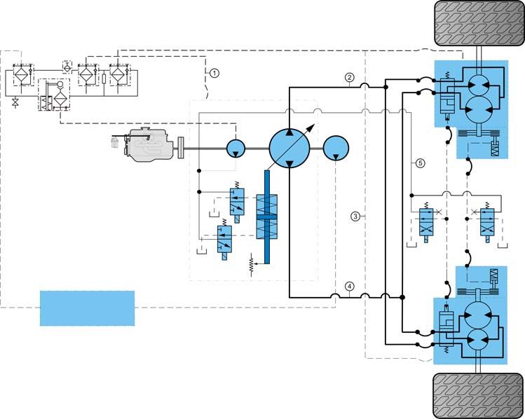
POCLAIN HYDRAULICS                                                        SmartDrive Easy System

                                  CONTENT

                                                                                                                    Characteristics
                           FOREWORD                                                                       5

                           Introduction                                                                   5
                           Characteristics of the regulating SmartDrive Easy™ ECU                         6
                           SmartDrive™ Easy input/output characteristics                                  7
                           Example of hydrostatic transmission control on a vehicle.                      8
                           Description of functions                                                       8
                           Auxiliaries                                                                   10
                           PC PHASES software combined with SmartDrive™ Easy                             14
                           Identification of the component                                               15
                           List of SmartDrive™ Easy components                                           16

                                                                                                                    Installation
                           INSTALLATION                                                                 17

                           Fitting the ECU                                                               17
                           Machine wiring recommendations                                                17
                           Description of pins                                                           18
                           Machine safety recommendations                                                19
                           Parking brake wiring recommendations                                          19
                           Installing the program                                                        20
                           System set-up                                                                 20
                           Set-up with the PHASES software application                                   20
                           Set-up with the hand held terminal (HHT)                                      21
                           Checking the installation before starting up                                  21
                           Checking of the electrical environment                                        22
                           First level diagnostic                                                        22
                           Checking of the hydraulic environment                                         22
                           Checking of hydraulic pressures                                               22
                           Starting up the engine                                                        23
                           Checking the system’s specific functions on wheel blocks                      23
                           Checking that the system works on wheels                                      23

17/02/2021                                                                                                      3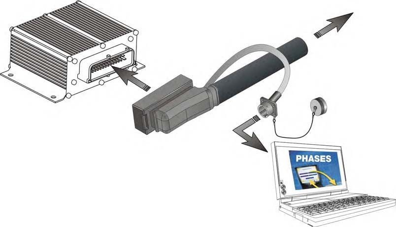
SmartDrive Easy System   POCLAIN HYDRAULICS

4                                      17/02/2021
POCLAIN HYDRAULICS                                                                                              SmartDrive Easy System

                                               FOREWORD
Introduction
Poclain Hydraulics has created and developed Smart Drive™ Easy, a system that simplifies and optimizes the running of hydrostatic
transmissions (e.g. mobile machinery).
It includes a computer that regulates the running of the hydrostatic transmission components (engine, hydraulic pump, hydraulic motors and
brakes) through sensors and actuators.
The on-board software calculates the machine's ground drive speed according to the driver setting, and the programmed acceleration and
deceleration ramps. These ramps, which are among the many parameters that enable the machine's behavior to be customized, determine
the vehicle's responsiveness and progressiveness.
The combination of the flexibility of the electronics and the power of the hydraulics makes this a system that can be adapted and set up for
all driving styles.

Functions
Specific to each application, in general, the system offers:
• Hydrostatic transmission control;

                                                                                                                                                   Characteristics
• Automatic displacement shift;
• Management of engine rotation speed;
• Power limitation;
• Anti-stall;
• Brake management;
• Signalling,
• Speed regulation (Cruise control),
• Limp mode management.

Examples of parameters
The parameters can be set for each application, using either the PHASES software or the portable hand held terminal. They may also be
subject to special access authorization.
They govern:
• The pump (displacement threshold for shifting from 1st to 2nd displacement; maximum permitted displacement);
• Engine (speed, etc.);
• Hydraulic motors (displacement);
• Brake valves (dynamic brake pressure at rest);
• Sensors (emergency brake pressure detection threshold, etc.);
• Cruise control function;
• Driving modes, (automotive etc).

                                                                                                                                                   Installation

17/02/2021                                                                                                                                     5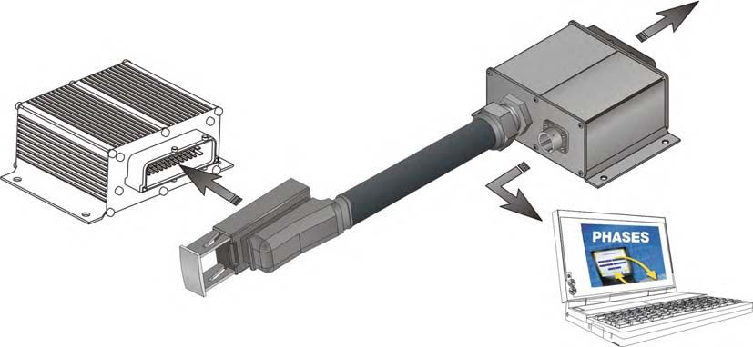
SmartDrive Easy System                                                                                    POCLAIN HYDRAULICS

Characteristics of the regulating SmartDrive Easy™ ECU

                                            Contact your PoclainHydraulics sales engineer for all
                                            adaptations.

Commercial name                                                        SD-EASY-PLUS                           SD-EASY-EXTENDED
Part number                                                               B20252M                                 B20253N
                                                                                              12 V DC
Supply voltage
                                                                                              24 V DC
                                                                                           - 40°C to 85°C
Operating temperature
                                                                                          [-40 °F to 185°F]
Overall dimensions                                                                           See below
Material                                                                                      Aluminum
                                                                                                0.5 kg
Mass
                                                                                               [1.1 lb]
                                                                                           4 x Ø 5.5 mm
Mounting
                                                                                           4 x [0.22" dia.]
ECU regulator protection index with its connectors                                     IP 65(weather proofing)
Maximum current                                                                                  14 A
Electrical protection                                                       Excess voltage, reverse polarity, short circuit
Microprocessor                                                                                  16 bits
Microprocessor frequency                                                                       25 MHz
Flash memory                                                              128 KByte                               256 KByte
ECU programming                                                  Programming with a PC using the PHASES™ software application
ECU set-up                                                                Set-up with the software PHASES™ or the HHT

Overall dimensions of the ECU regulator

Electromagnetic compatibility
Electromagnetic compatibility of moving machinery is required by the European Union. Manufacturers must submit a technical summary or one
of their machines to a qualified certification center.
The SmartDrive™ Easy ECU passed the electromagnetic compatibility tests for moving machinery components:
• ISO 14982: 1998
  Agricultural and forestry machinery - Electromagnetic compatibility;
• EN 13 309: 2000
  Construction machinery - Electromagnetic compatibility of machines with internal electrical power supply;
• EN 12895: 2000
  Industrial trucks - Electromagnetic compatibility.

6                                                                                                                                17/02/2021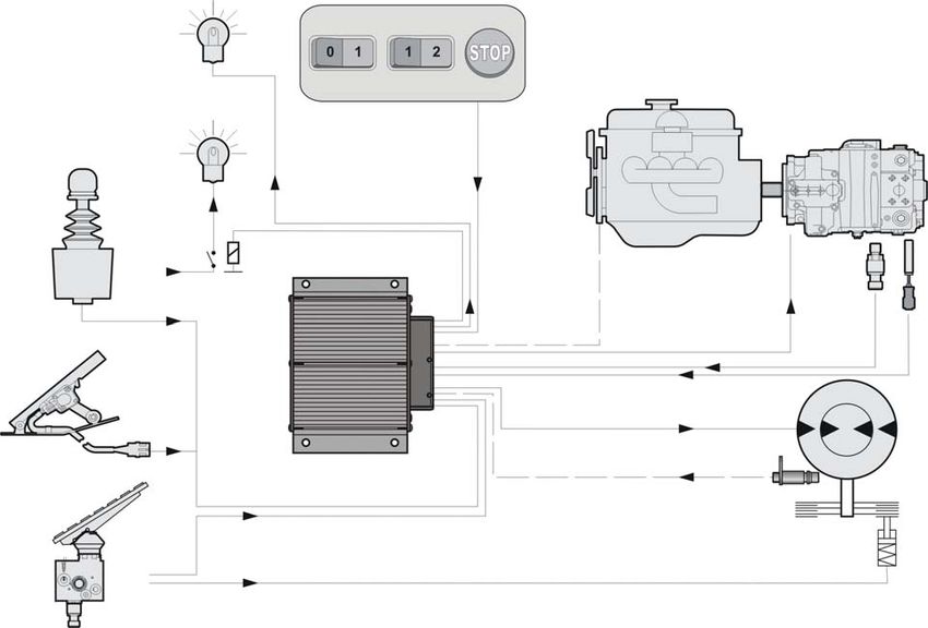
POCLAIN HYDRAULICS SmartDrive Easy System
SmartDrive™ Easy input/output characteristics
On-Off digital inputs (x 5)
These inputs are of the ground pin type.
They are protected against short circuits on the ground, battery, 5 V and 12 V.
Description Min. Max.
Maximum voltage for a low level 1.65 V
Minimum voltage for a high level 3.25 V
Allowable voltage 30 V
Maximum resistance of pin for a low level 1.5 k
Minimum resistance of pin for a high level 10 k
Analog inputs (x 5)
They are protected against short circuits on the ground, battery, 5 V and 12 V.
Characteristics
Description Min. Max.
Measurement range 0V 5V
Accuracy 1%
Allowable voltage 30 V
Input impedance 259 k
Frequency inputs (x 2)
The sensors read can be NPN, PNP and PUSH/PULL on the two frequency inputs.
The differential sensors can only be read on the frequency input 2.
Description Min. Max.
Measurement range 0 Hz 8 500 Hz
Allowable voltage 30 V
Digital outputs (x 4)
They are protected against short circuits at the ground, battery, 5 V and 12 V.
These outputs are protected against thermal overload.
Description Min. Max.
Maximum current 0.5 A under 12V / 0.25 A under 24V
Output voltage Vbat -1V Vbat
Configurable PWM outputs (x 2)
• Mode 2A (pins 30, 6, 16 and 19)
These outputs are protected against short circuits on the ground, battery, 5 V and 12 V.
These outputs are protected against thermal overload.
Description Min. Max.
Installation
Maximum current 0 2 A under 12 V / 1 A under 24 V
Maximum frequency 3.125 kHz
• Mode 125 mA (pins 16, 20, 30 and 34)
They are protected against short circuits on the ground, battery, 5 V and 12 V.
These outputs are protected against thermal overload.
Description Min. Max.
Measurement range 0 125 mA
Maximum frequency 3.125 kHz
Non-configurable PWM outputs (x 2)
• Mode 2A (pins 31, 35, 17 and 21)
These outputs are protected against short circuits on the ground, battery, 5 V and 12 V.
These outputs are protected against thermal overload.
Description Min. Max.
Maximum current 0 2 A under 12 V / 1 A under 24 V
Maximum frequency 3.125 kHz
17/02/2021 7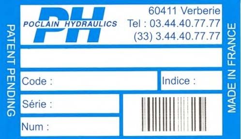
SmartDrive Easy System                                                                                                    POCLAIN HYDRAULICS

Example of hydrostatic transmission control on a vehicle.

                               Default

                                                           Road   Field

                                            Parking brake               Emergency stop
                               Stop

                                                                                                                                     C

                                                                                         Engin speed
                     Battery
     D

                                                                                           control
                                                                                                       B

                                                                                                                                      Pressure
                                                   A

                                                                                                                                                 Speed
                                                                                                       Pump displacement control

                                                                                  Motor displacement shift

     D
                                                                                  Hydraulic motor speed

                                          Acceleration / Deceleration

                                              Hydraulic braking

     D                                             Brake

Description :
 A - An SmartDrive™ Easy regulating ECU that controls transmission,
 B - An engine command with a CAN Bus link,
 C - A pump fitted with displacement control solenoids, a speed sensor and a 600-bar pressure sensor,
 D - A joystick or pedal, mode selection switch, default light, stop light, speed sensor display, etc.

Signalling
The ECU manages signalling (braking, reverse lights, warning beep, etc.) depending on the ground drive condition.

CAN Bus Communication
The ECU presents a standard 2.0A or the applied 2.0B CAN interface.
When connected to the machine’s CAN network, the SmartDrive™ Easy ECU can therefore:
• Receive messages (joystick, selectors, reading engine rotation speed, etc.)
• Send messages (engine setting, signalling, fault indicator, error message, etc.)

                                          CAN adjustment requires a configuration that depends on the
                                          complexity of the CAN architecture for each manufacturer.
                                          Contact your Poclain Hydraulics sales engineer.

Description of functions

Driving modes
The driver can have two standard operating configurations:

[ Road Mode ]
This is an automotive type of driving, similar to an automatic transmission. The transmission ratio is determined automatically by the load
management of the engine, pump displacement and hydraulic motor displacement. The load on the engine is therefore related to the vehicle
speed, resulting in the reduction of pollution and fuel consumption.

8                                                                                                                                                        17/02/2021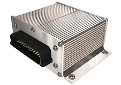
POCLAIN HYDRAULICS                                                                                                SmartDrive Easy System

[ Field Mode ]
The speed of the engine is constant; the auxiliary tools consume most of its power.

                                         It is possible to define other modes, depending on the nature
                                         of the work to be carried out and the environment. Contact
                                         your Poclain Hydraulics sales engineer.

The ground drive parameters may thus be different from one [ Field Mode ] to another.
Shifting between modes is done under different safety conditions managed by the SmartDrive™ Easy ECU.

Automatic displacement shift
The SmartDrive™ Easy transmission varies speed continually.
Depending on the acceleration or brake settings issued by the driver, hydraulic motor displacement shift is seamless. This is accomplished
by simultaneous pump displacement control and motor displacement shift control.
Therefore, since the operation is practically entirely automatic, the driver can focus on tasks with higher added value, such as the machine’s
working functions, and, particularly, tool management.

Management of engine rotation speed

                                                                                                                                                     Characteristics
The SmartDrive™ Easy ECU can fully manage the engine via the CAN Bus.
The ECU optimizes the rotation speed of the engine for the requested power level.

Anti-stall function
This function reduces the pump displacement to prevent the engine stalling if the power required by the hydrostatic transmission exceeds
the engine’s available power.

Limitation of ground drive power
Some machines have engines that are oversized for the ground drive power requirement when the on-board tools are turned-off [ Field
Mode ].
In [ Road Mode ], there is no protection and the engine's full power is available. Limiting the integrated power in a transmission controlled
by a SmartDrive™ Easy therefore protects the hydrostatic transmission from possible excess output, which could cause irreversible
damage over time.

Brake management

Service brake (dynamic)
   The brake pedal:
   • Activates mechanical braking,
   • Reduces pump displacement via the SmartDrive™ Easy ECU.
   The braking system is of the combined type, i.e. the mechanical braking torque combines with the hydrostatic transmission's braking
   torque (pump displacement reduced).
   The SmartDrive™ Easy manages the pump and hydraulic motor displacement reduction by taking account of the level of mechanical
   braking, so that the hydrostatic transmission prevents possible wheel lock.

Brake pedal only
   Adjusts the hydrostatic braking.

Parking brake
   The parking brake is held by the spring force.
   To deactivate this brake, the driver operates a switch, a lever or a foot control. These components then transmit pressure to the brake
   pistons, which cancel out the spring force.                                                                                                       Installation
Emergency stop

                                         If the parking brake switch is activated for an emergency stop,
                                         the mechanical parking brakes acts and the hydrostatic brake
                                         engages by means of a pump displacement ramp managed by
                                         the SmartDrive™ Easy.

Constant speed with combined auxiliary control
In [ Field Mode ], the machine’s ground drive speed remains constant in spite of the acceleration of the engine required for the auxiliary
functions.
The operator, now freed from controlling the speed, can concentrate on tasks with higher added value.

17/02/2021                                                                                                                                       9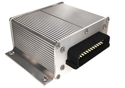
SmartDrive Easy System                                                                               POCLAIN HYDRAULICS

Auxiliaries

42-pin main connector

                                                                                                               Poclain Hydraulics
Characteristics                                        Description                             AMP reference
                                                                                                                  part number
Commercial name                                        KIT-CONNECTEUR-MAIN-SD-EASY                                 A02809D
                                                       AMP Connector                            1-967281-1
                                                       AMP protective cover                     0-965643-1
                                                       7 AMP female contacts                     929937-3
                                    Power              7 AMP insulants                           828905-1
Components
                                                       6 AMP stoppers                            828922-1
                                                       40 AMP female contacts                    962876-1
                                    Signals            40 AMP insulants                          963530-1
                                                       36 AMP stoppers                           963531-1
                                    For power pins     1.5 to 2.5 mm² [0.0023 to 0.004 in²]
Cable section
                                    For signal pins    0.5 to 1.0 mm² [0.0008 to 0.0015 in²]
                                    For power pins     2.2 to 3.0 mm² [0.0034 to 0.0046 in²]
Insulation diameter
                                    For signal pins    1.4 to 1.9 mm² [0.0021 to 0.003 in²]
Operating temperature               -40°C to 85°C [-40°F to 185°F]
Ingress protection                  IP 68

Mounting tools for the connector

Description                                                                                    AMP reference
Crimpers                                                                                         539635-1
Chuck-jaw for power spindles                                                                     539737-2
Chuck-jaw for control spindles                                                                   539651-2
Extractor for power spindles                                                                    1-1579007-6
Extractor for control spindles                                                                   726534-1

10                                                                                                                           17/02/2021
POCLAIN HYDRAULICS SmartDrive Easy System
Male connector communication
Commercial name KIT CONNECTEUR MALE COM SD
Part number A50515H
Characteristics
Compatibility SmartDrive™ Easy, SmartDrive™ Auto
Features
Manufacturer Amphénol
Receptacle PT02A12-14P023
Components Closing cap BECN1207
Seal JE12
Wire range 0,38 to 0,93 mm2
Insulation diameter 1,2 to 2,4 mm
Operating temperature -55°C to +125°C [-67°F to 257°F]
Ingress Protection IP68
Material Aluminium wit h plated nickel
Connector mounting
Strip the wires to a length of 5 mm [0.19 in].
Solder the wires onto the pins as shown in the table below.
N° pin SD Easyconnector Function N° pin male communication connector
7 5V RS 232 A
12 CAN L E, F
26 RX RS 232 H Installation
14 CAN H 120 K
27 TX RS 232 L
13 CAN H M, N
42 Ground P, R
Risk of damage to the serial port of the ECU.
When connecting an external equipment working with the RS232 link, be
sure to connect as following:
- RX RS 232 (Easy) TX RS232 (Various equipment)
- TX RS 232 (Easy) RX RS232 (Various equipment)
17/02/2021 11SmartDrive Easy System POCLAIN HYDRAULICS
SmartDrive™ Easy cable
Commercial name CABLE-SD-EASY-42-1000 CABLE-SD-EASY-42-5000
Part number A20311C A20313E
Function Connect a SmartDrive™ Easy or SmartDrive™ Auto ECU to the machine wiring and
have a communication connector.
Compatibility Transmission management with SmartDrive™ Easy or
SmartDrive™ Auto ECU.
Features
Lenght of cable 1m 5m
Material PVC
Number of wires 42
Sections of wires 1mm2
Layout
or
Electrical wiring
Pin Wire
The wires of the cable are numbered.
1 1
2 2
3 3
....
....
26 Not connected
27 Not connected
......
......
42 42
The non used wires should be individually insulated because of possible voltage.
12 17/02/2021POCLAIN HYDRAULICS SmartDrive Easy System
SmartDrive™ communication cable
Characteristics
Commercial name COM-CABLE-SD-1000 COM-CABLE-SD-5000
Part number A20360F A20361G
Function Connect a SmartDrive™ ECU communication elements to the machine wiring
Compatibility Electronic transmission management with SmartDrive™ ECU
Features
Lenght of cable 1m 5m
Material PVC
Number of wires 14
Sections of wires 0.22mm2
Layout
or
Electrical wiring
Pin Wire
A White
Installation
B Brown
C Green
D Yellow
E Gray
F Pink
H Blue
J Red
K Black
L Violet
M Gray/Pink
N Red/Blue
P White/Green
R Brown/Green
The non used wires should be individually insulated because of possible voltage.
17/02/2021 13SmartDrive Easy System POCLAIN HYDRAULICS
The characteristics and installation of the components below
are described in catalogue n° A01889D.
Joystick
Controls the direction of the ground drive and provides the acceleration/deceleration and speed settings.
Suspended or floor pedal
Controls the direction of the ground drive and provides the acceleration/deceleration and speed settings. Another pedal can also be used for
braking.
Position sensors
These potentiometers (rotary or linear) are linked to controls other than those described above, which already incorporate a potentiometer. They
indicate the position of the control levers.
Pressure sensors
They inform the ECU of the High Pressure Line pressure (from the 600-bar sensor) and the brake circuit pressure (from the 160-bar sensor).
Analogical temperature sensor
It informs the ECU of the High Temperature in the hydraulic circuit which can activate damaged modes (e.g.: translation speed decreasing in case
of overheating).
Options
Speed sensor.
See the motor technical catalogues.
PC PHASES software combined with SmartDrive™ Easy
PHASES™ enables :
Set-up
The settings of the SmartDrive™ Easy may need to be changed if there is a change in characteristics or operating conditions.
The PHASES™ software manages 3 access levels to settings:
• Service,
• Manufacturer,
• Expert.
The last two levels are restricted to technicians with specific training (access restriced through password).
Downloading
Using a PC and the PHASES™ software allows to :
• Download the software to the SmartDrive™ Easy;
• Send and retrieve set-up files.
The hand held terminal only allows you to modify the data item per item.
Any modification of the value of a setting must be carried out by
a qualified engineer trained by the machine manufacturer. The
Poclain Hydraulics technical support team can advise you in
defining your settings.
Modifications to the settings may require a new qualification of
the machine. If in doubt, contact your Poclain Hydraulics sales
engineer.
Calibration
The PHASES™ software allows to calibrate the minimum, maximum and neutral positions of the sensors installed on the machine in order to
optimize the system’s operation.
For further information, see PHASES™ user guide
no. 801378162C and HHT user guide no. A06618T.
Diagnostics
The PHASES™ software enables the user to download the system's operating data. The data collected is used to identify possible malfunctions.
Likewise, the hand held terminal is used to identify a malfunction through a system of codes and error messages.
Study of the system
Our sales engineers will analyze your specific needs to facilitate the integration of Poclain Hydraulics components into your system.
Training
Available on request.
14 17/02/2021POCLAIN HYDRAULICS SmartDrive Easy System
Identification of the component
F
B
SD-EASY-PLUS
E
B20252M
A
01
C
7572
D
Characteristics
A : Model code
e.g. SD-EASY-PLUS
B : Code (Part number):
e.g. B20252M
C : Serial number (Shop number):
e.g. 01
D : Number (Number of chronological order):
e.g. 7572
E : Country of manufacturing
F : Place of manufacturing
The part number must be given for all replacement part
orders.
Installation
17/02/2021 15SmartDrive Easy System POCLAIN HYDRAULICS
List of SmartDrive™ Easy components
ECU and its connections
Commercial name Part number
REGULATING ECU SD-EASY-EXTENDED B20253N
BOX CONNECTOR KIT-CONNECTEUR-MAIN-SD-EASY A02809D
COM SD MALE CONNECTOR KIT KIT-CONNECTEUR-MALE-COM-SD A50515H
SMARTDRIVE EASY CABLE (1 m) CABLE-SD-EASY-42-1000 A20311C
SMARTDRIVE EASY CABLE (5 m) CABLE-SD-EASY-42-5000 A20313E
COMMUNICATION CABLE (1 m) COM-CABLE-SD-1000 A20360F
COMMUNICATION CABLE (5 m) COM-CABLE-SD-5000 A20361G
CONNECTORS (For ECU and sensors) KIT-CONNECTEUR-SD-EASY A13016X
Setting parameters
Commercial name Part number
CONTROL SOFTWARE (including SD PC LT cable) PHASES Easy A04903E
CABLE (extra) CABLE SD PC LT 006142212S
SETUP TERMINAL (including SD HHT LT cable) TERMINAL EQ. ST2000 005142202A
CABLE (extra) CABLE SD HHT LT 006142213T
SD EASY COM ADAPTER CABLE DE COM SD EASY A05362D
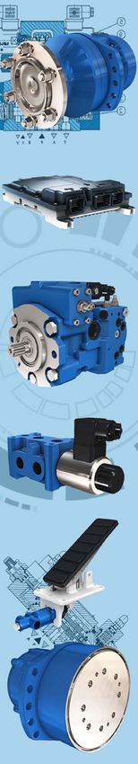
Auxiliaries
Commercial name Part number
600-bar PRESSURE SENSOR - 1/4G connection PRES-SENS-600B-G1/4-MP3 B58367R
160-bar PRESSURE SENSOR - 1/4G connection PRES-SENS-160B-G1/4-MP3 B58365P
600-bar PRESSURE SENSOR - 9/16 connection PRES-SENS-600B-9/16-MP3 B58366Q
160-bar PRESSURE SENSOR - M10 connection PRES-SENS-160B-M10-MP3 B58364N
PRESSURE SENSOR CABLE CABLE-PRESSURE-SENSOR-3M 003141105U
ANALOG TEMPERATURE SENSOR TEMP-SENS-G1/4-M12-7 B45088H
ELEC-CABLE-M12-180°-5000 A07468S
M12 CABLE FOR TEMPERATURE SENSOR
ELEC-CABLE-M12-90°-5000 A04999J
Control elements
Commercial name Part number
FLOOR PEDAL (provided with connector) ELEC-HORIZ-PEDAL-30°-DUAL A50838J
JOYSTICK (provided with connector) JOYSTICK-35°-HANDLE-LOCK 003442799X
KIT CONNECTEUR CAPT VIRAGE 007142222K
STEERING SENSOR CONNECTOR
KIT CONNECTEUR CAPT CDE SA 007142212Z
Hydraulic motor environment
Commercial name Part number
SPD-SENS-T4-12-44 B61287Q
SPEED SENSOR SPD-SENS-T4-12-53 B61288R
SPD-SENS-T4-12-62 B61289S
ELEC-CABLE-M12-180°-5000 A07468S
M12 CABLE FOR SPEED SENSOR
ELEC-CABLE-M12-90°-5000 A04999J
Commercial codes and item numbers may change during the lifetime
of the system. Contact your Poclain Hydraulics sales engineer.
16 17/02/2021POCLAIN HYDRAULICS SmartDrive Easy System
INSTALLATION
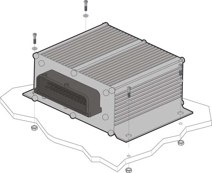
Fitting the ECU
The ECU must be fixed on a rigid support. Make sure that there is enough space to fit the connector.
4 x M5 screws, 8.8 class
Characteristics
Machine wiring recommendations
• All the cables must be encased in flexible metal or plastic sheaths;
• All cables or sheaths must be held well in place and locked in to prevent pull-ou;
• Bring the sheath supports close together;
• The sheaths must be able to slide into the anchoring;
• Avoid mechanical stresses in the cables;
• Do not place the cables or sheaths close to moving or vibrating parts;
• Do not lay the sheaths along sharp angles. Protect them at each bend;
• Avoid laying the sheaths too close to high heat sources;
• Use wires with abrasion-resistant sheaths;
• Use cables that resist temperatures between 85°C and 105°C close to heat sources;
• Separate power cables from control cables; Installation
• Pass the cables inside the machine, ensuring as much contact as possible with metal surfaces (steel). This will act as a shield against
electromagnetic radiation.
17/02/2021 17SmartDrive Easy System POCLAIN HYDRAULICS
Description of pins
Number each wire using numbered plastic rings. Each cable must be securely fixed to the machine with clips placed every 20 cm.
Sections are given (for information only) in mm² for a 10 meter length at an operating temperature of < 80 °C [176 °F].
Wire section
PIN J1 Function mm²
1 VBAT+ Battery power (+) 1.5 to 2.5
2 NC Not connected
3 NC Not connected
4 POUT1 Digital output 1 0.5 to 1
5 POUT4 Digital output 4 0.5 to 1
6 PWM1(-) 2A PWM1 terminal (-) in case of 2A command 0.5 to 1
7 5 V OUT 5V sensors power supply 0.5 to 1
8 12V OUT 12V sensors power supply 0.5 to 1
9 ANIN3 Analog input 3 0.5 to 1 ECU side view
10 FIN2_DIF+ Differential frequency input 2 (+) 0.5 to 1
11 DIN5 Digital input 5 0.5 to 1
12 CANL Low CAN signal 0.5 to 1
13 CANH High CAN signal 0.5 to 1
14 CANH_120 Connexion for CAN bus end 120 Ù 0.5 to 1
15 ANA GND Analog input ground 1.5 to 2.5
16 PWM2(+) PWM2 (+) terminal 0.5 to 1
17 PWM4(+) PWM4 (+) terminal 0.5 to 1
18 POUT3 Digital output 3 0.5 to 1
19 PWM2(-) 2A PWM2 terminal (-) in case of 2A command 0.5 to 1
20 PWM2(-) 120mA PWM2 terminal (-) in case of 120 mA command 0.5 to 1
21 PWM4(-) PWM4 (-) terminal 0.5 to 1
22 ANIN2 Analog input 2 0.5 to 1
23 ANIN5 Analog input 5 0.5 to 1
24 FIN2_DIF- Differential frequency input 2 (-) 0.5 to 1
25 DIN4 Digital input 4 0.5 to 1
26 RX232 Receive signal (serial link) 0.5 to 1
27 TX232 Transmit signal (serial link) 0.5 to 1
28 VBAT- (GND) Battery power (-) (ground) 1.5 to 2.5
29 VBAT+ Battery power supply (+) 1.5 to 2.5
30 PWM1(+) PWM1(+) terminal 0.5 to 1
31 PWM3(+) PWM3 (+) terminal 0.5 to 1
32 POUT2 Digital output 2 0.5 to 1
33 5 V OUT 5V sensors power supply 0.5 to 1
34 PWM1(-) 120mA PWM1 terminal (-) in case of 120 mA command 0.5 to 1
35 PWM3(-) PWM3 (-) terminal 0.5 to 1
36 ANIN1 Analog input 1 0.5 to 1
37 ANIN4 Analog input 4 0.5 to 1
38 FIN1 Frequency input 1 0.5 to 1
39 DIN1 Digital input 1 0.5 to 1
40 DIN2 Digital input 2 0.5 to 1
41 DIN3 Digital input 3 0.5 to 1
42 VBAT- (GND) Battery power (-) (ground) 1.5 to 2.5
Communication cable
Wire section
PIN J1 Function
mm²
A 5V OUT 5V sensors power supply 0.22
B NC Not connected
C NC Not connected ECU side view
D NC Not connected
E CANL Low CAN signal 0.22
F CANL Low CAN signal 0.22
H RxRS232 Receive signal (serial link) 0.22
J NC Not connected
K CANH_120 Connexion for CAN bus end 120 Ù 0.22
L TxRS232 Transmit signal (serial link) 0.22
M CANH High CAN signal 0.22
N CANH High CAN signal 0.22
P GND ground 0.22
R GND ground 0.22
18 17/02/2021POCLAIN HYDRAULICS SmartDrive Easy System
Machine safety recommendations
The machine manufacturer is responsible for safety mea-
sures during the installation of our products. They must com-
ply with applicable laws in the country or state.
Poclain Hydraulics recommends that you first do the wiring
for an emergency stop button that can be easily accessed by
the driver. The button should stop the engine and cut off the
power supply of the SmartDrive™ Easy.
All calculator and sensors connectors must be unplugged
Characteristics
during electrical welding operations.
A lamp on the dashboard must be wired parallel to the parking brake operating coil to give the actual status of the parking brake. The logic
must be as follows:
• Lamp on, parking brake applied;
• Lamp off, parking brake released.
To prevent vehicle movement during engine start, it is
recommanded to wire parking brake switch in serial with
starter.
Sensors
Sensors must be powered at (0V 5V) with the exception of
wheel speed and thermal sensors that need to be powered at
(0V 12V).
The proportional sensors used must have a variation range of
(0.5V to 4.5V ) at the output.
5V Power supply: 0.5V < output signal < 4.5V, signal weaker at rest than when operating, for example in the case of a pedal.
Potentiometer sensor specifications:
• Resistance < 5 k
• 1 k < sensor resistance < 10k (5k recommended)
A joystick must have at least 1 switch open in neutral, that is otherwise closed.
The switch in neutral can be replaced by a forward switch and a reverse switch that are both open in neutral and closed depending on the
required direction.
• The ground of the analog sensors must be directly connected to SmartDrive™ Easy analog ground (pin n°15). This analog ground has not
to be connected to VBAT-(ground) or vehicle chassis. Installation
Parking brake wiring recommendations
If the ECU controls also the parking brake, you must Bat.
IMPERATIVELY wire as shown opposite.
Warning: The switch used must-to be able to carry the current
which circulates in the solenoid brake (current can
exceed 2 ampers).
1- Exit orders parking brake.
2- Entry On/Off sensor.
3- Solenoid of parking brake
(if supplied = brake not applied).
4- Switch of parking brake.
5- Solenoid relay.
This wiring can authorise parking brake application by driver or by SmartDrive™ Easy.
17/02/2021 19SmartDrive Easy System POCLAIN HYDRAULICS
Installing the program
To work, your system needs an SmartDrive™ Easy ECU as well as the on-board software that will be loaded onto the computer.
There are two ways of loading the software.
• First solution:
Poclain Hydraulics or your distributor has sent you the on-board software on a CD-rom, by e-mail or by another means. Use the PC PHASES™
Easy software to transfer the application to the SmartDrive™ Easy ECU.
• Second solution:
You design your application directly with the PC PHASES™ Easy Design software. Follow the instructions described in documentation
N°801378162C and then use PHASES™ Easy Design to transfer the software to the SmartDrive™ Easy ECU.
System set-up
Use the PHASES software to set up the system.
For further information about the PHASES™ software application, consult the online help or PHASES™ catalogue.
For further information, see PHASES™ user guide
no. 801378162C and hand held terminal user guide
no. A06618T.
Set-up with the PHASES software application
Install the PHASES™ Easy software (see installation guide n° 801378162C).
Connect the ECU to the PC with the CABLE SD PC LT cable by connecting the PC's SUBD9 to the ECU's communication connector (serial link).
We propose three solutions for communicating with the SmartDrive™ Easy ECU:
1 - Via the communication connector installed on the machine. For the wiring of the connector see the table on page 16.
To machine
KIT-CONNECTEUR-MALE-COM-SD:
A50515H
20 17/02/2021POCLAIN HYDRAULICS SmartDrive Easy System
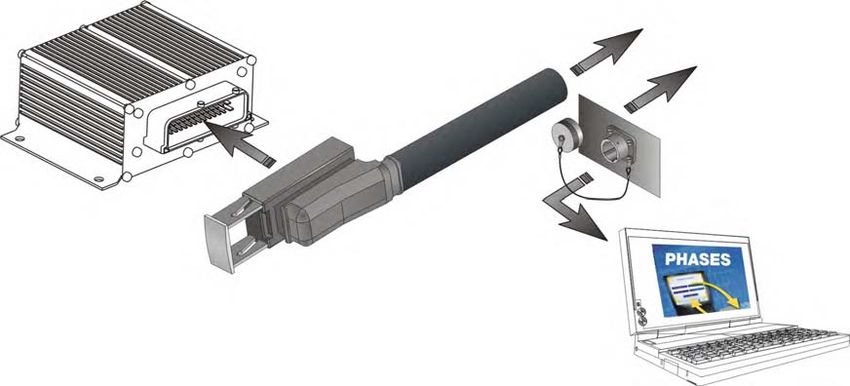
2 - Via the SmartDrive™ Easy communication adapter (Part number: A05362D). See the diagram below.
To the machine
connector
Characteristics
3 - Via SmartDrive™ Easy cable. See the diagram below.
To machine
SmartDrive™ Easy Cable:
A20311C or A20313E
Installation
Set-up with the hand held terminal (HHT)
The hand held terminal is used only to modify the settings directly in the ECU. There is no way of saving a configuration file.
Connect the ECU to the hand held terminal with the CABLE SD HHT LT cable.
See user guide n° A06618T to set the system with the hand held terminal.
Checking the installation before starting up
The elements to be checked depend on the application of each
vehicle. Please remember that each manufacturer is ultimately
responsible for checking their machinery at the end of the
line.
17/02/2021 21SmartDrive Easy System POCLAIN HYDRAULICS
Checking of the electrical environment
The PHASES™ software enables you to view any anomalies detected by the SmartDrive™ Easy ECU, by delivering an error code, a brief
explanation and a list of possible causes. In particular, it indicates:
• Short-circuit type electrical anomalies on the ground, or the 5V;
• Cabling errors: switch allocated/not allocated to a given part;
• input/output malfunctions.
The hand held terminal can also check these points without help files.
Calibration can detect cable configuration errors (see next
chapter).
First level diagnostic
Fault warning lamp on dashboard:
The warning lamp flashes if there is a fault. Otherwise, it remains off.
Checking of the hydraulic environment
Refer to the information on commissioning provided in the
"Motor generic installation" brochure n° 801478197L.
Checking of hydraulic pressures
Fit the machine temporarily with pressure gauges and check the against the table below.
Block diagram with
dual displacement motors
Auxiliaries
Pressure gauge Pressure Informations
bar [PSI]
1 0 - 4 [0 - 58] Pump case pressure
2 0 - 450 [0 - 6 530] HP (high pressure) pressure supply
3 0 - 4 [0 - 58] Motor case pressure
4 0 - 450 [0 - 6 530] HP (high pressure) pressure supply
5 0 - 40 [0 - 580] Charge pressure
22 17/02/2021POCLAIN HYDRAULICS SmartDrive Easy System
Starting up the engine
Place the machine on the wheel blocks.
Set up a safety area.
Observe all personnel safety instructions.
Put the F/N/R (Forward/Neutral/Reverse) shift lever in the neutral position. Apply the parking brake.
Switch on the ECU.
Start the engine, and wait until the charge pressure is established.
Press the emergency stop button and check that it stops the
engine and cuts off power to the SmartDrive™ Easy ECU.
Characteristics
Start the engine again and then use the PHASES™ software in the input/output diagnostic module to check that the readings of the various
sensors (switch, potentiometer sensors, etc.) are displayed correctly when you actuate them.
Calibrating all the parts
This calibration can be carried out using either PHASES™ or the HHT. See their respective user manuals.
Activating pump displacement
Release the parking brake.
Put the F/N/R shift lever (or switch or joystick) in the Forward Drive position.
Gently depress the travel pedal; the wheels must turn slowly forward.
Limit the wheel rotation speed to 10% of their maximum speed
when the machine is on wheel blocks.
Check the pressure levels.
Checking the system’s specific functions on wheel blocks
The forward/reverse ground drive direction using the joystick or switch.
Return to neutral
• Put the gear shift in neutral when in ground drive: the machine will decelerate in accordance with the programmed deceleration ramp.
Reversal
• Reverse when in ground drive: the wheels of the machine will decelerate then accelerate in the opposite direction depending on the pedal
position.
Installation
Braking
• Test the parking brake: activating it deactivates the travel pedal.
• Test the emergency brake by fully depressing the brake pedal.
Checking that the system works on wheels
Repeat the previous tests (except tests of braking).
Test the functions that are specific to your application (anti-stall, cruise control, etc)
A functional check of the parking brake must be carried out each time it is used as an auxiliary brake
(or emergency brake). For all vehicles capable of speeds over 25 km/h, please contact your
Poclain Hydraulics application engineer.
17/02/2021 23Poclain Hydraulics reserves the right to make any modifications it deems necessary to the products described in this document
without prior notification.The information contained in this document must be confirmed by Poclain Hydraulics before any order is
submitted.
Illustrations are not binding.
The Poclain Hydraulics brand is the property of Poclain Hydraulics S.A.
17/02/21
A05335Z
A05609W
www.poclain-hydraulics.comYou can also read