PM20 VARIABLE DISPLACEMENT PUMP CLOSED LOOP CIRCUIT
←
→
Page content transcription
If your browser does not render page correctly, please read the page content below
PM20
VARIABLE DISPLACEMENT PUMP
CLOSED LOOP CIRCUIT

T E C H N I C A L   C A T A L O G
PM20 - Variable displacement pump POCLAIN HYDRAULICS
OVERVIEW
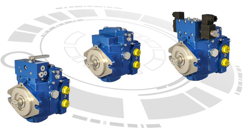
PM20 is a variable displacement, axial piston pump, with swashplate system, for closed loop hydrostatic transmissions.
It provides a continuously variable flow rate between zero and maximum in forward and reverse direction. Flow rate is proportional to rotation
speed and swashplate angle.
It can feature a charge pump to keep the circuit pressurised. This avoids risk of cavitations and ensures a good performance of the transmission.
It offers several types of control: servo mechanical, servo hydraulic, electro-proportional with or without feedback and hydraulic automotive.
It is equipped with high pressure relief valves and can be delivered with auxiliary gear pumps.
It is available in single or tandem versions.
As options, PM20 can be featured with roller bearing, customized identification plate, mechanical inching, hydraulic inching, filter on pressure line,
external connections for filter, UNF thread ports, finishing coat, fluorinated elastomer seals, flushing valve, safety valve and anti-stall valve.
PM20-21 PM20-25 PM20-28
cm³/rev 21 25 27,36
Displacement
[in³/rev.] [1.28] [1.53] [1.67]
Theoretical flow at full displacement L/min 75,6 90,0 98,5
and rated speed [GPM] [20.0] [23.8] [26.0]
Rated speed rpm 3 600
Rated pressure bar [PSI] 250 [3 625]
Max. pressure bar [PSI] 370 [5 366] *
Mounting flange SAE B
Servo mechanical, Servo hydraulic, Hydraulic automotive, Electro-proportional
Controls with and without feedback
Mass kg [lb] from 20 [44.1] to 23 [50.7]
Rotation Clockwise or Counterclockwise
* Consult your Poclain Hydraulics application engineer.
2 27/08/2021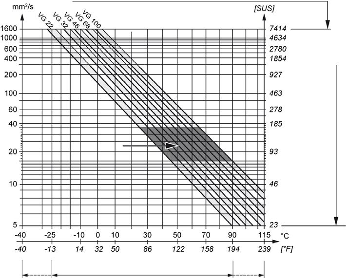
POCLAIN HYDRAULICS                                                  Variable displacement pump - PM20

                     CONTENT

                                                                                                        Model
                                                                                                        Code
                     MODEL CODE                                                    4

                     TECHNICAL SPECIFICATIONS                                      6
                     Features                                                      6
                     Main dimensions                                               7
                     Port characteristics                                          7

                                                                                                        specifications
                                                                                                          Technical
                     OPERATING PARAMETERS                                          9
                     Operating parameters                                          9
                     Charge pressure                                               9
                     Case pressure                                                 9
                     Pressure ratings                                              9
                     Speed ratings                                                 9
                     Inlet pressure                                               10
                     Theoretical output                                           10

                                                                                                        Parameters
                     Poclain Hydraulics recommandations for fluid                 10

                                                                                                         Operating
                     Fluid and filtration                                         11
                     Viscosity range                                              11

                     SYSTEM DESIGN PARAMETERS                                     12
                     Sizing equations                                             12
                     Redundant braking system requirement                         12
                     Loop flushing                                                12
                     Reservoir                                                    13

                                                                                                        System design
                     Case drain usage for tandem pump                             13

                                                                                                         Parameters
                     Differential pressure                                        13
                     Bearing life and external shaft loading                      14
                     Hydraulic unit life                                          15
                     Mounting flange loads                                        15

                     FEATURES                                                     16
                     High pressure relief valve                                   16
                     Charge relief valve                                          17
                     Charge pump                                                  18

                                                                                                            Features
                     Displacement limiters                                        19
                     By-pass                                                      19
                     Mounting flange and shafts                                   20
                     Auxiliary mounting pad                                       21
                     Tandem pumps                                                 22
                     Gear pumps                                                   23

                     CONTROLS                                                     24
                     Mechanical servo control with feedback                       24
                                                                                                            Controls

                     Hydraulic servo control                                      26
                     Hydraulic automotive control                                 28
                     Electro-proportional servo control                           30
                     Electro-proportional control with feedback                   32

                     OPTIONS                                                      33
                     Roller bearing                                               33
                     Customized identification plate                              33
                     Mechanical inching                                           33
                     Hydraulic inching                                            33
                                                                                                            Options

                     Filter on pressure line                                      34
                     External connections for filter                              35
                     UNF thread ports                                             35
                     Finishing coat                                               35
                     Fluorinated elastomer seals                                  35
                     Flushing valve                                               36
                     Safety valve                                                 37
                     Anti-stall valve                                             37
27/08/2021                                                                                              3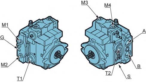
MODEL CODE
      PM20 - Variable displacement pump                                                          POCLAIN HYDRAULICS

                                                                                           MODEL
                                                                                    1        2        3         4        5

                                                                 P M 2 0

    1
    Displacement cm3/rev [in3/rev]
    21 [1.28]                           21
    25 [1.53]                           25
    27,36 [1.67]                        28

    2
    Mounting flange and shaft
            Splined shaft (z = 13; 16/32 D.P.)    S3
    SAE B Splined shaft (z = 15; 16/32 D.P.)      S4
            Shaft for secondary tandem pump       T1

    3
    Control
    Mechanical servo control with feed back                 A
    Hydraulic servo control                                 S
    Hydraulic automotive control 12V                       D12
    Hydraulic automotive control 24V                       D24
    Electro-proportional control 12V                       P12
    Electro-proportional control 24V                       P24
                                                                   4
    Electro-proportional servo control 12V with feedback   Q12
                                                                   K restrictor mm [in]
    Electro-proportional servo control 24V with feedback   Q24
                                                                   Without restrictor                          00
                                                                   Ø 0,6 [dia. 0.023]                          06
                                                                   Ø 0,7 [dia. 0.027]                          07
                                                                   Ø 0,8 [dia. 0.031]                          08
                                                                   Ø 0,9 [dia. 0.035]                          09
                                                                   Ø 1,0 [dia. 0.047]                          10

                                                                   5
                                                                   High pressure relief valve setting
                                                                   Max. system pressure (bar [PSI])
                                                                   Without valve (only check valve)                     00
                                                                   150 [2 175]                                          15
                                                                   200 [2 900]                                          20
                                                                   250 [3 625]                                          25
                                                                   300 [4 351]                                          30
                                                                   350 [5 076]                                          35
                                                                   370 [5 366] *                                        37
                                                                   * Consult your Poclain Hydraulics application engineer.

4                                                                                                              27/08/2021
POCLAIN HYDRAULICS                                                                                Variable displacement pump - PM20

CODE

                                                                                                                                      Model
                                                                                                                                      Code
 6       7        8       9         10        11

                                                                                                                                      specifications
                                                                                                                                        Technical
                                                                     11
                                                                     Options
                                                                     Without option                                          00
                                                                     Roller bearing                                         CR
                                                                     Customized identification plate                         DP
6
                                                                     Mechanical inching                                      IC
Rotation
                                                                     Hydraulic inching                                       HI
Clockwise                       R
                                                                     Filter on pressure line without clogging indicator      F0

                                                                                                                                      Parameters
                                                                                                                                       Operating
Counter clockwise               L
                                                                     Filter on pressure line with clogging indicator         F2
                                                                     External connections for filter                         F3
                                                                     UNF thread ports                                        FU
7                                                                    Finishing coat                                          PA
Charge relief valve setting bar [PSI]                                Fluorinated elastomer seals                             EV
Without charge relief valve                            00            Flushing valve                                          VS
Setting 22 [319]                                       22            Safety valve                                           VPU
                                                                     Anti-stall valve                                        SD

                                                                                                                                      System design
                                                                                                                                       Parameters
8                                                                              In case of request for a combination of several
                                                                               options, please contact your Poclain Hydraulics
Charge pump displacement cm3/rev [in3/rev]
                                                                               application engineer for further information.
Without charge pump                                00
9 [0.54]                                           08
11 [0.67] *                                        11
12 [0.73]                                          12
* Only and mandatory for Hydraulic automotive control.

                                                                                                                                          Features
9
Auxiliary mounting pad
Without auxiliary mounting pad                              S
SAE A flange (Z=9, 16/32 DP)                                A
Tandem                                                      T

10
                                                                                                                                          Controls

Gear pump cm3/rev [cu.in/rev]
Without gear pump                                               00
                                         4,5 [0.27]             04
                                         6,0 [0.37]             06
                                         8,5 [0.52]             08
SAE A flange (If digit 9 = A)            11,0 [0.67]            11
                                         14,5 [0.88]            14
                                         17,0 [1.04]            17
                                         19,5 [1.19]            20
                                                                                                                                          Options

27/08/2021                                                                                                                            5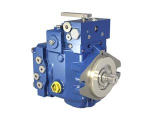
PM20 - Variable displacement pump POCLAIN HYDRAULICS
TECHNICAL SPECIFICATIONS
Features
PM20-21 PM20-25 PM20-28
cm³/rev 21 25 27,36
Displacement
[in³/rev.] [1.28] [1.53] [1.67]
Theoretical flow at full displacement and rated speed L/min 75,6 90.0 98,6
(3600 rpm) [GPM] [20.0] [23.8] [26.0]
Max. theoretical absorbed power at rated speed kW 31,5 37,5 41,1
and full displacement, p=250 bar [3 625 PSI] [hp] [42.2] [50.2] [55.1]
Theorical absorbed torque at full displacement N.m 83,6 99,5 109,0
p=250 bar [3 625 PSI] [in.lbf] [740] [881] [965]
kg.m²
Moment of inertia 0.0013 [0.0009]
[slug.ft²]
3
cm /rev
Internal charge pump 9,1 [0.55] or 12 [0.73] or 11 [0.67] for automotive
[in3/rev]
bar
Charge relief valve setting 22 [319]
[PSI]
bar
High pressure relief valve setting max. 370 [5 366] *
[PSI]
Mounting flange SAE B
20 [44.1] with control S
Mass kg [lb]
23 [50.7] with controls A, D, P, Q
* Consult your Poclain Hydraulics application engineer.
6 27/08/2021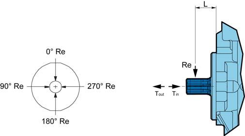
POCLAIN HYDRAULICS Variable displacement pump - PM20
Main dimensions
PM20 with hydraulic servo control and without auxiliary mounting pad.
Model
Code
1 2 3 4 5 6 7 8 9 10 11
P M 2 0 S S
9,7 -0,1
0
0
[0.38 -0.004 ] 84 [3.31] 87 [3.43]
specifications
Clockwise (R)
Technical
122,1 [4.81]
25,5 [1.00]
100 [3.94]
85 [3.35]
207,2 [8.16]
23 [0.91]
85,1 [3.35]
25,5 [1.00]
Parameters
Operating
87 [3.43]
131,5 [5.18] 146 [5.75]
Counter
145 [5.71] clockwise (L) 174 [6.85]
151 [5.94]
System design
Parameters
71,5 [2.81] 71 [2.79]
See from page 18 to page 32
100 [3.94]
171 [6.73]
for control dimensions.
Features
93,5 [3.68]
Port characteristics
Controls
M3
M4
G1
ISO 1179-1 ISO 11926-1
Port Function
M1 (standard) (option FU)
A A-B Services 3/4” GAS 1-1/16-12 UNF-2B
G2 G1 Auxiliary 1/4” GAS 9/16-18 UNF-2B
M1/M2 Gauge 1/4” GAS 9/16-18 UNF-2B
M3/M4 Servo control pilot 1/8” GAS 7/16-20 UNF-2B
S Suction 3/4” GAS 1-1/16-12 UNF-2B
M2
Options
B T1 Drain 1/2” GAS 1/2” GAS
T2 T2 Drain 1/2” GAS 7/8-14 UNF-2B
T1 S
G2 Auxiliary 3/8” GAS 3/8” GAS
27/08/2021 7
PM20 - Variable displacement pump   POCLAIN HYDRAULICS

8                                                 27/08/2021
POCLAIN HYDRAULICS                                                                                        Variable displacement pump - PM20

               OPERATING PARAMETERS

                                                                                                                                              Model
                                                                                                                                              Code
Operating parameters

                                                                    PM20-20                      PM20-25                       PM20-28
               Minimum                                                                              700
Speed
               Max. without load            min-1(rpm)                                             3 900
ratings
               Max. with load                                                                      3 600

                                                                                                                                              specifications
               Rated                                                                           250 [3 625]

                                                                                                                                                Technical
System
               Maximum                      bar [PSI]                                          370 [5 366] *
pressure
               Minimum low loop                                                                  10 [145]
Inlet          Mini continuous              bar (abs.)                                           0,8 [11.6]
pressure                                    [PSI abs.]                                           0,5 [7.2]
               Mini (cold start)
Case           Continuous                                                                        1,5 [21.7]
                                            bar [PSI]
pressure       Maximum (cold start)                                                              2,5 [36.2]
               Standard version                                                                  22 [319]

                                                                                                                                              Parameters
Charge                                      bar [PSI]

                                                                                                                                               Operating
pressure       Max. charge pressure                                                              30 [435]
Servo case
               Maximum                      bar [PSI]                                            30 [435]
pressure
                                                                           * Consult your Poclain Hydraulics application engineer.

Charge pressure

                                                                                                                                              System design
A charge flow is required to maintain a positive pressure in the low pressure loop of a closed loop hydrostatic transmission. Charge

                                                                                                                                               Parameters
pressure ensures proper lubrication and rotating group operation. It is recommended to maintain the charge pressure at a minimum of
6 bar [87 psi] above case pressure. For more details, refer to charge pump paragraph, page 18.

Case pressure
Case pressure must be maintained within the limits shown in the table ''Operating parameters''. Ensure housing is always filled with
hydraulic fluid, especially during start-up of the machine.

Pressure ratings
Maximum peak pressure

                                                                                                                                                  Features
It is the maximum allowable pressure. It is equivalent to the maximum setting of the maximum high pressure relief valve. A self-propelled
machine can reach the maximum peak pressure value no more than 1-2% of that work cycle.

Work cycle
A fundamental factor for ensuring correct hydrostatic transmission sizing is the machine work cycle (pressure-time ratio, seasonality,
pressure vs. percentage of time at max. displacement, machine type). Part service life depends on the correct choice in relation to the
work cycle.

Overloads
It is mandatory to protect parts against any possible overloads.
                                                                                                                                                  Controls

Speed ratings

The table ''Operating parameters'' gives minimum and maximum rated speeds. Note that all displacements might operate under different
speed limits. Definitions of these speed limits appear below.

Maximum speed is the highest operating speed allowed. Over speeding reduces pump life time, can lead to loss of hydrostatic power and
braking capacity. Never exceed the maximum speed limit under any operating conditions.
                                                                                                                                                  Options

Nominal speed is the speed offering the maximal efficiency.

27/08/2021                                                                                                                                    9
PM20 - Variable displacement pump POCLAIN HYDRAULICS
Inlet pressure
Charge pump inlet pressure is key for acceptable pump life and performances. A continuous inlet pressure of not less than 0,8 bar abs. [11.6
PSI abs.] is recommended. An continuous inlet pressure less than 0.5 bar abs. [7.2 PSI abs.] indicates inadequate inlet design or a restricted
filter. Pressures less than 0.5 bar abs. [7.2 PSI abs.] can happen at cold start, but should increase with oil temperature.
Theoretical output
Theoretical output flow is a function of pump displacement and speed. It is relevant to size the rest of the circuit. Theoretical flow does not take
into account losses due to leakage or variations in displacement. Refer to performances, page 6, for volumetric and overall efficiencies at
various operating speeds and pressures.
Poclain Hydraulics recommandations for fluid
Poclain hydraulics recommends the use of hydraulic fluids defined by the ISO 15380 and ISO 6743-4 standards.
For temperate climates, the following types are recommended.
• HM 46 or HM 68 for fixed installations.
• HV 46 or HV 68 for mobile installations.
• HEES 46 for mobile installations.
These specifications correspond to category 91H of the CETOP standard, parts 1, 2 and 3 of the DIN 51524 standard,
and grades VG32, VG 46 and VG68 of the ISO 6743-4 standards.
It is also possible to use ATF, HD, HFB, HFC or HFD type hydraulic fluid upon Poclain Hydraulics specific approval of the
components’ operating conditions.
Standardized designations for the fluids
• HM : Mineral fluids having specific antioxidant, anticorrosion and antiwear properties (HLP equivalent to DIN 51524
parts 1 and 2).
• HV : HM mineral fluids providing improved temperature and viscosity properties (DIN 51524 part 3).
• HEES :Biodegradable fluids based on organic esters.
It is also possible to use a fluid that meets the biodegradability criteria and is compatible in the event of
accidental food contact. The BIOHYDRAN FG 46 fluid designed by the company Total has undergone testing of
its properties and performance on our test benches. Since this type of fluid has not yet been categorized, it is the
responsibility of machine manufacturers to validate its compatibility with all of the components used in order to
guarantee that the intended functions will be fulfilled and this for the desired life time of all equipment items.
For biodegradable fluids, consult your Poclain Hydraulics’ application engineer
During operation, the temperature of the oil must be between 0°C [32°F] and 80°C [176°F]; the minimum and
maximum temperatures may be exceeded momentarily by ± 20°C [ +68°/-4° F] for a duration of less than 30
minutes.
For all applications outside these limits, please consult with your Poclain Hydraulics’ application engineer.
Pump storage
If the pump remains on stock for more than 6 months, a status verification must be performed before you install it on a
machine. Pay attention to sealing condition, rust presence and free rotation of shaft.
10 27/08/2021POCLAIN HYDRAULICS Variable displacement pump - PM20
Fluid and filtration
The contaminating particles suspended in the hydraulic fluid cause the hydraulic mechanisms moving part wear. On hydraulic pumps,
Model
Code
these parts operate with very small dimensional tolerances. In order to reach the part life, it is recommended to use a filter that maintains
the hydraulic fluid contamination class at a max. of:
9 according to NAS 1638
22/18/13 according to ISO 4406:1999
According to the type of application decided for the pump, it is necessary to use filtration elements with a filtration ratio of:
specifications
β 20 to 30 ≥ 100
Technical
Making sure that this ratio does not worsen together with the increasing of the filter cartridge differential pressure.
If these values cannot be observed, the component life will consequently be reduced and it is recommended to contact the Poclain
Hydraulics Customer Service.
Filters on charge circuit
Filters on the charge circuit (F0-F2) are designed without by-pass. The max. pressure drop on the filtration part must not exceed 2 bar [29
PSI] (3 bar [43.5 PSI] in case of cold starting) at pump full rating. To monitor the pressure drop, It is recommended to use the clogging
indicator on the filtration element (F2 option). Contact your Poclain Hydraulics Application engineer, each time the pump is not charged by
Parameters
Operating
its internal charge pump.
Filters on charge circuit are mounted on the pump special support.
Filters assembling
The suction filter is mounted on the suction line. Check that the pressure before the charge pump is 0.8 bar abs. [11.6 PSI abs.], measured
on the pump suction port (0.5 bar [7.2 PSI] for cold starting).
Viscosity range
System design
Parameters
For both max. efficiency and life of the unit, the operative viscosity should be chosen within the optimum range of:
√opt = optimum operating viscosity from 16 to 36 mm2/s [from 74.1 to 166.8 SUS] referred to the closed loop temperature.
Working conditions: the following limits of viscosity apply
√min = 5 mm2/s [23 SUS] short-duration at a max. permissible leakage oil temperature of 90° C [194°F]
√max = 1000 mm2/s [4 634 SUS] short-duration, on cold start.
For brief instants during the cold starting
Features
For brief instants with leakage oil at 90°C
Controls
Optimum
viscosity
Options
Hydraulic fluid temperature range
Ensure fluid temperature and viscosity limits
are concurrently satisfied.
27/08/2021 11PM20 - Variable displacement pump POCLAIN HYDRAULICS
SYSTEM DESIGN PARAMETERS
Consult your Poclain Hydraulics application engineer to validate your
design parameters before using the pump in your application.
Sizing equations
The following equations are helpful when sizing hydraulic pumps. Generally, the sizing process is initiated by an evaluation of the machine
system to determine the required motor speed and torque to perform the necessary work function. First, the motor is sized to transmit the
maximum required torque. The pump is then selected as a flow source to achieve the maximum motor speed.
Vg.n.v
Output flow Q = (l/min)
1000
Vg.p
SI units Input torque M = (N.m)
20..m
M. n. Q.p
Input power P = = (kW) Vg=Displacement per revolution cm3/tr [in3/rev]
30 000 600.t
p = po - pi (system pressure) bar [PSI]
n = Speed min-1 [rpm]
Vg.n.v v = Volumetric efficiency
Output flow Q = [GPM] m = Mechanical efficiency
231
t = Overall efficiency = v x m
Vg.p
US units Input torque M =
2..m
[lbf.in]
M.n. Q.p
Input power P = = [hp]
198 000 1714.t
Redundant braking system requirement
Unintended vehicle or machine movement hazard.
The loss of hydrostatic drive line power, in any mode of operation (forward, neutral, or reverse)
may cause the system to lose hydrostatic braking capacity. You must provide a braking system,
redundant to the hydrostatic transmission, sufficient to stop and hold the vehicle or machine in
the event of hydrostatic drive power loss.
Loop flushing
Closed circuit may require a flushing valve to meet temperature and cleanliness requirements. A flushing valve takes a part of hot fluid flow from
the low pressure loop of the system loop for cooling and filtering. Make sure that the charge pump provides adequate flow for the flushing valve
flushing and the flushing valve does not cause charge pressure to drop below recommended limits.
See option VS for
more information
12 27/08/2021POCLAIN HYDRAULICS Variable displacement pump - PM20
Reservoir
Model
Code
The reservoir provides clean fluid, dissipates heat, and removes entrained air from the hydraulic fluid. It allows for fluid volume changes
associated with fluid expansion and cylinder differential volumes. Minimum reservoir capacity depends on the volume needed to perform these
functions. Typically, a capacity of one half the charge pump flow (per minute) is satisfactory for a closed reservoir. Open circuit systems sharing
a common reservoir require greater fluid capacity.
Locate the reservoir outlet (suction line) near the bottom, allowing clearance for settling foreign particles. Use a 100 - 125 μm screen covering the
outlet port.
specifications
Place the reservoir inlet (return lines) below the lowest expected fluid level, as far away from the outlet as possible.
Technical
Use a baffle (or baffles) between the reservoir inlet and outlet ports to promote de-aeration and reduce fluid surging.
Case drain usage for tandem pump
On tandem pumps, and to ensure lubrification of both pumps, excess flow from the first pump charge relief valve must be routed into the
housing of the second pump and viceversa.
Parameters
Operating
G2-2
M1-1 G1-1 R-1 M2-1 A-1 M3-2M4-2 M1-2 G1-2 R-2 M2-2 A-2
M3-1
M4-1
System design
Parameters
T B-1 S B-2
Differential pressure
The differential pressure is the High pressure relief valve setting minus Charge relief valve setting.
Features
High pressure relief Max. system
valve setting = pressure
Differential pressure
Controls
Charge relief valve
setting
Options
27/08/2021 13PM20 - Variable displacement pump POCLAIN HYDRAULICS
Bearing life and external shaft loading
Bearing life:
Bearing life is a function of speed, pressure, swashplate angle and external loads. Oil type and viscosity impact bearing life.
PM20-28
Bearing life (B10 hours) 19 965
Normal bearing life in B10 hours is shown in the table above. Figures have been calculated under the following operating conditions :
A continuous differential pressure of 120 bar [1740 PSI], 1800 rpm shaft speed, 22 bar [290 PSI] charge pressure, maximum displacement,
without any external shaft side load. The data is based on a 50% forward, 50% reverse duty cycle, and standard charge pump size.
Shaft Loads
PM20 pumps are designed with bearings that can accept external radial and thrust loads. The external radial shaft load limits depend on the
load position, orientation, and operating conditions of the unit.
The maximum permissible radial load (Re), is based on the maximum external moment (Me), and the distance (L) from the mounting
flange to the load. It may be determined using the table and formula below. Thrust (axial) load limits are also shown.
Re = Me / L
All external shaft loads affect bearing life. In applications with external shaft loads, minimize the impact by positioning the load at 90° or 270° as
shown in the figure.
Contact your Poclain Hydraulics representative for an evaluation of unit bearing life if:
• Continuously applied external loads exceed 25 % of the maximum allowable radial load Re.
• The pump swashplate is positioned on one side of center all or most of the time.
• The unit bearing life (B10) is critical.
External moment (Me) Maximum shaft thrust in (Tin)
N.m [in.lbf] N [lbf]
PM20-28 44 [389] 1 000 [224.8]
at 120 bar [1 740 PSI] and 3 600 rpm
Radial and thrust load position
End view of
shaft
Axis of swashplate
rotation
For an accurate calculation, consult your Poclain Hydraulics
application engineer and use new AXEL program.
14 27/08/2021POCLAIN HYDRAULICS Variable displacement pump - PM20
Hydraulic unit life
Model
Code
Hydraulic unit life is the life expectancy of the hydraulic components. It depends on speed and system pressure even if , system pressure
is the dominant operating variable. High pressure, generated by high load, reduces hydraulic unit life.
Design the hydraulic system according to the expected machine duty cycle. Take in consideration the expected percentages of time at
various loads and speeds. Ask your Poclain Hydraulics representative to calculate an appropriate pressure based your hydraulic system
design. If duty cycle data is not available, input power and pump displacement are used to calculate system pressure.
All pressure limits are differential pressures (referenced to charge pressure) , taking a normal charge pressure in consideration.
specifications
PM20 pumps will meet satisfactory life expectancy if applied within the parameters specified in this technical documentation. For more
Technical
detailed information on hydraulic unit life see Operating Parameters in page 9.
Mounting flange loads
Adding tandem mounted pumps, and/or tandem auxiliary pump(s), subjecting pumps to shock loads may generate excessive loads on the
front mounting flange. The overhung load moment for multiple pump mounting can be estimated as shown in the figure below.
Overhung load example
CG Auxiliary pad
CG
Parameters
Operating
Mounting flange pump 1 pump 2
System design
Parameters
L1
L2
Estimating overhung load moments
W = Weight of pump (kg)
L = Distance from mounting flange to pump center of gravity (CG)
MR = GR (W1L1 + W2L2 + ... + WnLn)
Features
MS = GS (W1L1 + W2L2 + ... + WnLn)
Where:
MR = Rated load moment (N.m)
MS = Shock load moment (N.m)
GR*= Rated (vibratory) acceleration (G’s) (m/sec²)
GS*= Maximum shock acceleration (G’s) (m/sec²)
* Calculations will be carried out by multiplying the gravity (g = 9.81 m/sec²) with a given factor. This factor depends on the application.
Allowable overhung load moment are shown in the below table. Exceeding these values requires additional pump support.
Controls
Rated moment (MR) Shock load moment (MS)
N.m [in.lbf] N.m [in.lbf]
PM20-20 370 [3 274] 600 [5 310]
PM20-25 370 [3 274] 600 [5 310]
PM20-28 370 [3 274] 600 [5 310]
For an accurate calculation, consult your Poclain Hydraulics
Options
application engineer.
27/08/2021 15PM20 - Variable displacement pump POCLAIN HYDRAULICS
FEATURES
High pressure relief valve
The High pressure relief valves maintain circuit pressure in the proper range. The check valves allow charge flow to replenish the low pressure
loop of the circuit. The high pressure relief valves ensure a high pressure protection of the high pressure loop of the circuit.
High pressure relief valves are available in a wide range of settings.
When high pressure relief valves are not desired, pumps is equipped with charge circuit check valves only. The High pressure relief valve are
not adjustable. To change setting is necessary to change the whole valve.
High pressure relief valves are intended for transient overpressure protection and are not
intended for continuous pressure control. Flow over relief valves for extended periods of time
may result in severe heat build up. High flows over relief valves may result in pressure levels
exceeding the nominal valve setting and potential damage to system components.
1 2 3 4 5 6 7 8 9 10 11
P M 2 0
High pressure Available setting
relief valve bar [PSI] M3 M4 G A M1
Without - 00
150 [2 175] 15
200 [2 900] 20
250 [3 625] 25
With BH
300 [4 351] 30
350 [5 076] 35
Rs3
370 [5 366] * 37
* Consult your Poclain Hydraulics application engineer.
T2 S B M2
T1
ISO VG46 hydraulic fluid at 50°C [122°F]
bar PSI
400 5 801
300 4 351
Pressure
200 2 900 High pressure
relief valve
100 1 450
The high pressure relief valve setting is not the
0 25 50 75 100 L/min differential pressure between A and B ports
6.6 13.2 19.8 26.4 GPM
Flow
16 27/08/2021POCLAIN HYDRAULICS Variable displacement pump - PM20
Charge relief valve
Model
Code
The charge pressure relief valve provides a relief outlet for charge circuit. This valve is used to set the charge pressure of the circuit. Flow
through the valve is ported to case.
The nominal charge relief setting is referenced to case pressure.
Incorrect charge pressure settings may result in the inability to build
required system pressure and/or inadequate loop flushing flows.
Ensure correct charge pressure under all conditions of operation to
maintain pump control performance.
specifications
Technical
1 2 3 4 5 6 7 8 9 10 11
P M 2 0
Parameters
Operating
Charge relief Available setting
valve bar [PSI] M3 M4 G A M1
Without - 00
With 22 [319] 22
System design
Parameters
BH
Rs3
T2 S B M2
T1
bar
ISO VG46 hydraulic fluid at 50°C [122°F]
PSI Features
30 435 Charge relief valve
Pressure difference
25 362.6
Controls
20 290
15 217.5
10 145
5 72.5
0 0
500 1000 1500 2000 2500 3000
Options
Pump speed (rpm)
27/08/2021 17PM20 - Variable displacement pump POCLAIN HYDRAULICS
Charge pump
Charge flow is required on all PM20 pumps used in closed circuit installations. The charge pump provides flow to make up internal leakage,
maintain a positive pressure in the main circuit, provide flow for cooling and filtration, replace any leakage losses from external valving or
auxiliary systems, and to provide flow and pressure for the control system.
Many factors influence the charge flow requirements. These factors include system pressure, pump speed, pump swashplate angle, type of
fluid, temperature, size of heat exchanger, length and size of hydraulic lines, control response characteristics, auxiliary flow requirements,
hydrostatic motor type, etc.
Unusual application conditions may require a more detailed review of charge pump sizing. Charge pressure must be maintained at a specified
level under all operating conditions to prevent damage to the transmission. Poclain Hydraulics recommends testing under actual operating
conditions to verify this.
M3 M4 G A M1
BH
Rs3
T2 S B M2
T1
Charge pump sizing/selection
In most applications, a general guideline is that the charge pump displacement should be at least 20% of the main pump displacement.
1 2 3 4 5 6 7 8 9 10 11
P M 2 0
Displacement
Charge pump
cm³/rev [in³/rev]
Without - 00
9 [0.55] 08
With 11 [0.67] * 11
12 [0.73] 12
* Only and mandatory for PM20 hydraulic automotive control.
Pump without internal charge pump is also available. In this case an external flow must provide charge pressure and charge flow in order to assure
the requested pump performance.
Contact your Poclain Hydraulics application engineer for more
information.
Pump version without internal charge pump is available. In this case
an external flow must provide charge pressure and charge flow in order
to assure the requested pump performance.
18 27/08/2021POCLAIN HYDRAULICS Variable displacement pump - PM20
Displacement limiters
Model
Code
PM20 are designed with mechanical displacement (stroke) limiters. You can limit maximum displacement of the pump to a certain per-
cent of its maximum displacement to near zero in both direction.
The displacement limiters are located on the both sides of the servo piston and are adjustable by screw.
Take care in adjusting displacement limiters to avoid an undesirable condition of output flow
or speed. Retorque the sealing lock nut after every adjustment to prevent an unexpected
change in output conditions and to prevent external leakage during pump operation.
specifications
Technical
Max. displacement
adjustement
Neutral position
adjustement
Parameters
Operating
System design
Parameters
By-pass
PM20 features a by-pass function. By-passing Port A and Port B is achieved by unscrewing a screw located on the cover. The by-pass
connect the ports A-B and must be use only in emergency case and only for short movement.
M3 M4 G A M1
Features
By-pass screw
(unscrew max. 2 turns) BH
Rs3
T2 S B M2
T1
Controls
To avoid leakage, do not exceed two turns of the screw.
By-pass valve is intended for moving a machine for very short
distances at very slow speeds. It is not intended as tow valve.
Options
27/08/2021 19PM20 - Variable displacement pump POCLAIN HYDRAULICS
Mounting flange and shafts
SAE B- Splined shaft
1 2 3 4 5 6 7 8 9 10 11
P M 2 0
S3 13 teeth; Max torque: 220 N.m [1 947 in.lbf]
30,9
[1.22]
Splined ANSI B92.1a-1996
Pitch 16/32” DP
-0.002 ]
M6
Pressure angle 30°
Ø 101,6 -0.054
[dia. 4.00 +0
+0
Tolerance class: 5
14 [0.55]
20 [0.79]
0
9,7 -0,1
0
40,6 [0.38 -0.004 ]
[1.59]
S4 15 teeth; Max torque: 360 N.m [3 186 in.lbf]
38
[1.50]
]
Splined ANSI B92.1a-1996
-0.002
Ø 101,6 -0.054
M8
[dia. 4.00 +0
Pitch 16/32” DP
+0
Pressure angle 30°
Tolerance class: 5
19 [0.75]
25 [0.98]
0
9,7 -0,1
0
46 [0.38 -0.004 ]
[1.81]
T Shaft for secondary tandem pump
20 27/08/2021POCLAIN HYDRAULICS Variable displacement pump - PM20
Auxiliary mounting pad
Model
Code
SAE A flange
Max. Torque: 80 N.m [708 in.lbf]
1 2 3 4 5 6 7 8 9 10 11
P M 2 0 A
specifications
Technical
00 Without charge pump
09 With charge pump: 9,0 cm3/rev [0.54 in3/rev]
11 With charge pump: 11,0 cm3/rev [0.67 in3/rev] *
12 With charge pump: 12,0 cm3/rev [0.73 in3/rev]
Parameters
Operating
* Only and mandatory for PM20 hydraulic automotive control.
33,5
[1.32]
System design
20
Parameters
[0.79]
Ø 106,4 [dia. 4.19]
4 x M10
130,4 [5.13]
+0.001 ]
Features
[dia. 3.25 +0.003
8 [0.31]
Ø 82,55 +0.071
+0.036
35 [1.38]
201 [7.91]
Splined ANSI B92.1a-1996
Pitch 16/32” DP
Pressure angle 30°
9 teeth
Tolerance class: 5
Controls
Do not rotate the auxilliary mounting pad cover.
Options
27/08/2021 21PM20 - Variable displacement pump POCLAIN HYDRAULICS
Tandem pumps
Max. torque intermediate coupling
200 N.m [1 770 in.lbf]
Front axial Rear axial Next pump
pump pump
Me1 for the first pump
Me imput torque Me2 for the second pump
Me3 for the next pump
Torque required by auxiliary pumps is additive.
Ensure requirements don’t exceed shaft torque ratings.
1 2 3 4 5 6 7 8 9 10 11
Front axial
pump P M 2 0 00 T
Rear axial
+
pump P M 2 0 T1
Number of charge pump Axial Mounting flange Charge Auxiliary mounting
in the tandem pump and shaft pump flange
SAE B; 13 teeth S3
Front Without 00 Tandem fitting T
SAE B; 15 teeth S4
0 charge pump Shaft for SAE A flange A
Rear secondary T1 Without 00 Without auxiliary
tandem pump S
mounting pad
SAE B; 13 teeth S3
Front Without 00 Tandem fitting T
SAE B; 15 teeth S4
1 charge pump * Shaft for 08 SAE A flange A
Rear secondary T1 With or Without auxiliary
tandem pump 12 S
mounting pad
Ports T and G of the first pump must be
* The charge pump can only be located on the rear axial pump. connected with ports T and G of the
second pump.
* Auxiliary mounting flange S with charge pump is done
Tandem pumps are not available for
closing SAE A by a steel cover. When SAE B will be available a
tandem pump could be composed by 2 single = PM10. hydraulic automotive control.
22 27/08/2021POCLAIN HYDRAULICS Variable displacement pump - PM20
Gear pumps
1 2 3 4 5 6 7 8 9 10 11
Model
Code
P M 2 0
Auxiliary mounting pad
Gear pump
Displacement Pressure Dimension Mass Efficiency
Continuous Max.
specifications
max. intermittent Max. peak
pressure pressure pressure A B C
Technical
cm3/rev bar bar bar mm mm mm kg %
[cu.in/rev] [PSI] [PSI] [PSI] [in] [in] [in] [lb]
SAE A 4 250 270 290 93,0 2,30
04
[0.24] [3 625] [3 915] [4 205] [3.66] [5.07]
6,0 250 270 290 96,3 2,45
06
[0.37] [3 625] [3 915] [4 205] [3.68] [5.40]
8,5 250 270 290 100,5 2,60
08
[0.52] [3 625] [3 915] [4 205] [3.96] [5.73]
11,0 250 270 290 104,6 106,4 82,5 2,70
A 11 95 *
Parameters
[0.67] [3 625] [3 915] [4 205] [4.12] [4.19] [3.25] [5.95]
Operating
14 250 270 290 109,6 2,80
14
[0.85] [3 625] [3 915] [4 205] [4.21] [6.17]
16,5 230 240 250 113,8 2,95
17
[1.01] [3 335] [3 480] [3 625] [4.37] [6.51]
19,5 210 220 230 118,8 3,10
20
[1.19] [3 045] [3 190] [3 335] [4.68] [6.84]
* Value collected during
System design
Gear pumps are always delivered flanged on the axial pump. They can not be sold alone. the testing at 1500 rpm.
Parameters
Features
Controls
Options
27/08/2021 23PM20 - Variable displacement pump POCLAIN HYDRAULICS
CONTROLS
Mechanical servo control with feedback
1 2 3 4 5 6 7 8 9 10 11
P M 2 0 A
The variation in pump displacement is reached by control lever rotation to adjust hydraulic servo piston position. Control
Control function
lever range is 34°. Movement of control lever is independent of the pressure and pump speed.
To avoid sudden accelerations and stoppages, two restrictors (Rs1 and Rs2) are inserted between servo control and
Control regulation
hydraulic servo piston. They are used to regulate control shifting speed.
The feedback system between swash plate and hydraulic servo piston permit to maintain costant displacement of the
Feedback function pump if the pressure between pump and hydraulic motor changes.
The feedback function is reached by a lever that connects the swashplate and the hydraulic servo piston.
Rs1 Rs2
Flow rate determination
G R M1 A
Rotation Pressure Output Input
M3
Y A B
Clockwise (R) M4
X B A
Y B A BH
Counter clockwise (L)
X A B
T1 T2 M2 B
X
34°
Control lever torque vs.
N.m Control lever rotation
34°
[in.lbf]
Y
2 17.7
1 8.8
0 0
-1 -8.8
-2 -17.7
-30 -20 -10 0 10 20 30
Control shaft rotation (degrees)
The spring return feature in the control unit is not a safety device.
To prevent damage to the control A a positive mechanical stop must be
provided for the control A linkage.
24 27/08/2021POCLAIN HYDRAULICS Variable displacement pump - PM20
Dimensions with control A
Model
Code
8 [0.32]
54 [2.13]
35,5 [1.39]
147,9 [5.83]
134 [5.28]
specifications
99 [3.89]
Technical
233 [9.17]
Parameters
Operating
X
34°
System design
Parameters
See page 7 for other dimensions
and port characteristics.
34°
Y
58 [2.28]
103 [4.06] 15 [0.59]
Features
Controls
Options
27/08/2021 25PM20 - Variable displacement pump POCLAIN HYDRAULICS
Hydraulic servo control
1 2 3 4 5 6 7 8 9 10 11
P M 2 0 S
The variation in pump displacement is reached by pressure adjustment on the M3 and M4 servo control ports. These
ports are controlled by hydraulic proportional joystick (containing pressure reduction valves).
Control function
The joystick supply can by obtained by taking pressure from the auxiliary pump (R connection). Basic joystick can be
provided upon request.
The servo control response time can be adjusted by two restrictors (Rs1 and Rs2) inserted on the joystick supply line
(from 0,6 to1,2 mm [from 0.02 to 0.05 in]). The servo control operation pressure curve in both control directions goes
Control regulation from 4,5 to 15 bar [from 65 to 218 PSI].
The adjustment curve of the hydraulic control system has to be wider, from 4 to 16 bar [from 58 to 232 PSI].
M3 M4 G A M1
Flow rate determination
Rotation Pressure Output Input
BH
M3 B A
Clockwise (R)
M4 A B
M3 A B
Counter clockwise (L)
M4 B A
T2 S B M2
T1
Servo pressure vs. Displacement
bar [PSI]
20 290
15 217.5
10 145
5 72.5
0 50 100
Pump displacement (%)
Other curves can be used in relation to valve plate timing. Contact
your Poclain Hydraulics application engineer for furhter info.
For the selection of the regulation curve (with or without step) of the
Joystick contact your Poclain Hydraulics application engineer.
The back pressure of the return line of the joystick and the drive line
of the pump have an influence on these values.
The spring return feature in control is not a safety device.
26 27/08/202127/08/2021
100 [3.94]
100 [3.94] 85 [3.35]
POCLAIN HYDRAULICS
Dimensions with control S
93,5 [3.68]
171 [6.73]
207,2 [8.16]
122,1 [4.81]
and port characteristics.
See page 7 for other dimensions
Variable displacement pump - PM20
27
System design Operating Technical Model
Options Controls Features
Parameters Parameters specifications CodePM20 - Variable displacement pump POCLAIN HYDRAULICS
Hydraulic automotive control
1 2 3 4 5 6 7 8 9 10 11
P M 2 0 D
The variation in pump displacement is reached by continuous electro-hydraulic valve
adjustment. The adjustment is precised by pilot pressure controlled by solenoid control. The Supply
Control function pilot pressure increases proportionally to the rotation of the pump. The pump displacement voltage
increases corresponding to the higher pilot pressure. 12V D12
In case the engine is overloaded, the rotation rate decreases and the pilot pressure is reduced 24V D24
Control regulation causing a pump displacement reduction with a corresponding drop in absorbed power.
Inching function is reached by reduction of the pilot pressure, independently of the pump
Inching function
rotation speed. Consequently the pump displacement is reduced.
M1 G2 R G1 D
Flow rate determination
Rotation Pressure Output Input
EV1 B A
Clockwise (R)
EV2 A B
EV1 A B
Counter clockwise (L)
EV2 B A
A
M3 Rs1 Rs2
M4
BH
B
T2 S
It is mandatory to use 11 cc/rev charge pump, for any clarification or
details contact your Poclain Hydraulics application engineer.
28 27/08/2021POCLAIN HYDRAULICS Variable displacement pump - PM20
Dimensions with control D
Model
Code
224,6 [8.84]
212 [8.35]
Rs1 Rs2
EV1 EV2
149,2 [5.87]
118 [4.65]
specifications
Technical
M3 134,7 [5.30]
Parameters
Operating
[1.97] [1.97]
50
See page 7 for other dimensions
50
System design
and page 6 for port characteristics.
Parameters
M4
93,5 [3.68]
Solenoids specification
Operating voltage 12 VDC 24 VDC
Current 1500 mA 750 mA
Features
Resistance
5,3 ± 5% 21,2 ± 5%
at 20°C [68°F]
Deutsch DT04-2P / AMP Junior
Connector type
timer / EN 175301
Protection IP69K / IP67 / IP67 Controls
Options
27/08/2021 29PM20 - Variable displacement pump POCLAIN HYDRAULICS
Electro-proportional servo control
1 2 3 4 5 6 7 8 9 10 11
P M 2 0 P
Control function The variation in pump displacement is reached by current adjustment applied to proportional valve Supply
coils. The coils then adjust the pressure of the servo control connected to the hydraulic servo voltage
piston. The flow rate direction depends on activated coil.
12V P12
Control The reaction time can be controlled by ramps installed on the card and by restrictors (Rs1 and Rs2)
regulation positioned between the electrovalves and the hydraulic servo piston. 24V P24
Flow rate determination EP1 EP2
Rotation Control Output Input
EP1 B A
Clockwise (R) G R A M1
EP2 A B
EP1 A B Rs1 Rs2
Counter clockwise (L) M3
EP2 B A
M4
BH
Valve plate timing and regulation curve
of proportional valve influence the flow.
Contact your Poclain Hydraulics application
engineer for further info.
T2 S B M2
Solenoids specification T1
Operating voltage 12 VDC 24 VDC
Current 1500 mA 750 mA
Resistance
5,3 ± 5% 21,2 ± 5% Electrovalve current vs Displacement
at 20°C [68°F]
Connector type AMP Junior / Deutsch DT04-2P 1170 585
Protection IP6K6 / IPX9K
Current (mA) (12V)
Current (mA) (24V)
The current must not exceed 1500 mA under
12V and 800 mA under 24V.
600 150
0 50 100
Pump displacement (%)
(no load in closed loop)
30 27/08/2021POCLAIN HYDRAULICS Variable displacement pump - PM20
Dimensions with control P
Model
Code
EP1 EP2
155 [6.10]
118 [4.65]
specifications
Technical
93,5 [3.68]
Parameters
Operating
M3
Rs1
[1.97]
50
See page 9 for other dimensions
and page 8 for port characteristics.
[1.97]
50
System design
Parameters
Rs2
M4
Features
Controls
Options
27/08/2021 31PM20 - Variable displacement pump POCLAIN HYDRAULICS
Electro-proportional control with feedback
1 2 3 4 5 6 7 8 9 10 11
P M 2 0
The variation in pump displacement is reached by current adjustment applied to electro-proportional
Control function coils. The coils then adjust the pressure of the servo control. The flow rate direction depends on Supply
activated coil. voltage
Control The reaction time can be controlled by ramps installed on the card and by restrictors (Rs1 and Rs2) 12V Q12
regulation inserted between the servo control and the hydraulic servo piston.
24V Q24
The feedback function is reached by a lever that connects the swashplate and the hydraulic servo
Feedback piston. To avoid sudden accelerations and stoppages, two restrictors (Rs1 and Rs2) are inserted
function between the servo control and the hydraulic servo piston.
Flow rate determination
Rotation Control Output Input
EP1 B A
Clockwise (R) G1 R M1 A
EP2 A B
EP1 A B
Counter clockwise (L)
EP2 B A Rs1 Rs2
M3
M4
BH
T2 T1 S M2 B
50,9 113,6 [4.47] 113,6 [4.47]
[2.00]
155,8 [6.13]
144,7 [5.70]
Electrovalve current vs Displacement
1370 685
Current (mA) (12V)
Current (mA) (24V)
154 [6.09]
660 165
0 50 100
Pump displacement (%)
Type of connector: Standard DIN 43650 on request Deutsch (no load in closed loop)
32 27/08/2021POCLAIN HYDRAULICS Variable displacement pump - PM20
OPTIONS
Model
Code
Roller bearing
1 2 3 4 5 6 7 8 9 10 11
P M 2 0 CR
The PM20 can be provided with high capacity roller bearing to extend lifetime of the application. According to characteristics of shaft load,
the duty cycle and lifetime epectancy a roller bearing might be needed.
specifications
Technical
Consult your Poclain Hydraulics application engineer for
the application of this option.
Customized identification plate
1 2 3 4 5 6 7 8 9 10 11
P M 2 0 DP
It is possible to provide our products with dedicated plate (your part number engraved on the plate) when requested.
Parameters
Operating
This option is available only for minimum volume of 50 pieces.
Consult your Poclain Hydraulics application engineer for other
possibilities.
System design
Parameters
Mechanical inching
3
1 2 D12 4 5 6 7 8 9 10 11
P M 2 0 or IC
D24
The PM20 with Hydraulic automotive control D (page 28) can be provided with an Inching lever to reduce the pilot pressure independently
of the pump rotation speed.
Features
Hydraulic inching
3
1 2 D12 4 5 6 7 8 9 10 11
P M 2 0 or HI
D24
The PM20 with Hydraulic automotive control D (page 28) can be provided with a pressure reducer valve (connected with port K). Its
function is to reduce the displacement of pump. The pedals type VB3-002 (only inching function) or VB3-012 (inching and service brake
function) can be provided upon request.
Controls
To Joystick
M1 R G M2
From IC
Joystick
K
A
Options
EV1 EV2
M3 R1 R2
M4
B
T1 T
27/08/2021 33PM20 - Variable displacement pump POCLAIN HYDRAULICS
Filter on pressure line
The PM20 pump can be provided with a F0/F2 filter. It´s placement on pressure line ensures that only filtered oil enters the pump closed loop.
Maximum pressure difference between filter cartridge input and output is 2 bar [29 PSI]. After reaching 2 bar [29 PSI], the cartridge has to be
changed.
Tightening torque: 35 Nm [309 in.lbf], Max. working pressure: 30 bar [435 PSI], Filter fitness:10 micron
1 2 3 4 5 6 7 8 9 10 11
P M 2 0
F0 Without clogging indicator F2 With clogging indicator
M2 G2 G1 M1
NC
2 bar
M2 G2 G1 M1
M1 M4 M3 M4 M3
A A
B B
M2 S T2 T1 S T2 T1
M1 M1
G1 G1
128 [5.04]
Clogging indicator
G2 G2
M2 M2
144 [5.67]
2 1
1 2
Normally closed contact.
111 [4.37]
Thread of clogging indicator is
151 [5.94]
internally connected to the ground.
[dia. 2.44]
80 [3.15]
Ø 62
15
[0.59] Clogging indicator specification
41 76 49,5 Differential working 3 ± 0,2 bar 30.75
[1.61] [2.99] [1.95]
adjustment [44 ± 3 PSI] [5.94]
-30°C ~ 110 °C
Working temperature
[-22°F ~ 230°F]
Max. vibration level 50 g
AMP super seal,
Connector type
2 way
Current range 0,1-0,2 A max.
34 27/08/2021POCLAIN HYDRAULICS Variable displacement pump - PM20
External connections for filter
Model
Code
1 2 3 4 5 6 7 8 9 10 11
P M 2 0 F3
UNF thread ports
1 2 3 4 5 6 7 8 9 10 11
specifications
P M 2 0 FU
Technical
ISO 11926-1
Port Function
(option FU)
A-B Services 1-1/16-12 UNF-2B
G1 Auxiliary 9/16-18 UNF-2B
M1/M2 Gauge 7/16-20 UNF-2B
M3/M4 Servo control pilot 7/16-20 UNF-2B
Parameters
Operating
S Suction 1-1/16-12 UNF-2B
T1 Drain 1/2” GAS
T2 Drain 7/8-14 UNF 2B
G2 Auxiliary 3/8” GAS
Finishing coat
System design
1 2 3 4 5 6 7 8 9 10 11
Parameters
P M 2 0 PA
The pumps can be delivered with finishing coat when requested. Standard paint is RAL 9005 (black color).
Consult your Poclain Hydraulics application engineer for
other colors of topcoat.
Fluorinated elastomer seals
Features
1 2 3 4 5 6 7 8 9 10 11
P M 2 0 EV
Standard NBR sealing are designed to resist to temperature up to 90°C [194°F] and to HV type oils. According to characteristics of
application, fluorinated elastomer seals might be needed.
Consult your Poclain Hydraulics application engineer for
the application of this option.
Controls
Options
27/08/2021 35PM20 - Variable displacement pump POCLAIN HYDRAULICS
Flushing valve
1 2 3 4 5 6 7 8 9 10 11
P M 2 0 VS
The PM20 can be provided with a flushing valve to discharge the oil inside the pump casing. It is achieved through a relief valve of the flushing
valve. The exchange valve is useful in case the temperature of the oil in the closed circuit is too high.
M3 M4 G A M1
Consult your Poclain Hydraulics application engineer for
BH
the size of restrictor of flushing valve.
Rs3
T2 S B M2
T1
31,5 [1.24]
Rs3
134,2 [5.28] 131,5 [5.18]
Flushing valve
with internal drain
36 27/08/2021POCLAIN HYDRAULICS Variable displacement pump - PM20
Safety valve
1 2 3 4 5 6 7 8 9 10 11
Model
Code
P M 2 0 A VPU
The PM20 with Mechanical servo control A (page 24) can be provided with a safety valve VPU. Without current, the VPU disconnects the
servo control from the charge pressure and engages negative brake.
U
Rs3
specifications
Rs1 Rs2
Technical
G R M1 A
M3
M4
BH
T1 T2 M2 B
111,4 [4.39]
Parameters
Operating
54 [2.13] 26,6 [1.05] 26,6 [1.05]
Rs1
35,5 Rs2 Rs3 Rs3 54 [2.13]
[1.39]
147,9 [5.82]
U= 1/4 Gas
97,5 [3.82]
99 [3.89]
77,1 [3.04]
77,1 [3.04]
System design
Parameters
Coil specification Connector specification
Type of connector DIN 43650 AC rated voltage 250V max.
Nominal voltage 12V DC DC rated voltage 300V max.
Features
Power 18W Pin contact rated flow 10A
Type of protection IP 65 Pin contact max. flow 16A
Ambient temperature range from -30°C to 60°C [-22°F to 140°F] Max. cable section 1,5 mm² [0.002 in² ]
Magnet wire insulation Class H -> 200°C [392°F] Ø Cable gland
6 to 8 mm [0.24 to 0.31 in]
Heat insulation Class H -> 180°C [356°F] PG09-M16x1,5
Mass 0,19 kg [0.42 lb] Type of protection IP65 EN60529
Lead wires 600V rating with strain relief Insulation class VDE 0110-1/89
Operating temperature from -40°C to 90°C [-40°F to 194°F]
Controls
Anti-stall valve
1 2 3 4 5 6 7 8 9 10 11
P M 2 0 SD
The PM20 can be provided with anti-stall valve SD. It consists a cartridge valve (same cartridge valve as automotive control) which
provides a pressure signal for the servo piston of the pump related to the speed of engine.
Its function is to reduce pressure for servo piston in case of engine overload and consequent rpm reduction. As a result the pump de-
strokes with an anti-stall effect.
Options
For application of this option please contact your Poclain Hydraulics
application engineer.
27/08/2021 37PM20 - Variable displacement pump POCLAIN HYDRAULICS 38 27/08/2021
27/08/2021
                                                                                                   POCLAIN HYDRAULICS
                                                                                                   Variable displacement pump - PM20

39
                                             System design    Operating     Technical      Model
             Options   Controls   Features
                                              Parameters     Parameters   specifications   Code
Poclain Hydraulics reserves the right to make any modifications it deems necessary to the products described in this document
without prior notification.The information contained in this document must be confirmed by Poclain Hydraulics before any order is
submitted.
Illustrations are not binding.
The Poclain Hydraulics brand is the property of Poclain Hydraulics S.A.
27/08/2021
B52513D
www.poclain-hydraulics.comYou can also read