EMC Issues in Cars with Electric Drives - S. Guttowski, S. Weber, E. Hoene, W. John, H. Reichl
←
→
Page content transcription
If your browser does not render page correctly, please read the page content below
EMC Issues in Cars with Electric Drives
                          S. Guttowski, S. Weber, E. Hoene, W. John, H. Reichl
                                    Fraunhofer Institute for Reliability and Microintegration
                                       Gustav-Meyer-Allee 25, 13355 Berlin, Germany
                                         email stephan.guttowski@izm.fraunhofer.de

                                                                   procedures are not appropriate for such components due to
Abstract
                                                                   size, weight, power and emitted noise.
From the EMC point of view, the integration of electric
drive systems into today’s cars represents a substantial
challenge. The electric drive system is a new component
consisting of a high-voltage power source, a frequency
converter, an electric motor and shielded or unshielded
high-power cables. Treating this new electric drive system
or its components as a conventional automotive component
in terms of EMI test procedures and emission limits would
lead to substantial incompatibility problems. In this paper
the EMC issues related to the integration of an electric
drive system into a conventional passenger car are investi-
gated. The components of the drive system have been ana-
lyzed being either noise sources or part of the coupling            Figure 1: Electric Drive System Configurations for Pas-
path within the new electrical system of the car. The ob-                                  senger Cars
tained results can also be used to determine the acceptable        On the other hand, the components are not connected to the
noise levels on a high voltage bus of an electric drive sys-       car’s conventional electrical system by lines. The electric
tem.                                                               drive components are running on the HV-Bus which is
                                                                   made as a completely insulated power supply network.
Keywords
                                                                   Moreover, the cables of the HV-Bus are often shielded.
Power Electronics, EMC, Electric Vehicles, EMI Test Pro-
                                                                   However, existing EMC requirements for conventional
cedures, Modeling
                                                                   electrical system components do not take the shielding of
INTRODUCTION                                                       cables into account [5]. Treating this new electric drive
From the EMC point of view, the integration of electric            system or its components as a conventional automotive
drive systems into today’s cars represents a substantial           component in terms of EMC test procedures would lead to
challenge. Due to the strict EMC requirements within the           substantial incompatibility problems. Additionally, the ef-
automotive environment resonant converter topologies or            fort for filtering would be unreasonable high.
even multilevel inverters have been explored to be advan-          Therefore, a new approach has to be developed in order to
tageous for electric vehicle drives [1-3]. However, the first      find appropriate emission limits for the electric drive com-
commercial applications are equipped with a conventional           ponents. These limits have to take the specific of the new
hard switching power converter that will be discussed in           components into account and they also have to be strict
this paper.                                                        enough to ensure the electromagnetic compatibility of the
The future drive concepts for passenger cars include an            whole system [6].
electric drive system either to reduce the fuel consumption        In this paper such an approach is described consisting of
or to build up a zero-emission vehicle. Possible solutions           1. an analysis of the main components of an electric
are the hybrid car, the pure electric car and the fuel cell car          drive system being either the noise source or part
which are shown in Figure 1 [4].                                         of the coupling path within the new electrical sys-
Although the ideas for the power supply differ in each of                tem of the car,
these cases, the drive concepts are very similar from the
viewpoint of Electromagnetic Compatibility (EMC). But                2. a determination of the coupling paths existing be-
they differ extremely from conventional automotive elec-                tween the new electrical drive components and the
trical system components.                                               conventional electrical system,
The power required by the electric drive is much higher              3. an adaptation of the EMC requirements of the
than the power demand of the whole electric system in to-               conventional electrical system to the new electrical
day´s conventional cars. The voltage in the high-voltage                drive components using the coupling models.
bus can be as high as 900 V. Therefore, conventional test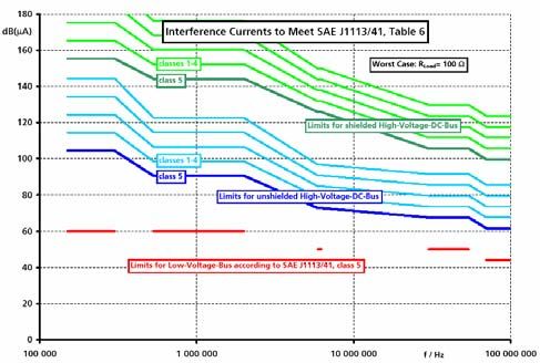
Exemplarily shown in this paper, a new approach makes it          For several years now, research has been done on the elec-
possible to specify maximum interference levels on the            tric motor and its impedance considering electromagnetic
high voltage bus. The knowledge available about modeling          noise in power electronic systems. The high-frequency
power electronic systems to be a noise source is adapted to       representation of the motor impedance depends on the elec-
answer the question how much noise is acceptable within a         tric motor principle and not on the drive application. Since
certain electrical environment [7].                               the electric motors used in electric vehicles are common ac
                                                                  machines, the high-frequency representations developed
                                                                  for other applications than electric drives can be used for
EMC BEHAVIOR OF THE ELECTRIC DRIVE
                                                                  EMI predictions in electric vehicles.
The main components of the new electric drive for automo-
tive applications are the electric motor, the power con-
verter, the power supply and the lines connecting the com-
ponents. Each of these components acts as a path for elec-
tromagnetic emissions. The power converter is known to be
the main source of EMI. So the components of the drive
system have to be analyzed being either noise source or
part of the coupling path within the car’s new electrical
system.
Power Converters                                                    Figure 3: Per-phase Representation of the AC Motor
Power electronic systems are known to be the main source          Figure 3 shows a high-frequency per-phase representation
of electromagnetic interferences within electric drive sys-       of an ac motor that has been proposed for overvoltage
tems. The high speed switching device, e.g. the insulated         analysis by Moreira [9]. The parameter Cg represents the
gate bipolar transistors (IGBT), is the noise source which        winding-to-ground capacitance. The parameter Rg is added
has to be modeled. A method to calculate the generated            in the circuit to represent the dissipative effects that exist in
EMI of power electronic devices with changing pulse pat-          the motor frame resistance. The circuit formed by the pa-
terns is introduced in [8]. Most available physics-based          rameters Rt, Lt and Ct is related to the winding turn-to-turn
models of semiconductor switches are not developed for            capacitance. The parameter Re is responsible to account for
high frequency calculations. For this reason, a simplified        the losses introduced by eddy current inside the magnetic
description of the noise source is derived.                       core. The parameter Ld represents the leakage inductance
                                                                  of the machine winding. The methodology for the parame-
                                                                  ter estimation can be found in [9].
                                                                  Traction Battery
                                                                  The battery providing power to the converter is a main part
                                                                  of the path for EMI. Therefore, the battery behavior within
                                                                  the high frequency range needs to be determined.
                                                                                            positive pole

 Figure 2: Half Bridge and its Equivalent Circuit to Pre-
                        dict EMI
Figure 2 shows the equivalent circuit to predict EMI of a
high power density inverter. The current source IS models
the current flowing into the half bridge. This current repre-
sents the source of differential mode interferences. The task                                     separator with
of the voltage source US is to model the output voltage                                           electrolyte
                                                                                                  negative electrode
which is the source of common mode interferences. Valid-
ity of these simplifications is proven in [8], thus the results                                   positive electrode

can be used for further investigations.
Electric Motor
Another crucial factor for an accurate EMI analysis is the                                        negative pole
representation of the electric motor in the EMI frequency
range. The way noise currents flow inside the machine
does not necessarily have to be determined. In fact, it is             Figure 4: Structure of Cylindrical NiMH Battery
more important to know the impedance of the electric mo-          The basic structure of a battery consists of two electrodes
tor as a part of the noise path and how this impedance var-       and an electrolyte embedded in a mechanical separator. In
ies as a function of frequency.                                   cylindrical batteries the electrodes are rolled (Figure 4),
while they are laminated in prismatic batteries. The RF- f ∗ µ 0 ∗ µ r , eff
properties result from the current path through this struc- Rint, Skin = ∗l [Ω]
4π ∗ r 2 ∗ σ eff
ture. Figure 5 demonstrates the current flow for two elec- (2)
trodes via the electrolyte. A correction factor is added for prismatic batteries to take
Hoene has presented a new approach to model the battery into account the influence of the battery’s shape. The for-
regarding its dense packaging of electrodes and the direc- mulas for low and high frequency behavior are joined by a
tion of the current flow as solid conductor [10]. formula which is not physically but empirically proven:
Rint = Rint, DC + Rint, Skin
(3)
2 2
[Ω]
I I The internal inductance for round conductors is divided
into a DC (4) and a frequency dependent part (5).
µ0 µ r , eff
Lint, DC = ∗l [H]
Figure 5: Current Path Through Battery 8 ∗π (4)
By using a homogeneous material instead of the electrode
structure, properties like the internal and the external in-
ductance or the skin effect can be predicted easily. Then µ0 ∗ µ r ,eff
Lint, HF = ∗ l [H]
the material properties of the homogeneous conductor have 16 ∗ π 3 ∗ r 2 ∗ σ eff ∗ f
(5)
to emulate the material mixture from electrodes and elec-
The total internal inductance is calculated by (6).
trolyte.
Figure 6 shows the behavior model for a single battery cell 1
in the EMC frequency range. The model is parameterized
Lint = [H]
1 1
and proved by impedance measurements on battery cells. 2
+ 2
Lint, DC Lint, Skin
The model consists of the internal inductance and resis- (6)
tance (Lint and Rint), which both depend on the frequency
due to the skin effect. Furthermore, the external inductance The external magnetic field strongly depends on the shape
is represented by Lex; the resistance of contacts by Rc. Ce and the distance of the return path of the current. In [11],
models the capacitance between the electrodes and Rch and formulas are given to calculate the inductance for standard
Vch which give a simplified description of the chemical geometries of conductors. Regarding the batteries as solid
processes. conductors, these formulas can be applied to the geometry
implemented in a specific battery. The contact resistance
RC is also parameterized according to the specific setup.
10
absolute value of impedance [Ohm]
1
0.1
measurement
simulation
0.01
0.001
Figure 6: Equivalent Circuit to Model Rf-Characteristics 0.1 1 10 100 1000 10000 100000
of Batteries in Regarded Frequency Range frequency [kHz]
Figure 7: Absolute Value of Battery Impedance
If necessary, they can be replaced by a more detailed low
90
frequency model.
The internal DC resistance is given by the cross section A
phase of impedance [°]
and the length l of the battery and the conductivity σeff of 45
the homogeneous equivalent material (all in SI units).
0
l measurement
Rint, DC = [Ω] (1) simulation
σ eff ∗ A -45
0.1 1 10 100 1000 10000 100000
To calculate the frequency dependent resistance, the skin frequency [kHz]
effect formula for round conductors is used where f is the Figure 8: Phase of Battery Impedance
frequency, µ0 the absolute permeability, µr,eff the relative
permeability of the homogenous equivalent material and r Figure 7 shows the measured and simulated absolute value
the radius of the battery. of the impedance of a cylindrical NiMH-Cell with 3.3 cm
diameter and 37 cm length, while Figure 8 shows the meas-measured and simulated phase. The simulations match the one important coupling path is crosstalk between the dif-
measured data and therefore validate the proposed ferent lines.
simplifications. So the way to describe the traction battery Besides crosstalk, the EMI radiated from the high-voltage
as a part of the noise path is appropriate for EMI prediction cables into the vehicle is an issue to be addressed. EMI
and advanced mitigation development. radiated from the high-voltage bus has to fulfill the same
standards as any other line connecting low-voltage compo-
Shielded and Unshielded Cables
nents. As the conventional procedures can be used for
The cables of the high-voltage bus connecting the power
EMC assessment of the high-voltage bus without changes,
converter with the motor and the power supply have to be
it is not further stressed in this paper.
taken into account to describe the new electric drive sys-
tem. Coupling Path Modeling
Due to the ratio between the size of the power converter For quantifying crosstalk, the underlying idea is to place
and the frequency of the EMI, power electronic applica- the cables of the high power bus close to the cables of the
tions emit the noise mainly through their lines. That’s why low power bus.
the cables for the high-voltage bus are so important during
the design process of an electrically driven vehicle.
Usually the connection between converter and motor is
kept very short to gain better results in terms of volume and
EMC. Restrictions regarding the space available within the
car demand cables for the connection to the power supply.
From the EMC point of view, there are high-voltage lines
within the system carrying the supply voltage as high as
900V.
The main question during the design process is to find out Figure 9: Layout for Inductive Coupling Modeling
if shielded cables are necessary or not. In general, shielding
can reduce the mitigations to ensure EMC within the sys- The setup is derived from the setup required for the con-
tem, but drawbacks are higher costs and reduced flexibility, ducted emission measurements according to the SAE stan-
which causes problems for the assembling. Regarding dards. The high-voltage bus cables – possibly shielded –
EMC criteria, the best solution would be a common shield- are arranged in parallel to one line representing the low-
ing of both high-voltage bus lines. Such a solution would voltage bus or any sensible signal line. The low-voltage
even aggravate the problem since the cooling conditions line is connected to a line stabilizing network (LISN) on
deteriorate, and therefore the size of the cable has to in- one side and to a component with worst-case impedance on
crease. In turn, that means higher costs and lower flexibil- the other side. Impedance of the input terminal of the
ity. component is supposed to be small for worst-case
The tradeoff between shielded cables and EMI mitigations inspection. Values for worst-case inspection are mentioned
can only be found for specific applications. Research as in [12]. In case of signal lines input terminal impedance is
presented in this paper, can provide guidelines for the deci- high ohmic, at least 100 Ω. Power input terminals are less
sions. ohmic, at least 0.1 Ω. Based on this setup the impact of an
electric drive system on the low-voltage electrical system
of a passenger car can be quantified by measurement or
COUPLING PATHS simulation with lumped parameter models.
The new electric drive system consists of several compo- As test setup two shielded cables with 70 mm2 cross sec-
nents which are connected to the new high-voltage bus tion of the inner conductor are chosen and assembled on a
only. Integrating the new electric drive system into a vehi- conducting ground plane as shown in Figure 9. In order to
cle, the noise sink to be protected against interference is the determine crosstalk, an inphase test signal is injected into
conventional electric system and its low-voltage devices both cables by a Gain-Phase Analyzer (HP4194A). The
such as the radio receiver. Existing requirements such as resulting signal is measured on a third line, representing the
those for EMC aim to the compatibility within the conven- low-voltage electric supply system or any sensitive signal
tional electrical system. In order to ensure compatibility line.
within the new system, the connections between the con- The shielded cables are modeled by the lumped parameter
ventional system and the new components have to be ana- line element model shown in Figure 10. It consists of the
lyzed. However the high-voltage system will be insulated inductance LC for the inner conductor, LS for the induc-
and does not use the car body as return conductor like the tance of the shield and the mutual inductance MCS between
low-voltage supply system does. As space for wiring har- both. They are calculated from geometrical dimensions
ness is limited in modern cars, high-voltage and low- with analytical formulas found in the literature [11, 13] as
voltage cables are arranged closely to each other. Hence well as the capacitance CS between the cable shield and the
ground plane. Resistances of the shield and the inner con-ductor RS and RC depend on the frequency due to skin ef- EMC REQUIREMENTS FOR A HIGH-VOLTAGE
fect, which influences the shielding effect and the damping BUS
at resonance frequencies. Frequency dependent effects like Based on the determined model of the coupling path, the
diffusion and dielectric losses are of outstanding impor- limits for the high-voltage bus can be derived. The underly-
tance for the correct simulation of resonances in the cou- ing idea is that the noise caused in the low-voltage system
pling paths. [14] must not exceed the limits for this system. Therefore, the
noise on the low-voltage bus can be taken directly from the
EMC requirements for automotive components.
Figure 10: One of Ten Line Elements Modeling Power
Cable
The comparison of simulation and measurement of
crosstalk from the high-power cables to a single line is
shown in Figure 11 for common mode currents on the
shielded high-voltage system.
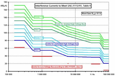
Figure 12: Limits for Interference Currents on the High-
Voltage Bus to Meet Standards for Broadband Con-
ducted Disturbances on Control/Signal Lines, Peak
Values
The low-voltage line is connected to the LISN on one side
and to a low-voltage component on the other side. Imped-
ance of the input terminal of the component is supposed to
be small for worst-case inspection. In case of signal lines,
input terminal impedance is high ohmic, at least 100 Ω.
Power input terminals are less ohmic, at least 0.1 Ω.
Figure 11: Measurement and Simulation of Crosstalk
from Shielded Power Cable
The calculations match well with the measured data and
therefore validate the model developed for the coupling
path. Coupling values below -100 dB are ignored as meas-
uring accuracy is not appropriate to resolve such high
damping values. Above 30 MHz calculated coupling is
little higher than measured levels. The coupling level at the
resonance frequency around 23 MHz is predicted exactly
with the developed frequency domain model.
Based on the results of this work, the electromagnetic noise
emitted by the electrical drive system converter can be
quantified and possible measures can be developed. Since Figure 13: Limits for Interference Currents on the High-
the two possible configurations with and without shielding Voltage Bus to Meet Standards for Broadband Con-
ducted Disturbances on Power Input Terminals, Peak
can be compared, one of the main questions can be an-
Values
swered: whether or not shielded cables between the power
converter and the power supply can replace the EMI filter. As maximum coupling occurs at resonance frequencies, the
For both configurations, the remaining effort necessary for length of the cables has to be taken into account. In order to
filtering can be determined and discussed in terms of cost, determine limits, the maximum coupling from cables of
weight and space. lengths from 0.5 m up to 2.2 m is calculated. The givenvalues for current limits on power cables can be used for (ACRDCLI) for electric vehicle (EV) traction drive
70 mm2 cables of lengths from 0.5 m up to 2.2 m. applications," presented at Thirty-Second IAS Annual
Figure 12 shows peak values of limits for interference cur- Meeting, IAS '97, 1997.
rents on the shielded and the unshielded high-voltage bus [2] L. M. Tolbert, F. Z. Peng, and T. G. Habetler, "Multi-
so, that the current limits on a closely placed signal line as level inverters for electric vehicle applications," pre-
defined in the standards [5], Table 6) are met. For compari- sented at Power Electronics in Transportation, 1998.
son the lowest limits (class 5) defined in the standards for [3] W. Dong, J.-Y. Choi, Y. Li, D. Boroyevich, F. C. Lee,
signal lines are also pictured in Figure 12. The limits on the J. Lai, and S. Hiti, "Comparative experimental evalua-
high-voltage bus are pictured for all defined classes but the tion of soft-switching inverter techniques for electric
limits fulfilling class 5 requirements are emphasized. Lim- vehicle drive applications," presented at Industry Ap-
its on the unshielded high-voltage bus are 18 dB higher plications Conference, 2001.
than standard limits. Interference currents on the shielded [4] G. Maggetto and J. Van Mierlo, "Electric and electric
high-voltage bus can be another 37 dB higher than on the hybrid vehicle technology: a survey," in Electric, Hy-
unshielded bus. brid and Fuel Cell Vehicles, IEE Seminar, 2000.
The interference current limits to fulfill the requirements [5] Society of Automotive Engineers., SAE surface vehi-
concerning interference voltage at the measurement port of cle electromagnetic compatibility (EMC) standards
the LISN [5], Table 4) are shown in Figure 13. For com- manual, 1997 ed. Warrendale, Pa.: Society of Auto-
parison, the lowest voltage limits (class 5) defined in the motive Engineers, 1997.
standards for power input terminals are also pictured con- [6] S. Guttowski, "EMV - Spezifikation als Meilenstein
verted to current limits on the low-voltage system accord- auf dem Weg zur Serienproduktion elektrisch ange-
ing to Figure 13. Again limits on the unshielded high- triebener Straßenfahrzeuge," presented at EMV 2002,
voltage bus are 18 dB higher than standard limits and limits Düsseldorf, 2002.
for the shielded high-voltage bus can be another 37 dB [7] C. Chen and X. Xu, "Modeling the conducted EMI
higher than on the unshielded bus. Limits in Figure 13 are emission of an electric vehicle (EV) traction drive,"
lower than limits in Figure 12. These limits allow the dis- presented at IEEE International Symposium on Elec-
cussion of shielding versus filtering effort in terms of costs, tromagnetic Compatibility, 1998.
weight and space. [8] E. Hoene, W. John, M. Michel, and H. Reichl,
"Evaluation and Prediction of Conducted Electro-
CONCLUSION
magnetic Interference Generated by High Power Den-
The authors of this paper have presented the EMC issues
sity Inverters," presented at European Conference on
related to the integration of an electric drive system into a
Power Electronics (EPE), 2001.
conventional passenger car. The components of the drive
[9] A. F. Moreira, T. A. Lipo, G. Venkataramanan, and S.
system have been analyzed being either noise source or
Bernet, "High-frequency modeling for cable and in-
part of the coupling path. Simulation models have been
duction motor overvoltage studies in long cable
created for EMI prediction as well as for the development
drives," IEEE Transactions on Industry Applications,
of optimized mitigations. The results of this investigation
vol. 38, pp. 1297-1306, 2002.
can be used to determine the acceptable noise levels on a
[10] E. Hoene, R. Saikly, S. Guttowski, W. John, and H.
high voltage bus of an electric drive system.
Reichl, "Rf-Properties of Automotive Traction Batter-
The simulation results have been confirmed by measure-
ies," presented at 2003 IEEE International Sympo-
ments using components of an electric drive designed for a
sium on Electromagnetic Compatibility, Istanbul,
passenger car.
Turkey, 2003.
With these results, shielding and filtering measures can be
[11] C. S. Walker, Capacitance, inductance, and crosstalk
verified and costs of the system can be optimized. Further
analysis. Boston: Artech House, 1990.
research has to be carried out to model all relevant configu-
[12] F. Broyde and E. Clavelier, "Designing Power-Line
rations.
Filter for their Worst-Case Behaviour," presented at
ACKNOWLEDGEMENT Int. Symposium on EMC, Zuerich, 1991.
The authors would like to thank Dr. W. Graupner (today [13] C. R. Paul, Introduction to electromagnetic compati-
Bombardier Transportation GmbH in Hennigsdorf, Ger- bility. New York: Wiley, 1992.
many) for initiating the idea presented in this paper and for [14] S.-P. Weber, S. Guttowski, E. Hoene, W. John, and
many helpful discussions H. Reichl, "EMI coupling from Automotive Traction
System," presented at 2003 IEEE International Sym-
REFERENCES
posium on Electromagnetic Compatibility, Istanbul,
[1] C. Chen, X. Xu, and D. M. Divan, "Conductive elec-
Turkey, 2003.
tromagnetic interference (EMI) noise evaluation for
an actively clamped resonant DC link inverterYou can also read