Outdoor Navigation System by AR - SHS Web of Conferences
←
→
Page content transcription
If your browser does not render page correctly, please read the page content below
SHS Web of Conferences 102, 04002 (2021)                                                             https://doi.org/10.1051/shsconf/202110204002
ETLTC2021

      Outdoor Navigation System by AR

      Ryohei Hashimoto1,∗ and Michael Cohen1,∗
      1
          Spatial Media Group, Computer Arts Lab; University of Aizu; Aizu-Wakamatsu, Fukushima 965-8580; Japan

                    Abstract.      Mobile map applications such as Google Maps often don’t provide detailed information about
                    facility areas such as amusement parks and university campuses. In addition, there are some people who
                    cannot reach their destination just by reading a flat map. Therefore, in this research, we have developed an AR
                    (Augmented Reality) navigation application for facilities to solve these problems. In addition, by using Kalman
                    filtering to estimate user position, we could improve the accuracy of AR objects display.

      1 Introduction
      People increasingly use smartphone navigation apps
      instead of paper maps when traveling. Many of these car-
      tographic apps not only allow users to check their current
      location using the GNSS (Global Navigation Satellite
      System, such as GPS) installed in their smartphones, but
      also have way-finding functions, guidance to selected
      destinations.

      However, navigation of outdoor sites using such map apps
      has the following problems:

            1. Detailed information needed to get to destination is
               often not included.
               In most cases, a user’s destination is not the site it-
               self but a facility located within the site. However,
               these map apps often do not provide information
               about on-site facilities. In that case, it is necessary
               to refer to a separate, detailed map dedicated to the
               site.
            2. Users should have the ability to read maps.
               These map apps still require users to be able to read
               maps. According to [1], in order to read maps, it is
               necessary to have ability to switch from subjective
               view to objective view and an ability to rotate per-
               spective mentally. There are individual differences                 Figure 1: AR navigation system for outdoor sites
               in these abilities. It is not yet clear where this differ-
               ence occurs, but this fact indicates that some people
               are not good at reading maps. For them, it can be
               difficult to reach a target facility at a site that is vis-
               ited for the first time.                                       destination by presenting information related to their
                                                                              point of view. Since AR (Augmented Reality) augments
      According to [2], the number of people who get lost
                                                                              a user’s perspective, AR can be one of the best guides for
      can decrease dramatically by preparing a guide using
                                                                              navigation. Therefore, in this paper, we propose an AR
      photographs and sentences based on visual information
                                                                              navigation system that can be used at outdoor sites. This
      from landmarks for those who cannot read maps well.
                                                                              prototype is a navigation system for outdoor sites such
      Such users are more likely to be able to reach their
                                                                              as zoos, theme parks, and university campuses, and users
           ∗ e-mail: {s1250016,mcohen}@u-aizu.ac.jp                           can smoothly go to their destinations by receiving AR

© The Authors, published by EDP Sciences. This is an open access article distributed under the terms of the Creative Commons Attribution License 4.0
(http://creativecommons.org/licenses/by/4.0/).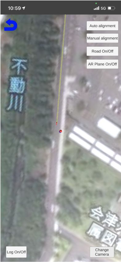
SHS Web of Conferences 102, 04002 (2021)                                                         https://doi.org/10.1051/shsconf/202110204002
ETLTC2021

      navigation suggestions.

      An outdoor site AR navigation system for smartphones
      developed to solve these two problems is reported. User
      position estimation is important to realize AR navigation.
      Therefore, this system is equipped with a Kalman filter
      that integrates data from inertial sensors in addition to the
      GNSS position sensing.

      2 Navigation apps which are published
        currently
                                                                              (a) Case when north of the   (b) Case when north of AR
      When navigating using a smartphone, it is common to
                                                                              AR space and north of the    space does not match north
      use map apps such as Google Maps [3] by Google and                      real space are aligned       of real space
      Maps [4] by Apple. However, navigation is often possible
      only along public roads with these apps. That’s because
      APIs such as the Google Maps Platform [5] don’t provide                 Figure 2: Impact of magnetometer error in AR space
      detailed information on premises such as theme parks and
      campuses.
                                                                            AR navigation that does not depend on GNSS is being
      In contrast, there exist navigation apps specialized for
                                                                            conducted. These studies explore a method of determining
      particular facilities. Examples of these include the Tokyo
                                                                            current location with markers [8] and a method of using
      Disney Resort app [6] and Tokyo Parks Navi [7]. Unlike
                                                                            landmark confirmation at intersections [9]. In addition,
      map apps such as Google Maps, these apps specialize in
                                                                            VPS (Visual Positioning Service) using imagery from
      information regarding particular premises, so it is possible
                                                                            mobile device cameras and machine learning is also being
      to navigate even in nonpublic areas where navigation is
                                                                            researched [10]. However, these methods require time
      not supported with general map apps. However, these
                                                                            and effort, such as arranging markers in various places
      apps are often published by each facility, so there is
                                                                            and recording landmark information at each intersection.
      a disadvantage that users must switch applications for
                                                                            With navigation using GNSS and a magnetometer, it
      each facility. Tokyo Parks Navi handles information for
                                                                            is possible to navigate with only the intrinsic sensors
      multiple facilities in Tokyo such as Ueno Zoo and Tokyo
                                                                            installed in a smartphone. If the environment is good, it
      Sea Life Park, but as its name indicates, the set of facilities
                                                                            is possible to obtain location accuracy within about 5 m.
      that it supports is limited to Tokyo.
                                                                            Since our system is intended for use in situations where
                                                                            the GNSS reception environment is relatively good, such
      In summary, there is the problem that there exist no
                                                                            as in amusement parks and universities, this project uses
      general-purpose navigation apps for facilities. This project
                                                                            GNSS and magnetometer for AR navigation.
      comprises research and development aimed at addressing
      this problem.
                                                                            There are several ways to configure AR navigation using
                                                                            GNSS and an magnetometer, but each method requires AR
      3 Development of in-facility AR navigation                            space to be aligned with the real space. A magnetometer
        system                                                              is used for matching azimuth, but it cannot be perfectly
                                                                            matched due to error. If the angle is off, as shown in
      3.1 Methods of Navigation                                             Fig. 2b, there is a problem that an AR object could be dis-
                                                                            played in the wrong position. In order to solve this prob-
      The usual contemporary navigation method is to draw                   lem, this project adopted a method of rendering a map in
      one’s current location obtained by GNSS and a suggested               AR space and mapping it into real space. After prelimi-
      route to the destination obtained by API access on a                  nary automatic alignment with the magnetometer, the user
      two-dimensional map displayed on a smartphone. This                   manually adjusts the azimuth. When adjusting, the over-
      is the technique used by most map and navigation apps.                lay can be calibrated by aligning a road object displayed
      However, this method requires users to be able to read                in AR with the corresponding roadway in real space.
      a map. Therefore, this method is not suitable for people
      who are not good at reading maps.
                                                                            3.2 Map services
      To solve this problem, a navigation system using AR                   There are two GIS (Geographic Information System)
      technology is proposed. The first possible method for this            services that can be readily used to display maps in AR:
      is to use GNSS and a magnetometer (electronic compass)                Google Maps and Mapbox [11]. In our proof-of-concept,
      to place navigation objects displayed in AR space.                    such service is used to draw a map and acquire a route.
      However, accuracy of GNSS varies depending upon the                   There are advantages and disadvantages regarding these
      environment in which it is used. Therefore, research on               two services, and it is not easy to choose which to use. For

                                                                        2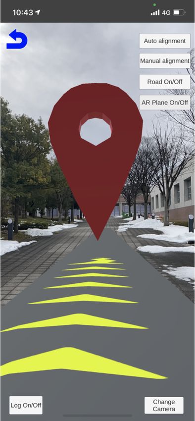
SHS Web of Conferences 102, 04002 (2021) https://doi.org/10.1051/shsconf/202110204002
ETLTC2021
example, consider how accurate the walking navigation
route in the facility is, which depends on how many
walkways in the large facilities exist in the map database.
For Tokyo Disney Resort, both Google Maps and Mapbox
have pedestrian paths, and navigation routing is accurate.
However, at Nasu Highland Park, Google Maps does
not have a walking path to some facilities, and it is
not possible to determine an optimal navigation route.
Mapbox registers a lot of walking paths in the facility,
so it is possible to determine an appropriate route. On
the other hand, at the University of Aizu, Google Maps
has some walking paths, but Mapbox may output routes
that require a round-about detour to a destination, due
to the small number of cartographic walking paths it has
registered for the premises.
(a) Facility Selection (b) Destination Selection
In this project, Unity is used for development. Mapbox
provides an SDK for Unity and has abundant examples Figure 3: Facility and Destination Selection views
for AR sample scenes, so this project uses the Mapbox
service. (Google maps also has an SDK for Unity, but its
development support doesn’t include AR sample scenes.)
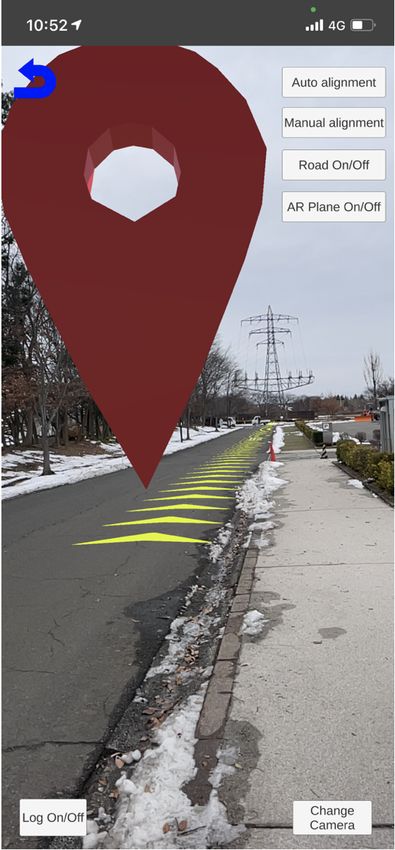
3.4.2 AR navigation to the destination
3.3 Development environment After a destination is selected by the user, the system
accesses the Mapbox API using the user’s current loca-
tion and destination coordinates as a query to calculate a
Research and development that focuses on such issues are
route. Once the route is obtained, navigation objects are
discussed in [12], which project was developed in the na-
placed along it. There are two types of navigation objects:
tive environments of both iOS and Android, and which
route objects which represent walking routes with arrows
was intended to reduce development time by matching cor-
(Fig. 4a), and waypoint objects located at each waypoint
responding program structures. In the project described in
such as intersections and T-junctions (Fig. 4b). The user
this paper, it is possible to develop a single set of source
can confirm a walking route by extended route object, and
files compatible with multiple platforms by using Unity as
can confirm each waypoint by each waypoint object. We
a cross-platform development environment. This can sig-
judged that it would be excessive to have waypoints for
nificantly reduce programming time compared to develop-
all intersections and T-junctions, so they are only located
ing platform-specifically, and it will be easier to manage
at right or left turn-points. In addition, to enable naviga-
future extensions.
tion even when the user is not looking at the smartphone, a
function that displays a recorded navigation voice guid-
ance according to the type of waypoint as the user ap-
3.4 Functions
proaches each waypoint object is implemented. The cur-
rent types of navigation voice commands are as follow.
3.4.1 Facility and destination selection
• Departure point (start)
This system expects a user to know the name of a – Walk north.
destination in advance. First, the user selects on the – Walk south.
facility selection view the facility to which the destination
belongs (Fig. 3a). When a facility is selected by the user, – Walk west.
the system displays candidate destinations belonging to – Walk east.
that facility. In this project, data about facilities has been
stored in advance for experiments, but it is preferable • Intersection (turn-point)
to implement an API that returns facility information
– Turn left.
dynamically using the facility name as a database query.
In addition, a system that allows facility managers to edit – Turn right.
facility information is also desirable.
• Destination (goal)
Next, the user selects the name of the place to go to on – You’ve arrived at destination.
the destination selection view (Fig. 3b). If the destination
is a building and has a room inside, it is also possible to For waypoint objects, start and destination markers are
indicate the room information included in the destination colored red, and intermediate markers are colored green.
by tapping the destination name.
3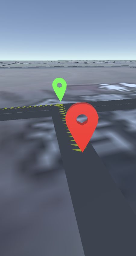
SHS Web of Conferences 102, 04002 (2021)                                                         https://doi.org/10.1051/shsconf/202110204002
ETLTC2021

      At this time, for departure point, intermediate directions
      are not supported. The navigation voice is currently ren-
      dered diotically, but it is possible to make the system so
      that the sound is heard from the direction of the next way-
      point, like Microsoft Soundscape [13].

                                                                            Figure 5: Vector diagram of xz plane view (plan perspec-
                                                                            tive) when aligning north direction, where β is y-axis ro-
        (a) Route object (series of    (b) Waypoint objects (green          tation amount, α is current smartphone azimuth, θ0 is real
        chevron arrows)                or red markers)                      space orientation of z-axis of AR space

               Figure 4: Navigation AR overlay objects
                                                                            is placed at the marker; in the latter method, walls or the
                                                                            ground are detected by image processing technology and
                                                                            AR objects are placed along their planes. Unity’s AR
      3.4.3 Matching of AR space and real space                             Foundation supports both methods, but our system uses
                                                                            markerless AR because it detects the ground (plane) and
      Before starting AR navigation, the AR space must be                   places AR objects upon it.
      aligned with the real space. The matching operation used
      by our system is to match the north of the AR space with              The AR system detects the ground when the user aims the
      the north of the real space, as described in §3.1. By us-             camera at the ground. When the system accesses Map-
      ing an magnetometer, two values representing north (mag-              box’s API to obtain a map and route data, some AR ob-
      netic north and true north) are obtained. In this project,            jects (a map around user’s current location, road objects,
      true north is used. This process can be divided into two              and navigation objects) are generated in the AR space. At
      phases: automatic adjustment that aligns a certain azimuth            this time, the user’s current location in the real space is
      with an magnetometer, and manual adjustment that brings               correctly projected into the AR space. If a plane map is
      an error closer to zero with human calibration. The auto-             drawn on a view through AR camera (device camera), it
      matic adjustment algorithm follows, where the project co-             would be difficult to see the ground in the real space. For
      ordinate system uses a left-handed arrangement in which               that reason, only road objects and navigation objects are
      the x-axis is lateral sway, the y-axis is vertical heave (grav-       drawn on the AR scene. By detecting the ground with the
      itational up), and the z-axis is longitudinal surge. Fig. 5 is        AR system, AR objects (road objects and navigation ob-
      a diagram of vectors related to this algorithm.                       jects) are aligned with the ground in real space. Since AR
                                                                            objects are placed on the plane map in the AR space, AR
      Step 1. By subtracting y-axis rotation amount β of AR                 objects won’t be displayed correctly in the real space if
      camera in AR space from current smartphone azimuth α                  the pedestrian path in the real space is a slope, as seen in
      in real space, real space orientation of z-axis of AR space           Fig. 6. To solve this problem, the heights of the AR ob-
      θ0 is obtained. That is the offset rotation amount of AR              jects are adjusted each time a new plane is detected. It is
      space.                                                                desirable to encourage users to re-detect the ground as the
                                                                            height of the ground changes, but we defer such issues for
      Step 2. Counter-rotate the map in AR space around the y-
                                                                            now.
      axis by offsetting by −θ0 .

                                                                            3.5.2 Updating coordinates of AR camera object
      3.5 Handling of AR objects
                                                                            Unity provides an API to access location information.
      3.5.1 AR system                                                       This API uses the update cycle of location information
                                                                            and the accuracy of location information as parameters.
      Currently, there are basically two types of AR: marker-               If these values are set to high level (shorter update cycle
      based AR and markerless AR. In the former method, a                   and higher accuracy), more accurate position information
      specific marker is prepared and corresponding AR object               can be obtained, but more battery energy is consumed.

                                                                        4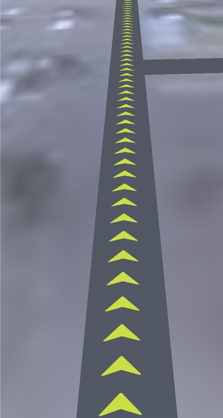
SHS Web of Conferences 102, 04002 (2021)                                                       https://doi.org/10.1051/shsconf/202110204002
ETLTC2021

      Figure 6: Misplacement of AR objects with height gradi-
      ent

      However, in this system, which needs to constantly map a
      AR space to the real space, the update cycle should be as
      short as possible, and the position accuracy should be set
      to higher accuracy. Therefore, in this system, the update
      cycle is set to 1 s and the accuracy is set to the maximum
                                                                             (a) View through device     (b) View using imagery
      (an error of about 5 m). The shortest update cycle that                camera (AR Camera)          satellite in AR space
      can be set is 0.5 s, but with that setting, the battery drains
      significantly because the AR function is overclocked.
                                                                           Figure 7: Images showing that user’s current location is
      When updating a user’s position in AR space, coordinates             plotted on a map in AR space and AR objects are displayed
      of the AR camera are changed directly. Assuming that                 correctly.
      directions of an AR space and real space are aligned, by
      mapping user’s current location (AR camera in the AR
      space) correctly on the map of the AR space, AR objects
      are displayed correctly on the "see-through" device
      (Fig. 7). However, in Unity’s AR Foundation, coordinates
      of the AR camera object are measured by dead reckoning,
      and it is impossible to change coordinates of the AR
      camera object directly. In Unity, a hierarchy of objects
      is comprised of parent-child relationship, and when a
      Transform (coordinates, orientation, scale) of a parent
      object changes, the child object inherits such relative
      parameters. Therefore, coordinates of the AR camera
      object are changed by preparing an object attached in the
      scene hierarchy as the parent of the AR camera object and
      changing coordinates of the parent object.

      Kalman filtering (described below) is processed at update
      timing of the device position information, and position of
      the AR camera at that time is synchronously calculated.
      By moving the parent object of the AR camera object so
      that the AR camera object overlays its viewport, coordi-
      nates of the AR camera in the AR space are dynamically               Figure 8: Motion of AR camera by parent object, where
      updated.                                                             A is parent of AR camera, B is parent of AR camera (af-
                                                                           ter movement), C is AR camera, D is calculated position
                                                                           (destination of AR camera)
      3.6 System configuration

      A schematic diagram of this system is shown in Fig. 9. The
      client app is composed with Maps SDK for Unity, which is             and Vector tiles API are used, which are included in maps
      an SDK for Unity of Mapbox, and AR Foundation, which                 service, and Directions API is used, which is included in
      is an AR platform of Unity. The server side is mainly com-           navigation service. Sensor data includes inertial sensors,
      posed of Mapbox services. There are two types of services            GNSS, and magnetometer. Since this app is used outdoors,
      to use: maps service, which serves map data, and nav-                a cellular network is usually used for communication with
      igation service, which serves routes. Static Images API              cloud-hosted server. A device must be online to get map

                                                                       5
SHS Web of Conferences 102, 04002 (2021) https://doi.org/10.1051/shsconf/202110204002
ETLTC2021
and route data, but since system doesn’t access the inter- First, let u(k) be true distance traveled by the AR camera
net during navigation, it can be used offline after caching from time k to time k + 1, as measured by inertial sensors
way-finding information. (accelerometer and gyro sensor) of the smartphone IMU
(Inertial Measurement Unit). Then, subsequent noiseless
position can be expressed as
x(k + 1) = x(k) + u(k). (2)
The following equation of perturbed state is obtained from
extension of Equation (2):
x(k + 1) = x(k) + u(k) + u(k), (3)
where u(k) is the system noise, including centered noise
of the inertial sensor having mean value vector 0 (zero
vector) and covariance matrix Q.
Next, since the value output by GNSS is the absolute lo-
cation of the smartphone on the earth, it can be associ-
ated with coordinates in Unity space and designated y(k).
Then, the following observation equation is obtained:
y(k) = x(k) + w(k), (4)
where w(k) is the observation noise of GNSS, having
mean value vector 0 and covariance matrix R.
When the Kalman filter is programmed using equations (3)
Figure 9: System overview and (4) as the state space model of the system, the follow-
ing time-updated compound equation of the Kalman filter
is obtained:
4 User position estimation using Kalman x̂(k|k − 1) = x̂(k − 1|k − 1) + u(k − 1),
filtering P(k|k − 1) = P(k − 1|k − 1) + Q,
G(k) = P(k|k − 1)(P(k|k − 1) + R)−1 , (5)
If the location estimation is too far from the true value, an
AR object cannot be placed in its proper position, and nav- x̂(k|k) = x̂(k|k − 1) + G(k)(y(k) − x̂(k|k − 1)),
igation becomes impossible. Therefore, this system aims P(k|k) = (I − G(k))P(k|k − 1),
to improve estimation accuracy of user position by imple-
menting a Kalman filter. A Kalman filter is a filter for where x̂(k|k − 1) is a priori state estimate value, P(k|k − 1)
estimating system status using noisy (inaccurate) obser- is a priori estimate covariance matrix, 0 ≤ G(k) ≤ 1 is the
vations by minimizing statistically estimated error (mean Kalman gain, x̂(k|k) is a posteriori state estimate value,
square deviation). Several studies have been conducted on P(k|k) is a posteriori estimate covariance matrix, and I is
the improvement of GNSS accuracy by Kalman filter [14] the identity matrix.
[15]. In this project, since movement information of the
AR camera measured by inertial sensor of the smartphone Initial values of state estimate value and the estimate co-
can be used, a Kalman filter that integrates this data and variance matrix are expressed as
GNSS data was implemented.
x̂(0|0) = x0 ,
(6)
P(0|0) = γI,
4.1 Time update formula
where x(0|0) is the initial coordinates of the AR camera,
Estimated state x(k) is defined as to be determined by the user before starting of AR navi-
! gation, and γ is one of the calibration parameters, within
x(k)
x(k) = , (1) range 0–1000.
z(k)
where x(k) is the true state at time k and x(k), z(k) are the 4.2 Experiment and result
true x and z coordinates of a user in Unity space at time
k. In the following, the relationship between the output of Adjustment parameter values of this Kalman filter were
each sensor and the state x is derived. determined heuristically by walking experiments as fol-
lows.
6SHS Web of Conferences 102, 04002 (2021) https://doi.org/10.1051/shsconf/202110204002
ETLTC2021
Figure 11: Verification experiment results
Figure 10: Walking route in verification experiment
location information was used to determine if the device
has entered tunnels.
The result of the verification experiment is shown in
Q = σ2v δi j Fig. 11. As soon as the device enters T1 or T2, the GNSS
R = σ2w δi j (7) data starts to include a lot of noise, but the filtered data
contains negligible noise.
γ = 1.0
Here, σv = 0.2, σw = Aη, A is the horizontal accuracy of
GNSS (unit is meter), and η is the adjustment magnifica- 5 Conclusion
tion of σw , calculated as We configured a navigation app for location-based facili-
ties and developed an AR navigation function. In addition,
0.3 (accuracy < 10) a Kalman filter was implemented to enable navigation that
η= 0.5 (10 ≤ accuracy < 30)
(8)
is not easily degradable by inaccuracy of GNSS.
3
(30 ≤ accuracy),
For this project, Mapbox’s API was used for route acqui-
and δi j is the Kronecker delta. The adjustment magni-
sition, but depending on the facility, sufficient navigation
fication is changed according to the accuracy of GNSS
may not be possible, so in such cases it would be nec-
to improve filtering performance. For example, when
essary to build a route acquisition and registration system.
the accuracy is 5 m, we want the system to strongly trust
In addition, a cartographic management system for facility
observed values, but at 10 m, we want the system to
managers would also be required. In the future, we would
trust estimated values somewhat more. However, if the
like to develop a system that includes these functions and
accuracy of GNSS is used as observation noise as it is, the
have facility users try it to conform usability. It is also con-
observed values will be strongly trusted even at 10 m.
ceivable to build a VPS specialized for a facility. Further-
more, we would like to consider an AR eyewear version of
No method has been discovered to automatically de-
this system.
termine these parameters. This time, the approximate
optimum value was derived by repeating walking experi-
ments. Although these are defined as above in this system, References
it is acknowledged that there is an error from the optimum
value in reality. [1] Bad at Reading Maps? Maybe Your Brain Just
Needs Better Maps | WIRED, https://www.wired.
A verification experiment was conducted to confirm the com/2013/11/map-sense/, (Accessed on 01/08/2021)
effectiveness of the above settings. The walking route [2] "I can’t read the map!" Lamentation of those who get
is shown in Fig. 10. Since the walking route used in the lost | AERA dot. | Toyo Keizai Online | New standard
experiment had relatively good environment for GNSS for economic news, https://toyokeizai.net/articles/-/
reception, objects imitating tunnels were placed in the AR 158329, (Accessed on 01/08/2021)
space to intentionally reduce GNSS reception intensity. [3] Google Maps, https://www.google.com/maps/, (Ac-
T1 and T2 in Fig. 10 are simulated tunnel objects. When cessed on 10/31/2020)
the tracking device enters T1 and T2, the accuracy [4] Maps — Apple, https://www.apple.com/maps/, (Ac-
becomes 10 m and 30 m, respectively. The original GNSS cessed on 10/31/2020)
7SHS Web of Conferences 102, 04002 (2021) https://doi.org/10.1051/shsconf/202110204002
ETLTC2021
[5] Geo-location APIs | Google Maps Platform | Google [11] Mapbox, https://www.mapbox.com, (Accessed on
Cloud, https://cloud.google.com/maps-platform, 12/03/2020)
(Accessed on 10/31/2020) [12] R. Mannari, Development of a navigation sys-
[6] Tokyo Disney Resort App, https://www. tem that enables route guidance within the facil-
tokyodisneyresort.jp/topics/tdrapp.html, (Accessed ity: Development of implementation method that
on 10/31/2020) realizes common operation on multiple mobile
[7] Tokyo Parks Navi, https://www.tokyo-park.or.jp/ platforms, https://www.iplab.cs.tsukuba.ac.jp/paper/
special/tokyoparksnavi/index.html, (Accessed on reports/2014/mannari_report.pdf (2015), (Accessed
10/31/2020) on 11/03/2020)
[8] H. Okada, T. Yoshimi, M. Motokurumada, M. Ohta, [13] Microsoft Soundscape — Microsoft Research,
K. Yamashita, AR Navigation System Using Markers https://www.microsoft.com/en-us/research/product/
for Positioning, in Information Processing Society of soundscape/, (Accessed on 12/10/2020)
Japan Kansai Branch Conf. Proc. (2011) [14] S. Son, Research on improving GPS indepen-
[9] R. Yano, T. Nitta, K. Ishikawa, M. Yanagisawa, dent positioning accuracy using Kalman filter,
N. Togawa, A Navigation System based on Land- http://www.denshi.e.kaiyodai.ac.jp/jp/assets/files/
mark Recognition by Glass-type Wearable Devices, pdf/investigation/20070823.pdf (2007), (Accessed
in Multimedia, Distributed, Cooperative, and Mobile on 11/05/2020)
Symp. (2016), pp. 419–427 [15] R. Ogawara, H. Hatano, M. Fujii, A. Itoh, Y. Watan-
[10] Google AI Blog: Using Global Localization to Im- abe, Location Estimation System Based on GPS Po-
prove Navigation, https://ai.googleblog.com/2019/ sitioning and Sensor Information, Information Pro-
02/using-global-localization-to-improve.html, (Ac- cessing Society of Japan Conf. Proc. 56, 2 (2015)
cessed on 12/10/2020)
8You can also read