INSTRUCTION MANUAL AQ S391 - Bay control IED - Arcteq
←
→
Page content transcription
If your browser does not render page correctly, please read the page content below
INSTRUCTION MANUAL

AQ S391 – Bay control IED
Instruction manual –AQ S391 bay control IED                                      2 (63)

 Revision         1.01
 Date             January 2012
 Changes                 -   HW construction and application drawings revised

 Revision         1.02
 Date             May 2012
 Changes                 -   Synchrocheck chapter revised
                         -   Voltage measurement module revised
                         -   CPU module description added
                         -   Binary input module description revised
                         -   IRIG-B information added
                         -   Updated ordering information and type designation
                         -   Technical data revised

 Revision         1.03
 Date             July 2012
 Changes                 -   Synch check parameter updates

 Revision         1.04
 Date             6.10.2015
 Changes                 -   Updated parameters

 Revision         1.05
 Date             18.10.2019
 Changes                 -   Updated construction and installation chapter

 Revision         1.06
 Date             23.6.2020
 Changes                 -   Added redundant power supply, possibility to remove
                             display.

 Revision         1.07
 Date                    22.01.2021
 Changes                 -   Removed statement that binary input modules are
                             capable of IRIG-B.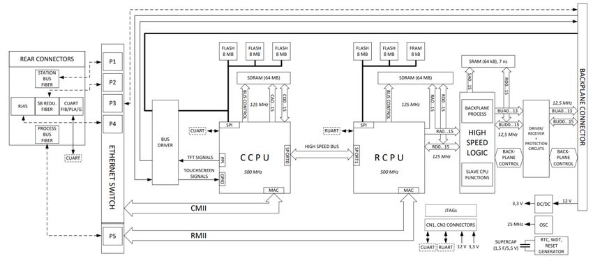
Instruction manual –AQ S391 bay control IED                                                                                           3 (63)

TABLE OF CONTENTS

1      GENERAL ............................................................................................................................... 5
2      APPLICATION........................................................................................................................ 6
3      MAIN CHARACTERISTICS OF THE AQ S391 BAY CONTROL IED ................................ 7
3.1    System design ....................................................................................................................... 7
4      SOFTWARE SETUP OF THE IED ........................................................................................ 9
4.1    Circuit breaker control block ............................................................................................... 9
    4.1.1        Application.................................................................................................................. 9
    4.1.2        Mode of operation ..................................................................................................... 9
    4.1.3        Available internal status variable and command channel ................................. 10
    4.1.4        Configuration examples .......................................................................................... 13
4.2    Disconnector control function ........................................................................................... 14
    4.2.1        Application................................................................................................................ 14
    4.2.2        Mode of operation ................................................................................................... 14
    4.2.3        Available internal status variable and command channel ................................. 15
    4.2.4        Configuration example............................................................................................ 18
4.3    Dead line detection function ............................................................................................. 18
4.4    Voltage transformer supervision function (VTS) ............................................................ 20
4.5    Synchrocheck function du/df (25).................................................................................... 24
5      APPLICATION EXAMPLES ................................................................................................ 34
5.1    One and half circuit breaker configuration ..................................................................... 34
5.2    IED IO Positions in one and half circuit breaker configuration .................................... 35
6      CONSTRUCTIONS AND INSTALLATION ........................................................................ 36
6.1    CPU Module......................................................................................................................... 38
6.2    Power supply module ......................................................................................................... 40
6.3    Binary input modules ......................................................................................................... 42
6.4    Singaling binary output modules ...................................................................................... 45
6.5    9DI + BNC IRIG-B ............................................................................................................... 48
6.6    mA input module ................................................................................................................. 49
6.7    Tripping module .................................................................................................................. 50
6.8    RTD module ......................................................................................................................... 50
6.9    Voltage measurement module .......................................................................................... 53
6.10 Current measurement module .......................................................................................... 54
6.11 Installation and dimensions .............................................................................................. 55
7      TECHNICAL DATA .............................................................................................................. 57
7.1    Monitoring functions .......................................................................................................... 57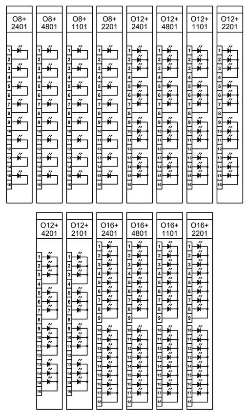
Instruction manual –AQ S391 bay control IED                                                                                            4 (63)

7.2    Control functions ................................................................................................................ 57
7.3    Hardware.............................................................................................................................. 58
    Power supply module ............................................................................................................. 58
    Current measurement module .............................................................................................. 58
    Voltage measurement module .............................................................................................. 59
    High speed trip module .......................................................................................................... 59
    Binary output module ............................................................................................................. 59
    Binary input module ................................................................................................................ 59
    mA input module ..................................................................................................................... 60
7.4    Tests and environmental conditions ................................................................................ 60
    Disturbance tests .................................................................................................................... 60
    Voltage tests ............................................................................................................................ 60
    Mechanical tests ..................................................................................................................... 61
    Casing and package ................................................................................................................ 61
    Environmental conditions and Lifetime ............................................................................... 61
8      ORDERING INFORMATION ............................................................................................... 62
9      REFERENCE INFORMATION............................................................................................. 63
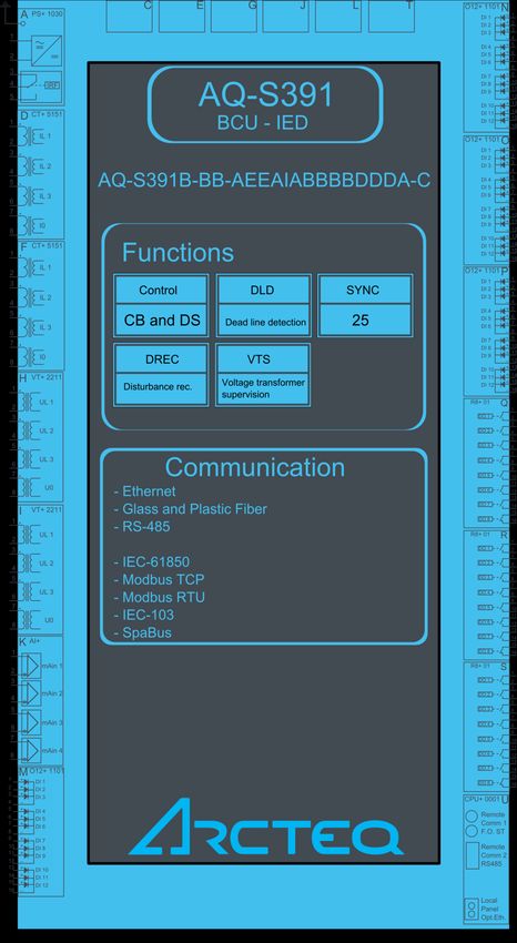
Instruction manual –AQ S391 bay control IED                                      5 (63)

1 GENERAL
  The AQ S391 bay control IED is a member of the AQ-300 product line. The AQ-300
  protection product line in respect of hardware and software is a modular device. The
  hardware modules are assembled and configured according to the application IO
  requirements and the software determines the available functions. This manual
  describes the specific application of the AQ S391 bay control IED. All generic AQ 300
  series features such as color touch screen HMI but can be manufactured also without
  any displays. Wide range of communication protocols including IEC 61850, DNP3,
  IEC101, IEC103 and IEC104 are available in this device as well.
Instruction manual –AQ S391 bay control IED                                      6 (63)

2 APPLICATION
   The AQ S391 bay control IED is suitable to various types of control and monitoring
   applications in extra-high voltage, high voltage and medium voltage applications. The
   modular hardware construction offers required options for different kind of bay
   configurations in terms of type and quantity of analogue and digital signals. The
   versatile programmable software logic allows for extensive customization of provided
   standard configurations.

   The IED may be applied to single or double breaker arrangements both in single or
   double busbar configurations. Control and monitoring of full diameter of one and half
   circuit breaker arrangement can be realized with a single IED as well.

   Motorized switching devices can be controlled from remote control system through
   communication or locally using the HMI. Synchrocheck function is provided for safe
   closing of circuit breakers.
Instruction manual –AQ S391 bay control IED                                           7 (63)

3 MAIN CHARACTERISTICS OF THE AQ S391 BAY CONTROL
  IED
   -   Flexible and modular hardware construction allowing for multiple sets of current and
       voltage measurement modules, digital input and output modules and mA input
       modules
   -   Flexible software adaptation to different busbar and interlocking schemes using
       programmable logic functions
   -   Configurable MIMIC display
   -   Touch screen (TFT) colour display
   -   Local and remote control and/or status indication of up to 12 controllable objects
   -   Direct control mode or select before execute control mode
   -   CT supervision (CTS)
   -   Dead line detection features (DLD)
   -   Voltage transformer supervision (VTS)
   -   Synchrocheck and synchroswitch function over multiple circuit breakers
   -   Optional redundant power supply (80-300Vac/dc or 48Vdc)
   -   Programmable disturbance recorder for up to 100 records stored in non-volatile
       memory
   -   Event recorder for up to 10000 latest events stored in non-volatile memory
   -   IED time synchronization (e.g. SNTP or IRIG-B)
   -   Wide range of communication protocols, including IEC 61850
   -   IED self supervision functionality

3.1 SYSTEM DESIGN

   The AQ-300 protection device family is a scalable hardware platform to adapt to
   different applications. Data exchange is performed via a 32-bit high-speed digital non-
   multiplexed parallel bus with the help of a backplane module. Each module is
   identified by its location and there is no difference between module slots in terms of
   functionality. The only restriction is the position of the CPU module because it is
   limited to the “CPU” position. The built-in self-supervisory function minimizes the risk
   of device malfunctions.
Instruction manual –AQ S391 bay control IED   8 (63)

Figure 1 CPU block diagram
Instruction manual –AQ S391 bay control IED                                          9 (63)

4 SOFTWARE SETUP OF THE IED
      In this chapter are presented the protection and control functions as well as the
      monitoring functions.

        Name           IEC       ANSI   Description
        CB Control      -          -    Circuit breaker control
        DS Control      -          -    Disconnector control
        DLD             -          -    Dead line detection
        VTS             -         60    Voltage transformer supervision
        CTS             -               Current transformer supervision
        SYN25         SYNC        25    Synchro-check function Δf, ΔU, Δφ
        DREC            -          -    Disturbance recorder
      Table 4-1 Available control and monitoring functions

 4.1 CIRCUIT BREAKER CONTROL BLOCK

4.1.1           APPLICATION

      The circuit breaker control block can be used to integrate the circuit breaker control of
      the AQ 300 device into the station control system and to apply active scheme screens
      of the local LCD of the device.

4.1.2           MODE OF OPERATION

      The circuit breaker control block receives remote commands from the SCADA system
      and local commands from the local LCD of the device, performs the prescribed
      checking and transmits the commands to the circuit breaker. It processes the status
      signals received from the circuit breaker and offers them to the status display of the
      local LCD and to the SCADA system.

      Main features:

  •     Local (LCD of the device) and Remote (SCADA) operation modes can be enabled or
        disabled individually.
  •     The signals and commands of the synchro check / synchro switch function block can be
        integrated into the operation of the function block.
  •     Interlocking functions can be programmed by the user applying the inputs “EnaOff” and
        “EnaOn”, using the graphic equation editor.
Instruction manual –AQ S391 bay control IED 10 (63)
• Programmed conditions can be used to temporarily disable the operation of the
function block using the graphic equation editor.
• The function block supports the control models prescribed by the IEC 61850 standard.
• All necessary timing tasks are performed within the function block:
o Time limitation to execute a command
o Command pulse duration
o Filtering the intermediate state of the circuit breaker
o Checking the synchro check and synchro switch times
o Controlling the individual steps of the manual commands
• Sending trip and close commands to the circuit breaker (to becombined with the trip
commands of the protection functions and with the close command of the automatic
reclosing function; the protection functions and the automatic reclosing function
directly gives commands to the CB). The combination is made graphically using the
graphic equation editor
• Operation counter
• Event reporting
4.1.3 AVAILABLE INTERNAL STATUS VARIABLE AND COMMAND CHANNEL
To generate an active scheme on the local LCD, there is an internal status variable
indicating the state of the circuit breaker. Different graphic symbols can be assigned
to the values. (See AQtivate 300 software instructions for more details).
Status variable Title Explanation
CB1Pol_stVal_Ist_ Status Can be:
0: Intermediate
1: Off
2: On
3:Bad
Table 4-2: Status variable of the circuit breaker control
The available control channel to be selected is:
Command channel Title Explanation
CB1Pol_Oper_Con_ Operation Can be:
On
Off
Table 4-3: Command channel of the circuit breaker control
Using this channel, the pushbuttons on the front panel of the device can be assigned
to close or open the circuit breaker. These are the “Local commands”.Instruction manual –AQ S391 bay control IED 11 (63)
Figure 4-1: Function block symbol of circuit breaker control
The binary input and output status signals of the circuit breaker control are listed in
tables below.Instruction manual –AQ S391 bay control IED 12 (63)
Binary status signal Title Explanation
CB1Pol_Local_GrO_ Local If this input is active, the circuit breaker can be
controlled using the local LCD of the device.
CB1Pol_Remote_GrO_ Remote If this input is active, the circuit breaker can be
controlled via remote communication channels of
the SCADA system.
CB1Pol_SynOK_GrO_ SynOK This input indicates if the synchron state of the
voltage vectors at both sides of the circuit breaker
enables the closing command. This signal is usually
generated by the synchro check/ synchro switch
function. If this function is not available, set the
input to logic true.
CB1Pol_EnaOff_GrO_ EnaOff The active state of this input enables the opening of
the circuit breaker. The state is usually generated
by the interlocking conditions defined by the user.
CB1Pol_EnaOn_GrO_ EnaOn The active state of this input enables the closing of
the circuit breaker. The state is usually generated
by the interlocking conditions defined by the user.
CB1Pol_BlkProc_GrO_ BlkProc The active state of this input blocks the operation of
the circuit breaker. The conditions are defined by
the user.
CB1Pol_stValOff_GrO_ stValOff Off state of the circuit breaker.
CB1Pol_stValOn_GrO_ stValOn On state of the circuit breaker.
CB1Pol_ExtTrip_GrO_ ExtTrip External trip command for the circuit breaker (e.g.
from protection). This signal is considered when
evaluating unintended operation.
Table 4-4: The binary input status signals of the circuit breaker control
Binary status signal Title Explanation
CB1Pol_CmdOff_GrI_ Off Command Off command impulse, the duration of
which is defined by the parameter “Pulse
length”
CB1Pol_CmdOn_GrI_ On Command On command impulse, the duration of
which is defined by the parameter “Pulse
length”
CB1Pol_StartSW_GrI_ Start Synchro-switch If the synchro check/synchro switch
function is applied and the synchron state
conditions are not valid for the time
defined by the parameter “Max.SynChk
time”, then this output triggers the synchro
switch function (see synchro check/
synchro switch function block description).
CB1Pol_Oper_GrI_ CB Operated An impulse with a duration of 150 ms at
any operation of the circuit breaker
CB1Pol_SelfOper_GrI_ Unintended Oper This output is logic true if the status of the
circuit breaker has changed without
detected command from the SCADA
system or on the input “Ext trip”
CB1Pol_Opened_GrI_ Opened The filtered status signal for opened state
of the circuit breaker
CB1Pol_Closed_GrI_ Closed The filtered status signal for closed state of
the circuit breaker
Table 4-5: The binary output status signals of the decision logicInstruction manual –AQ S391 bay control IED 13 (63)
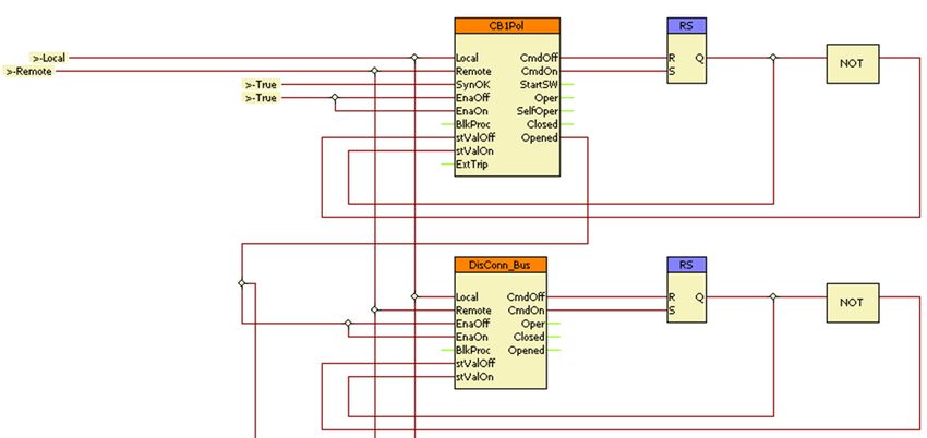
4.1.4 CONFIGURATION EXAMPLES
Example 1
Figure 4-2: Simulation of the circuit breaker (and disconnectors; detail)
In the Figure above the local/remote selection is made by another function block
(Common).
In VB1Pol, synchro check is not applied, the input “SynOK” is programmed for
constant “True”.
The circuit breaker can be switched any time, no interlocking is needed, the “EnaOff”
and “EnaOn” are programmed for constant “True”. (However, note the similar
DisConn_Bus function block in the Figure above.)
The function block does not need to be blocked; the “BlkProc” input is not connected.
The CB is simulated by an RS flip-flop, the status inputs are connected to the
simulated signals.Instruction manual –AQ S391 bay control IED 14 (63)
4.1.4.1 Example 2
Figure 4-3: A simple application
In Figure 4-3 above the local/remote selection is made by another function block
(Common).
In VB1Pol, synchro check is not applied, the input “SynOK” is programmed for
constant “True”.
Interlocking is applied; the “EnaOff” and “EnaOn” are programmed with external
binary input signals.
The function block does not need to be blocked; the “BlkProc” input is not connected.
The CB status inputs are connected to the binary input signals.
The commands are directed to another graphic page (to be “OR”-ed with the signals
of the protection and automatic reclosing functions).
4.2 DISCONNECTOR CONTROL FUNCTION
4.2.1 APPLICATION
The disconnector control block can be used to integrate the disconnector control of
the AQ 300 device into the station control system and to apply active scheme screens
of the local LCD of the device.
4.2.2 MODE OF OPERATION
The disconnector control block receives remote commands from the SCADA system
and local commands from the local LCD of the device, performs the prescribed
checking and transmits the commands to the disconnector. It processes the statusInstruction manual –AQ S391 bay control IED 15 (63)
signals received from the disconnector and offers them to the status display of the
local LCD and to the SCADA system.
Main features:
• Local (LCD of the device) and Remote (SCADA) operation modes can be enabled or
disabled individually.
• Interlocking functions can be programmed by the user applying the inputs “EnaOff” and
“EnaOn”, using the graphic equation editor.
• Programmed conditions can be used to temporarily disable the operation of the
function block using the graphic equation editor.
• The function block supports the control models prescribed by the IEC 61850 standard.
• All necessary timing tasks are performed within the function block:
o Time limitation to execute a command
o Command pulse duration
o Filtering the intermediate state of the disconnector
o Controlling the individual steps of the manual commands
• Trip and close commands to the disconnector
• Operation counter
• Event reporting
4.2.3 AVAILABLE INTERNAL STATUS VARIABLE AND COMMAND CHANNEL
To generate an active scheme on the local LCD, there is an internal status variable
indicating the state of the circuit breaker. Different graphic symbols can be assigned
to the values. (See AQtivate 300 software instructions for more details).
Status variable Title Explanation
DisConn l_stVal_Ist_ Status Can be:
0: Intermediate
1: Off
2: On
3:Bad
Table 4-6: Status variable of the disconnector control
The available control channel to be selected is:Instruction manual –AQ S391 bay control IED 16 (63)
Command channel Title Explanation
DisConn _Oper_Con_ Operation Can be:
On
Off
Table 4-7: Command channel of the disconnector control
Using this channel, the pushbuttons on the front panel of the device can be assigned
to close or open the disconnector. These are the “Local commands”.
Figure 4-4: The symbol of the function block
The binary input and output status signals of the disconnector control are listed in
tables below.Instruction manual –AQ S391 bay control IED 17 (63)
Binary status signal Title Explanation
DisConn_Local_GrO_ Local If this input is active, the disconnector can be
controlled using the local LCD of the device.
DisConn_Remote_GrO_ Remote If this input is active, the disconnector can be
controlled via remote communication channels of
the SCADA system.
DisConn_EnaOff_GrO_ EnaOff The active state of this input enables the opening of
the disconnector. The state is usually generated by
the interlocking conditions defined graphically by
the user.
DisConn_EnaOn_GrO_ EnaOn The active state of this input enables the closing of
the disconnector. The state is usually generated by
the interlocking conditions defined graphically by
the user.
DisConn_BlkProc_GrO_ BlkProc The active state of this input blocks the operation of
the disconnector. The conditions are defined
graphically by the user.
DisConn_stValOff_GrO_ stValOff Off state of the disconnector.
DisConn_stValOn_GrO_ stValOn On state of the disconnector.
Table 4-8: The binary input status signals of the disconnector control
Binary status signal Title Explanation
DisConn_CmdOff_GrI_ Off Command Off command impulse, the duration of
which is defined by the parameter “Pulse
length”
DisConn_CmdOn_GrI_ On Command On command impulse, the duration of
which is defined by the parameter “Pulse
length”
DisConn_Oper_GrI_ CB Operated An impulse with a duration of 150 ms at
any operation of the disconnector
DisConn_SelfOper_GrI Unintended Oper This output is logic true if the status of the
_ disconnector has changed without
detected command from the SCADA
system or on the input “Ext trip”
DisConn_Opened_GrI_ Opened The filtered status signal for opened state
of the disconnector
DisConn_Closed_GrI_ Closed The filtered status signal for closed state of
the disconnector
Table 4-9: The binary output status signals of the disconnector controlInstruction manual –AQ S391 bay control IED 18 (63)
4.2.4 CONFIGURATION EXAMPLE
Figure 4-5: Simulation of the disconnector (and circuit breaker; detail)
In the Figure above the local/remote selection is made by another function block
(Common).
The disconnector cannot be switched any time: interlocking is needed; the “EnaOff”
and “EnaOn” are programmed for the “Opened” state of the circuit breaker.
The function block does not need to be blocked; the “BlkProc” input is not connected.
The disconnector is simulated by an RS flip-flop, the status inputs are connected to
the simulated signals.
4.3 DEAD LINE DETECTION FUNCTION
The “Dead Line Detection” (DLD) function generates a signal indicating the dead or
live state of the line. Additional signals are generated to indicate if the phase voltages
and phase currents are above the pre-defined limits.
The task of the “Dead Line Detection” (DLD) function is to decide the Dead line/Live
line state.
Criteria of “Dead line” state: all three phase voltages are below the voltage setting
value AND all three currents are below the current setting value.Instruction manual –AQ S391 bay control IED 19 (63) Criteria of “Live line” state: all three phase voltages are above the voltage setting value. Dead line detection function is used in the voltage transformer supervision function also as an additional condition. In the figure below is presented the operating logic of the dead line detection function. Figure 4-6: Principal scheme of the dead line detection function The function block of the dead line detection function is shown in figure bellow. This block shows all binary input and output status signals that are applicable in the AQtivate 300 software. Figure 4-7: The function of the dead line detection function The binary input and output status signals of the dead line detection function are listed in tables below.
Instruction manual –AQ S391 bay control IED                                                          20 (63)

   Table 4-10: The binary input signal of the dead line detection function

   Table 4-11: The binary output status signals of the dead line detection function

   Table 4-12Setting parameters of the dead line detection function

    Parameter       Setting value, range   Description
                    and step
    Operation       On                     Operating mode selection for the function. Operation can
                    Off                    be either disabled “Off” or enabled “On”. Default setting is
                                           enabled.
    Min. operate    10…100 % by step of    Minimum voltage threshold for detecting the live line
    voltage         1%                     status. All measured phase to ground voltages have to be
                                           under this setting level. Default setting is 60 %.
    Min. operate    8…100 % by step of     Minimum current threshold for detecting the dead line
    current         1%                     status. If all the phase to ground voltages are under the
                                           setting “Min. operate voltage” and also all the phase
                                           currents are under the “Min. operate current” setting the
                                           line status is considered “Dead”. Default setting is 10 %.

4.4 VOLTAGE TRANSFORMER SUPERVISION FUNCTION (VTS)

   The voltage transformer supervision function generates a signal to indicate an error in
   the voltage transformer secondary circuit. This signal can serve, for example, a
   warning, indicating disturbances in the measurement, or it can disable the operation
Instruction manual –AQ S391 bay control IED 21 (63)
of the distance protection function if appropriate measured voltage signals are not
available for a distance decision.
The voltage transformer supervision function is designed to detect faulty asymmetrical
states of the voltage transformer circuit caused, for example, by a broken conductor in
the secondary circuit. The voltage transformer supervision function can be used for
either tripping or alarming purposes.
The voltage transformer supervision function can be used in three different modes of
application:
Zero sequence detection (for typical applications in systems with grounded neutral):
“VT failure” signal is generated if the residual voltage (3Uo) is above the preset
voltage value AND the residual current (3Io) is below the preset current value
Negative sequence detection (for typical applications in systems with isolated or
resonant grounded (Petersen) neutral): “VT failure” signal is generated if the negative
sequence voltage component (U2) is above the preset voltage value AND the negative
sequence current component (I2) is below the preset current value.
Special application: “VT failure” signal is generated if the residual voltage (3Uo) is
above the preset voltage value AND the residual current (3Io) AND the negative
sequence current component (I2) are below the preset current values.
The voltage transformer supervision function can be triggered if “Live line” status is
detected for at least 200 ms. The purpose of this delay is to avoid mal-operation at
line energizing if the poles of the circuit breaker make contact with a time delay. The
function is set to be inactive if “Dead line” status is detected. If the conditions
specified by the selected mode of operation are fulfilled then the voltage transformer
supervision function is triggered and the operation signal is generated. When the
conditions for operation are no longer fulfilled, the resetting of the function depends
on the mode of operation of the primary circuit:
• If the “Live line” state is valid, then the function resets after approx. 200 ms of
time delay.
• If the “Dead line” state is started and the “VTS Failure” signal has been
continuous for at least 100 ms, then the “VTS failure” signal does not reset; it is
generated continuously even when the line is in a disconnected state. Thus, the
“VTS Failure” signal remains active at reclosing.Instruction manual –AQ S391 bay control IED 22 (63)
• If the “Dead line” state is started and the “VTS Failure” signal has not been
continuous for at least 100 ms, then the “VTS failure” signal resets.
Preparation
VTS
UL1 Negative
Sequence
UL2
Fourier
UL3 Zero
Sequence
Parameters
VTS
Status signals
Algorithm Decision
Dead Line
Detection Logic
DLD
IL1 Negative
Sequence
IL2
Fourier
IL3 Zero
Sequence
Status
signals
Figure 4-8: Operation logic of the voltage transformer supervision and dead line detection.
The voltage transformer supervision logic operates through decision logic presented in
the following figure.Instruction manual –AQ S391 bay control IED 23 (63)
DLD_StIL1_GrI
_ DLD_
DLD_StIL2_GrI DeadLine_
_ GrI_
DLD_StIL3_GrI
_ OR NOT
DLD_StUL1_GrI
_
DLD_StUL2_GrI
_
DLD_StUL3_GrI
_ DLD_
LineOK_GrI_
AND
t S
200
R AND
VTS_Fail_int_
t S VTS_
NOT 100 OR t Fail_GrI_
VTS_Blk_GrO_ OR 100 AND
NOT R
Figure 4-9: Decision logic of the voltage transformer supervision function.
NOTE: For the operation of the voltage transformer supervision function the “ Dead
line detection function” must be operable as well: it must be enabled by binary
parameter
The symbol of the function block in the AQtivate 300 software
The function block of voltage transformer supervision function is shown in figure
below. This block shows all binary input and output status signals that are applicable
in the graphic equation editor.
Figure 4-10: The function block of the voltage transformer supervision function
The binary input and output status signals of voltage transformer supervision function
are listed in tables below.Instruction manual –AQ S391 bay control IED 24 (63)
Binary status signal Explanation
VTS_Blk_GrO_ Output status defined by the user to disable the voltage
transformer supervision function.
Table 4-13: The binary input signal of the voltage transformer supervision function
Binary output signals Signal title Explanation
VTS_Fail_GrI VT Failure Failure status signal of the VTS function
Table 4-14: The binary output signal of the voltage transformer supervision function
4.5 SYNCHROCHECK FUNCTION DU/DF (25)
Several problems can occur in the power system if the circuit breaker closes and
connects two systems operating asynchronously. The high current surge can cause
damage in the interconnecting elements, the accelerating forces can overstress the
shafts of rotating machines or the actions taken by the protective system can result in
the eventual isolation of parts of the power system.
To prevent such problems, this function checks if the systems to be interconnected
are operating synchronously. If yes, then the close command is transmitted to the
circuit breaker. In case of asynchronous operation, the close command is delayed to
wait for the appropriate vector position of the voltage vectors on both sides of the
circuit breaker. If the conditions for safe closing cannot be fulfilled within an expected
time, then closing is declined.
NOTE: For capacitive reference voltage measurement, the voltage measurement
card can be ordered withInstruction manual –AQ S391 bay control IED 25 (63)
The limits for automatic reclosing and manual close commands can be set
independently of each other.
The function compares the voltage of the line and the voltage of one of the busbar
sections (Bus1 or Bus2). The bus selection is made automatically based on a binary
input signal defined by the user.
For the reference of the synchrocheck any phase-to-ground or phase-to-phase
voltage can be selected.
The function processes the signals of the voltage transformer supervision function
and enables the close command only in case of plausible voltages.
The synchrocheck function monitors three modes of conditions:
• Energizing check:
• Dead bus, live line,
• Live bus, dead line,
• Any Energizing case (including Dead bus, dead line).
• Synchro check (Live line, live bus)
• Synchro switch (Live line, live bus)
If the conditions for “Energizing check” and “Synchro check” are fulfilled, then the
function generates the release command, and in case of a manual or automatic close
request, the close command is generated.
If the conditions for energizing and synchronous operation are not met when the close
request is received, then synchronous switching is attempted within the set time-out.
In this case, the rotating vectors must fulfill the conditions for safe switching within
the set waiting time: at the moment the contacts of the circuit breaker are closed, the
voltage vectors must match each other with appropriate accuracy. For this mode of
operation, the expected operating time of the circuit breaker must be set as a
parameter value, to generate the close command in advance taking the relative vector
rotation into consideration.
Started closing procedure can be interrupted by a cancel command defined by the
user.Instruction manual –AQ S391 bay control IED 26 (63)
In “bypass” operation mode, the function generates the release signals and simply
transmits the close command.
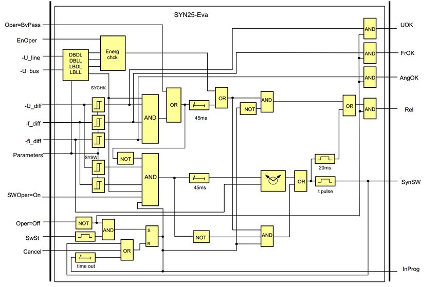
In the following figure is presented the operating logic of the synchrocheck function.
RelA
SwStA
CancelA SYN25_Eva
(aut) SynSWA
InProgA
UlineFour(3ph) UOKA
Ubus1Four FrOKA
Ubus2Four AngOKA
SYN25_Com
Bus Sel
VTS Blk
RelM
Bus1 VTS Blk
Bus2 VTS Blk
Blk SYN25_Eva
(man)
SynSWM
SwStM InProgM
CancelM UOKM
FrOKM
Parameters AngOKM
Figure 4-11: Operation logic of the synchrocheck function.
The synchro check/synchro switch function contains two kinds of software blocks:
• SYN25_Com is a common block for manual switching and automatic switching
• SYN25_EVA is an evaluation block, duplicated for manual switching and for
automatic switching
The SYN25_Com block selects the appropriate voltages for processing and calculates
the voltage difference, the frequency difference and the phase angle difference
between the selected voltages. The magnitude of the selected voltages is passed for
further evaluation.
These values are further processed by the evaluation software blocks. The function is
disabled if the binary input (Block) signal is TRUE. The activation of voltage
transformer supervision function of the line voltage blocks the operation (VTS Block).
The activation of voltage transformer supervision function of the selected bus section
blocks the operation (VTS Bus1 Block or VTS Bus2 Block).Instruction manual –AQ S391 bay control IED 27 (63)
SYN25_Com
-U_diff
UlineFour (3ph)
Calc -f_diff
Ubus1Four
U_bus
-fi_ diff
Ubus2Four
-U_bus
-U_line
BusSel
1000ms
100m
s Blk
VTS Blk OR
Bus1 VTS Blk
VTS
U_bus
Bus2 VTS Blk
Parameters
Figure 4-12: Synchrocheck common difference calculation function structure.
If the active bus section changes the function is dynamically blocked for 1000ms and
no release signal or switching command is generated. The processed line voltage is
selected based on the preset parameter (Voltage select). The choice is: L1-N, L2-N,
L3-N, L1-L2, L2-L3 or L3-L1. The parameter value must match the input voltages
received from the bus sections. The active bus section is selected by the input signal
(Bus select). If this signal is logic TRUE, then the voltage of Bus2 is selected for
evaluation.
The software block SYN25_Eva is applied separately for automatic and manual
commands. This separation allows the application to use different parameter values
for the two modes of operation.
The structure of the evaluation software block is shown in the following figure.Instruction manual –AQ S391 bay control IED 28 (63) Figure 4-13: Synchrocheck evaluation function structure. This evaluation software block is used for two purposes: for the automatic reclosing command (the signal names have the suffix “A”) and for the manual close request (the signal names have the suffix “M”). As the first step, based on the selected line voltage and bus voltage, the state of the required switching is decided (Dead bus-Dead line, Dead bus-Live line, Live bus-Dead line or Live bus- Live line). The parameters for decision are (U Live) and (U Dead). The parameters (Energizing Auto/Manual) enable the operation individually. The choice is: (Off, DeadBus LiveLine, LiveBus DeadLine, Any energ case). In simple energizing modes, no further checking is needed. This mode selection is bypassed if the parameter (Operation Auto/Manual) is set to “ByPass”. In this case the command is transmitted without any further checking. First, the function tries switching with synchro check. This is possible if: the voltage difference is within the defined limits (Udiff SynChk Auto/Manual)) the frequency difference is within the defined limits (FrDiff SynChk Auto) and the phase angle difference is within the defined limits (MaxPhaseDiff Auto/Manual)). If the conditions are fulfilled for at least 45 ms, then the function generates a release output signal (Release Auto/Manual). If the conditions for synchro check operation are not fulfilled and a close request is received as the input signal (SySwitch Auto/Manual), then synchro switching is
Instruction manual –AQ S391 bay control IED                                          29 (63)

attempted. This is possible if: the voltage difference is within the defined limits (Udiff
SynSW Auto /Manual)) the frequency difference is within the defined limits (FrDiff
SynSW Auto).

These parameters are independent of those for the synchro check function. If the
conditions for synchro check are not fulfilled and the conditions for synchro switch are
OK, then the relative rotation of the voltage vectors is monitored. The command is
generated before the synchronous position, taking the breaker closing time into
consideration (Breaker Time). The pulse duration is defined by the parameter (Close
Pulse). In case of slow rotation and if the vectors are for long time near-opposite
vector positions, no switching is possible, therefore the waiting time is limited by the
preset parameter (Max.Switch Time).

The progress is indicated by the output status signal (SynInProgr Auto/Manual). The
started command can be canceled using the input signal (Cancel Auto/Manual).

   Figure 4-14 The function block of the synchro check / synchro switch function
The binary input and output status signals of the dead line detection function are
listed in tables below.
Instruction manual –AQ S391 bay control IED                                               30 (63)

Table 4-15 The binary input signal of the synchro check / synchro switch function

 Binary status signal        Title              Explanation
                                                If this signal is logic TRUE, then the voltage
 SYN25_BusSel_GrO_           Bus Select         of Bus2 is selected for evaluation
                                                Blocking signal of the voltage transformer
                                                supervision function evaluating the line
 SYN25_VTSBlk_GrO_           VTS Block          voltage
                                                Blocking signal of the voltage transformer
                                                supervision function evaluating the Bus1
 SYN25_Bus1VTSBlk_GrO_       VTS Bus1 Block     voltage
                                                Blocking signal of the voltage transformer
                                                supervision function evaluating the Bus2
 SYN25_Bus2VTSBlk_GrO_       VTS Bus2 Block     voltage
                                                Switching request signal initiated by the
 SYN25_SwStA_GrO_            SySwitch Auto      automatic reclosing function
                                                Signal to interrupt (cancel) the automatic
 SYN25_CancelA_GrO_          Cancel Auto        switching procedure
 SYN25_Blk_GrO_              Block              Blocking signal of the function
                                                Switching request signal initiated by
 SYN25_SwStM_GrO_            SySwitch Manual    manual closing
                                                Signal to interrupt (cancel) the manual
 SYN25_CancelIM_GrO_         Cancel Manual      switching procedure
Instruction manual –AQ S391 bay control IED 31 (63)
Table 4-16 The binary output status signals of the synchro check / synchro switch
function
Binary status signal Title Explanation
Releasing the close command initiated by
SYN25_RelA_GrI_ Release Auto the automatic reclosing function
Switching procedure is in progress,
initiated by the automatic reclosing
SYN25_InProgA_GrI_ SynInProgr Auto function
The Voltage difference is appropriate for
SYN25_UOKA_GrI_ Udiff OK Auto automatic closing command
The frequency difference is appropriate
for automatic closing command, evaluated
SYN25_FrOKA_GrI_ FreqDiff OK Auto for synchro-check
The angle difference is appropriatefor
SYN25_AngOKA_GrI_ Angle OK Auto automatic closing command
Releasing the close command initiated by
SYN25_RelM_GrI_ Release Man manual closing request
Switching procedure is in progress,
SYN25_InProgM_GrI_ SynInProgr Man initiated by the manual closing command
The Voltage difference is appropriate for
SYN25_UOKM_GrI_ Udiff OK Man automatic closing command
The frequency difference is appropriate
for manual closing command, evaluated
SYN25_FrOKM_GrI_ FreqDiff OK Man for synchro-check
The angle difference is appropriatefor
SYN25_AngOKM_Grl_ Angle OK Man manual closing commandInstruction manual –AQ S391 bay control IED 32 (63)
Table 4-17 Setting parameters of the synchro check / synchro switch function
Parameter Setting value, range Description
and step
Voltage select L1-N Reference voltage selection. The function will monitor the
L2-N selected voltage for magnitude, frequency and angle
L3-N differences. Default setting is L1-N
L1-L2
L2-L3
L3-L1
U Live 60…110 % by step of Voltage setting limit for “Live Line” detection. When
1% measured voltage is above the setting value the line is
considered “Live”. Default setting is 70 %.
U Dead 10…60 % by step of Voltage setting limit for “Dead Line” detection. When
1% measured voltage is below the setting value the line is
considered “dead”. Default setting is 30 %.
Breaker Time 0…500 ms by step of Breaker operating time at closing. This parameter is used
1 ms for the synchro switch closing command compensation and
it describes the breaker travel time from open position to
closed position from the close command. Default setting is
80 ms.
Close Pulse 10…60000 ms by Close command pulse length. This setting defines the
step of 1 ms duration of close command from the IED to the circuit
breaker. Default setting is 1000 ms.
Max Switch 100…60000 ms by Maximum allowed switching time. In case synchro check
Time step of 1 ms conditions are not fulfilled and the rotation of the networks
is slow this parameter defines the maximum waiting time
after which the close command is failed. Default setting is
2000ms.
Operation On Operation mode for automatic switching. Selection can be
Auto Off automatic switching off, on or bypassed. If the Operation
ByPass Auto is set to “Off” automatic switch checking is disabled. If
selection is “ByPass” Automatic switching is enabled with
bypassing the bus and line energization status checking.
When the selection is “On” also the energization status of
bus and line are checked before processing the command.
Default setting is “On”
SynSW Auto On Automatic synchroswitching selection. Selection may be
Off enabled “On” or disabled “Off”. Default setting is Enabled
“On”.
Energizing Off Energizing mode of automatic synchroswitching. Selections
Auto DeadBus LiveLine consist of the monitoring of the energization status of the
LiveBus DeadLine bus and line. If the operation is wanted to be LiveBus
Any energ case LiveLine or DeadBus DeadLine the selection is “Any energ
case”. Default setting is DeadBus LiveLine.
Udiff SynChk 5…30 % by step of 1 Voltage difference checking of the automatic synchrocheck
Auto % mode. If the measured voltage difference is below this
setting the condition applies. Default setting is 10 %.
Udiff SynSW 5…30 % by step of 1 Voltage difference checking of the automatic synchroswitch
Auto % mode. If the measured voltage difference is below this
setting the condition applies. Default setting is 10 %.
MaxPhasediff 5…80 deg by step of Phase difference checking of the automatic synchroswitch
Auto 1 deg mode. If the measured phase difference is below this
setting the condition applies. Default setting is 20 deg.Instruction manual –AQ S391 bay control IED 33 (63)
FrDiff SynChk 0.02…0.50 Hz by Frequency difference checking of the automatic
Auto step of 0.01 Hz synchrocheck mode. If the measured phase difference is
below this setting the condition applies. Default setting is
0.02 Hz.
FrDiff SynSW 0.10…1.00 Hz by Frequency difference checking of the automatic
Auto step of 0.01 Hz synchroswitch mode. If the measured phase difference is
below this setting the condition applies. Default setting is
0.2 Hz.
Operation On Operation mode for manual switching. Selection can be
Man Off manual switching off, on or bypassed. If the Operation Man
ByPass is set to “Off” manual switch checking is disabled. If
selection is “ByPass” manual switching is enabled with
bypassing the bus and line energization status checking.
When the selection is “On” also the energization status of
bus and line are checked before processing the command.
Default setting is “On”
SynSW Man On Manual synchroswitching selection. Selection may be
Off enabled “On” or disabled “Off”. Default setting is Enabled
“On”.
Energizing Off Energizing mode of manual synchroswitching. Selections
Man DeadBus LiveLine consist of the monitoring of the energization status of the
LiveBus DeadLine bus and line. If the operation is wanted to be LiveBus
Any energ case LiveLine or DeadBus DeadLine the selection is “Any energ
case”. Default setting is DeadBus LiveLine.
Udiff SynChk 5…30 % by step of 1 Voltage difference checking of the manual synchrocheck
Man % mode. If the measured voltage difference is below this
setting the condition applies. Default setting is 10 %.
Udiff SynSW 5…30 % by step of 1 Voltage difference checking of the manual synchroswitch
Man % mode. If the measured voltage difference is below this
setting the condition applies. Default setting is 10 %.
MaxPhaseDiff 5…80 deg by step of Phase difference checking of the manual synchroswitch
Man 1 deg mode. If the measured phase difference is below this
setting the condition applies. Default setting is 20 deg.
FrDiff SynChk 0.02…0.50 Hz by Frequency difference checking of the manual synchrocheck
Man step of 0.01 Hz mode. If the measured phase difference is below this
setting the condition applies. Default setting is 0.02 Hz.
FrDiff SynSW 0.10…1.00 Hz by Frequency difference checking of the manual synchroswitch
Man step of 0.01 Hz mode. If the measured phase difference is below this
setting the condition applies. Default setting is 0.2 Hz.Instruction manual –AQ S391 bay control IED 34 (63) 5 APPLICATION EXAMPLES 5.1 ONE AND HALF CIRCUIT BREAKER CONFIGURATION
Instruction manual –AQ S391 bay control IED                       35 (63)

5.2 IED IO POSITIONS IN ONE AND HALF CIRCUIT BREAKER CONFIGURATION
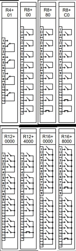
Instruction manual –AQ S391 bay control IED                                         36 (63)

6 CONSTRUCTIONS AND INSTALLATION
   The Arcteq AQ-S391 bay control IED consists of hardware modules. Due to modular
   structure optional positions for the slots can be user defined in the ordering of the IED
   to include I/O modules and other types of additional modules. An example module
   arrangement configuration of the AQS391 is shown in the figure below. Visit
   https://configurator.arcteq.fi/ to see all of the available options.

   Figure 6-1: An example module arrangement configuration of the AQ-S391 IED.

   Example above presents a simple hardware configuration with redundant power
   supplies (PS+2103), signaling binary outputs (R16+0000), binary input cards
   (O16+1101 and O8+1101) and 100Base-FX Ethernet MM/LC communication card
   (CPU+6601).

   Figure 6-2: An example module arrangement configuration of the AQ-S391 IED.

   Example above presents a simple hardware configuration with redundant power
   supplies (PS+2103), trip contacts (TRIP+2101), signaling binary outputs (R12+0000),
Instruction manual –AQ S391 bay control IED                        37 (63)

binary input cards (O16+1101 and O8+1101) and 100Base-FX Ethernet MM/LC
communication card (CPU+6601).

Following chapters describe the cards in more detail.
Instruction manual –AQ S391 bay control IED                                    38 (63)

6.1 CPU MODULE

  Figure 3 Communication card with 100Base-FX Ethernet MM/LC 1300 nm, 50/62.5/125 μm
  connector, (up to 2 km) fiber.

  The CPU module contains all the protection, control and communication functions of
  the AQ-300 device. Dual 500 MHz high-performance Analog Devices Blackfin
  processors separate relay functions (RDSP) from communication and HMI functions
  (CDSP). Reliable communication between processors is performed via high-speed
  synchronous serial internal bus (SPORT). Each processor has its own operative
  memory such as SDRAM and non-volatile flash memories for configuration, parameter
  and firmware storage. The firmwares are stored in a dedicated flash memory
  independent from the disturbance recorder and event storage. CDSP’s operating
  system (uClinux) utilizes a robust JFFS flash file system, which enables fail-safe
  operation and the storage of disturbance record files, configuration and parameters.

  The RDSP core runs at 500 MHz and its external bus speed is 125 MHz. The
  backplane data speed is limited to approx. 20 MHz, which is more than enough for
  module data throughput. An additional logic element (CPLD and SRAM) is used as a
  bridge between the RDSP and the backplane. The CPLD collects analogue samples
  from CT/VT modules and also controls signaling outputs and inputs.
Instruction manual –AQ S391 bay control IED                                      39 (63)

After power-up the RDSP processor starts up with the previously saved configuration
and parameters. Generally, the power-up procedure for the RDSP and relay functions
takes only a few seconds. That is to say, it is ready to trip within this time. CDSP’s
start-up procedure is longer because its operating system needs time to build its file
system, initializing user applications such as HMI functions and the IEC61850
software stack.

HMI and communication tasks

   •   Embedded WEB-server:
         o Firmware upgrade possibility
          o   Modification of user parameters
          o   Events list and disturbance records
          o   Password management
          o   Online data measurement
          o   Commands
           o Administrative tasks
   •   Front panel TFT display handling: the interactive menu set is available through
       the TFT and the touchscreen interface
   •   User keys: capacitive touch keys on front panel
   •   The built-in 5-port Ethernet switch allows AQ-300 to connect to IP/Ethernet-
       based networks. The following Ethernet ports are available:
          o Station bus (100Base-FX Ethernet) SBW
          o Redundant station bus (100Base-FX Ethernet) SBR
          o Process bus (100Base-FX Ethernet)
          o EOB or EOB2 (Ethernet Over Board) or RJ-45 Ethernet user interface on
              front panel
          o Optional 10/100Base-T port via RJ-45 connector
   •   PRP/HSR     seamless redundancy for          Ethernet networking (100Base-FX
       Ethernet)
   •   Other communication:
          o RS422/RS485 interfaces (galvanic interface to support legacy or other
              serial protocols, ASIF)
          o   Plastic or glass fiber interfaces to support legacy protocols, ASIF
          o   Proprietary process bus communication controller on COM+ module
          o   Telecommunication interfaces: G.703, IEEE C37.94
Instruction manual –AQ S391 bay control IED 40 (63)
6.2 POWER SUPPLY MODULE
The power supply module converts primary AC and/or DC voltage to required system
voltages. In most applications, one power supply module is sufficient to provide the
required power to the system. Redundant power supply modules extend system
availability in case of the outage of any power source.
IMPORTANT: Depending on the hardware configuration, the power consumption of
the devices can be different. We reserve the right to make the decision about which
PS+ module must be used. For most applications where the power consumption does
not reach 30 W we use one of our 4 HP wide PS+ modules.
Figure 4 Power supply module connections
Module type PS+2101
Nominal voltage 110 V DC / 220 V DC
Input voltage range 88 - 264 V DC
80 – 250 V AC
Nominal power 20 W
Input voltage interruption time (at Min. 100ms in the specified input
nominal load) voltage range
Internal fuse 3.15A/250V
Connector type Power connector:Instruction manual –AQ S391 bay control IED 41 (63)
Receptacle: Weidmüller SLA 2/90
Plug: Weidmüller BLA 2/180
Fault relay connector:
Receptacle: Weidmüller SLA 3/90
Plug: Weidmüller BLA 3/180
Main features:
• Fault relay contacts (NC and NO): device fault contact and also assignable to
user functions. All the three relay contact points are accessible to users.
• Redundant applications (nominal power and reliability can be increased by
using parallel power supplies)
• On-board self-supervisory circuits: temperature and voltage monitors
• Short-circuit-protected outputs
• Efficiency: > 70 %, power consumption = nominal power / efficiency
• Passive heatsink
• Early power failure indication signals to the CPU the possibility of power
outage, thus the CPU has enough time to save the necessary data to non-
volatile memory
• Inrush current (until 0.1 s): < 10 A for all types excluding PS+4401 which has <
21 A inrush current.
• Common features for internal fuses:
o 5 mm x 20 mm (0.20" x 0.79")
o TT characteristics (very inverse time-lag)
o 35 A @ 250 V AC rated breaking capacity
• Recommended external protection: miniature circuit breaker, 6 A (C char.)Instruction manual –AQ S391 bay control IED 42 (63)
6.3 BINARY INPUT MODULES
The inputs are galvanic isolated and the module converts high-voltage signals to the
voltage level and format of the internal circuits.
Module type O8+2401 O8+4801 O8+1101 O8+2201
Number of 8 8 8 8
channels
Time Configured Configured Configured Configured
synchronization by AQtivate by AQtivate by AQtivate by AQtivate
Rated voltage 24 V 48 V 110 V 220 V
Thermal 72 V 100 V 250 V 320 V
withstand
voltage
Clamp voltage Falling 0.64 Falling 0.64 Falling 0.64 Falling 0.64
Un Un Un Un
Rising 0.8 Rising 0.8 Rising 0.8 Rising 0.8
Un Un Un Un
Grounding independent independent independent independent
groups
Connector type Receptacle: Weidmüller SLA 16/90
Plug: Weidmüller BLA 16/180
Module type O12+2401 O12+4801 O12+1101 O12+2201
Number of 12 12 12 12
channels
Time Configured Configured Configured Configured
synchronization by AQtivate by AQtivate by AQtivate by AQtivate
Rated voltage 24 V 48 V 110 V 220 V
Thermal 72 V 72 V 250 V 320 V
withstand
voltage
Clamp voltage Falling 0.64 Falling 0.64 Falling 0.64 Falling 0.64
Un Un Un Un
Rising 0.8 Rising 0.8 Rising 0.8 Rising 0.8
Un Un Un Un
Grounding 4x3 4x3 4x3 4x3
groups common common common common
ground ground ground groundYou can also read