PD PA AP Maxum II Reference Manual - Maxum II - Industry Support Siemens
←
→
Page content transcription
If your browser does not render page correctly, please read the page content below
Analyzer Overview            1
                                                    Electronic Compartment
                                                    Component Descriptions and   2
                                                    Maintenance Procedures

Maxum II                                            Specifications               3

PD PA AP
Maxum II Reference Manual

Manual

Product Descriptions and Maintenance for Maxum II
Airless/Airbath Model Gas Chormatograph

7/2017
2000596-001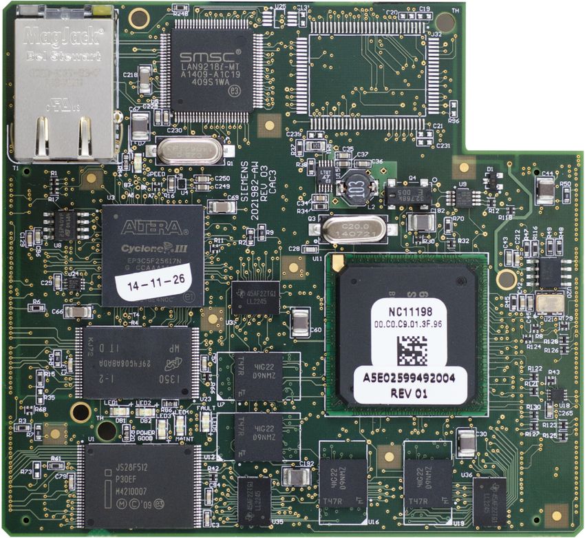
Legal information
Warning notice system
             This manual contains notices you have to observe in order to ensure your personal safety, as well as to prevent
             damage to property. The notices referring to your personal safety are highlighted in the manual by a safety alert
             symbol, notices referring only to property damage have no safety alert symbol. These notices shown below are
             graded according to the degree of danger.

                    DANGER
              indicates that death or severe personal injury will result if proper precautions are not taken.

                    WARNING
              indicates that death or severe personal injury may result if proper precautions are not taken.

                    CAUTION
              indicates that minor personal injury can result if proper precautions are not taken.

              NOTICE
              indicates that property damage can result if proper precautions are not taken.
             If more than one degree of danger is present, the warning notice representing the highest degree of danger will be
             used. A notice warning of injury to persons with a safety alert symbol may also include a warning relating to property
             damage.
Qualified Personnel
             The product/system described in this documentation may be operated only by personnel qualified for the specific
             task in accordance with the relevant documentation, in particular its warning notices and safety instructions. Qualified
             personnel are those who, based on their training and experience, are capable of identifying risks and avoiding
             potential hazards when working with these products/systems.
Proper use of Siemens products
             Note the following:

                    WARNING
              Siemens products may only be used for the applications described in the catalog and in the relevant technical
              documentation. If products and components from other manufacturers are used, these must be recommended or
              approved by Siemens. Proper transport, storage, installation, assembly, commissioning, operation and
              maintenance are required to ensure that the products operate safely and without any problems. The permissible
              ambient conditions must be complied with. The information in the relevant documentation must be observed.

Trademarks
             All names identified by ® are registered trademarks of Siemens AG. The remaining trademarks in this publication
             may be trademarks whose use by third parties for their own purposes could violate the rights of the owner.
Disclaimer of Liability
             We have reviewed the contents of this publication to ensure consistency with the hardware and software described.
             Since variance cannot be precluded entirely, we cannot guarantee full consistency. However, the information in
             this publication is reviewed regularly and any necessary corrections are included in subsequent editions.

             Siemens AG                               Document order number: 2000596-001                 Copyright © Siemens AG 2007 - 2017.
             Division Process Industries and Drives   Ⓟ 08/2017 Subject to change                        All rights reserved
             Postfach 48 48
             90026 NÜRNBERG
             GERMANY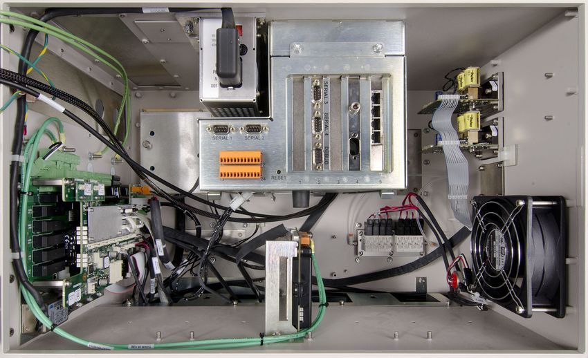
Table of contents

1      Analyzer Overview........................................................................................................................................7
       1.1               Introduction..............................................................................................................................7
       1.2               Analyzer Specific Documents..................................................................................................8
       1.3               Parts of the Maxum II...............................................................................................................8
       1.4               Isothermal Oven.......................................................................................................................9
       1.5               Switching and Sampling Valves.............................................................................................10
       1.6               Operator Controls...................................................................................................................11
2      Electronic Compartment Component Descriptions and Maintenance Procedures.....................................13
       2.1               Power Supplies......................................................................................................................13
       2.1.1             Power System Module...........................................................................................................13
       2.1.2             Replacement Procedure........................................................................................................15
       2.2               Power Entry and Control Module...........................................................................................18
       2.2.1             PECM Overview.....................................................................................................................18
       2.2.2             Feature Additions...................................................................................................................19
       2.2.3             PECM Functions....................................................................................................................20
       2.2.3.1           AC Input and Distribution.......................................................................................................20
       2.2.3.2           Oven Temperature Control....................................................................................................21
       2.2.3.3           Communication and Power Distribution.................................................................................22
       2.2.3.4           Onboard Solid State Relays...................................................................................................23
       2.2.3.5           Oven Functions......................................................................................................................24
       2.2.3.6           Electronic Enclosure Environment.........................................................................................26
       2.2.4             Replacement Procedure........................................................................................................28
       2.2.4.1           Troubleshooting.....................................................................................................................28
       2.2.4.2           Removing The PECM............................................................................................................30
       2.2.4.3           Installing The New PECM......................................................................................................31
       2.3               System Controller Version 2.1 (SYSCON2.1)........................................................................32
       2.3.1             Description.............................................................................................................................32
       2.3.2             Mechanical.............................................................................................................................33
       2.3.3             SYSCON2.1 Components......................................................................................................34
       2.3.3.1           Communication and Control Board (CAC3)...........................................................................34
       2.3.3.2           CAC3 Status Indicator LEDs..................................................................................................35
       2.3.3.3           SIB.........................................................................................................................................36
       2.3.3.4           Ethernet Port Expansion........................................................................................................44
       2.3.4             Maintenance Overview...........................................................................................................48
       2.3.5             Service Procedures................................................................................................................48
       2.3.6             Replacing the Lithium Battery on the SYSCON Module Introduction....................................53
       2.3.7             Procedure...............................................................................................................................53
       2.4               Analog and Digital IO.............................................................................................................54
       2.4.1             IO Card Common Features....................................................................................................55
       2.4.2             Digital IO Card........................................................................................................................58
       2.4.3             Analog IO Board.....................................................................................................................59

Maxum II Reference Manual
Manual, 7/2017, 2000596-001                                                                                                                                          3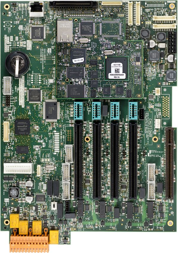
Table of contents

      2.4.4              Analog and Digital IO Board...................................................................................................60
      2.5                Detector Personality Modules................................................................................................61
      2.5.1              DPM Types............................................................................................................................61
      2.5.2              Base3 Detector Personality Module (DPM)...........................................................................61
      2.5.3              Replacing a Base3DPM.........................................................................................................66
      2.5.4              Intrinsically-Safe Thermal Conductivity DPM (IS-TCD3)........................................................68
      2.5.5              Replacing an IS-TCD DPM....................................................................................................70
      2.5.6              Replacing a TC-DPM.............................................................................................................71
      2.6                Sensor Near Electronics (SNE) Software..............................................................................72
      2.7                Solid State Relay Module.......................................................................................................74
      2.8                Solenoid Valves.....................................................................................................................76
      2.8.1              Solenoid Valve Control Module (SVCM)................................................................................76
      2.8.2              Replacing a Solenoid Valve...................................................................................................80
      2.9                Electronic Pressure Control Module.......................................................................................81
      2.9.1              EPC Module Description........................................................................................................81
      2.9.2              Replacing an EPC Module.....................................................................................................83
      2.10               Color Touchscreen.................................................................................................................85
      2.10.1             Description.............................................................................................................................85
      2.10.2             Maintenance Overview...........................................................................................................85
      2.10.3             Replacement Procedures.......................................................................................................86
3     Specifications.............................................................................................................................................93
      Index...........................................................................................................................................................99

                                                                                                                                    Maxum II Reference Manual
4                                                                                                                                  Manual, 7/2017, 2000596-001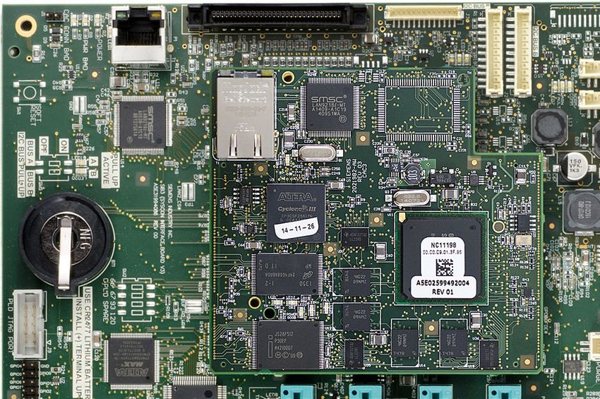
WARNING
                      Do not connect analyzer to the internet.
                      This equipment must not be connected to the internet except by a secure connection using
                      a network security appliance administered by qualified IT personnel.
                      Failure to implement robust network security may expose your company to internet hacking
                      attacks that could result in theft or loss of sensitive data, equipment damage, serious injury
                      or death.

Maxum II Reference Manual
Manual, 7/2017, 2000596-001                                                                                            5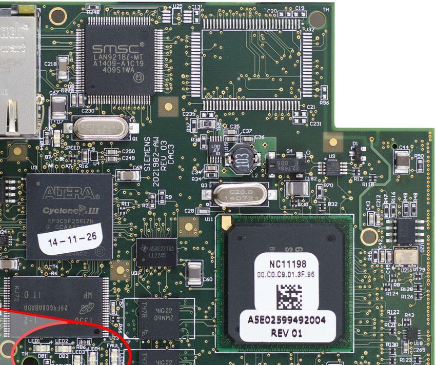
Maxum II Reference Manual
6   Manual, 7/2017, 2000596-001
Analyzer Overview                                                                                          1
1.1              Introduction

                     The Maxum edition II system, also called the “Maxum II”, represents a significant advance in
                     process chromatography. The Maxum II combines the best of the Siemens Advance Maxum
                     and PGC 302 gas chromatographs into a single platform analyzer. From oven and electronic
                     components to software and communication networks, the system is modular. Pre-configured
                     application modules are available for many common measurements.
                     A Maxum II system offers a wide range of detector modules including Thermal Conductivity,
                     Flame Ionization, Flame Photometric, and the Pulsed Discharge Detector (which can operate
                     in Helium Ionization, Photoionization, and Electron Capture modes). All detector modules are
                     available for both air bath and airless ovens. The Maxum II oven is designed so it can be
                     divided into two independently heated isothermal ovens for parallel chromatography
                     applications.
                     The Maxum II Maintenance Panel provides maintenance personnel with access to all
                     maintenance functions and data. In addition, the Maintenance Panel displays both real time
                     and archived chromatograms. A PC-based network workstation runs the Gas Chromatograph
                     Portal software.

Analyzer Specific Documents
                     Included with each analyzer is a custom documentation-drawing package. This package
                     provides drawings and information pertinent only to a specific analyzer. Contents of this
                     package are application-dependent and vary for each analyzer. Typical drawings included are:

                     ● System Block and Utility Requirements   ●      Applicable Wiring Diagrams
                     ● System Outline and Dimensional Drawings ●      Oven Plumbing Diagram - Sensor Near
                     ● Sampling System - Plumbing and Spare           Electronics
                       Parts List                              ●      Recommended Spare Parts - Analyzer
                     ● Sampling System Dimensional Diagram     ●      Manufacturing Test Charts
                     ● Sampling Probe                          ●      Stream Composition Data
                     ● Electronic Enclosure Section - Internal ●      Database
                       Layout

Maxum II Reference Manual
Manual, 7/2017, 2000596-001                                                                                     7
Analyzer Overview
1.3 Parts of the Maxum II

1.2            Analyzer Specific Documents
                    Included with each analyzer is a custom documentation-drawing package. This package
                    provides drawings and information pertinent only to a specific analyzer. Contents of this
                    package are application-dependent and vary for each analyzer. Typical drawings included are:

                    ● System Block and Utility Requirements     ●            Applicable Wiring Diagrams
                    ● System Outline and Dimensional Drawings ●              Oven Plumbing Diagram - Sensor Near
                    ● Sampling System - Plumbing and Spare                   Electronics
                      Parts List                                ●            Recommended Spare Parts - Analyzer
                    ● Sampling System Dimensional Diagram       ●            Manufacturing Test Charts
                    ● Sampling Probe                            ●            Stream Composition Data
                    ● Electronics Compartment - Internal Layout ●            Database

1.3            Parts of the Maxum II

Overview
                    The Maxum II Gas Chromatagraph is completely enclosed in an air-purgable, metal cabinet
                    with hinged doors. Mounted above the isothermal oven is the electronics enclosure and
                    regulator panel. The analyzer may be mounted on a wall, in a rack or on a floor stand.

                       Electronics                                                       Regulator
                       Enclosure                                                          Panel

                         Color
                      Touchscreen
                                                                                         Detector
                                                                                       Compartment

                      Isothermal
                         Oven

                    Figure 1-1       Maxum II External Component Locations

                                                                                               Maxum II Reference Manual
8                                                                                             Manual, 7/2017, 2000596-001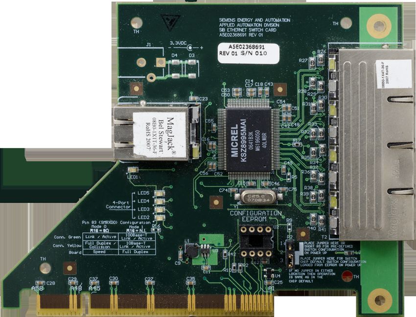
Analyzer Overview
                                                                                                    1.4 Isothermal Oven

Electronics Enclosure
                     The Electronics Enclosure houses all the electronics and pneumatic modules required for
                     performing all temperature, valve control and analysis functions. The Electronics Enclosure
                     modules are interconnected using simple cable connections made to each module. All modules
                     can be easily removed and replaced. The Maxum II software recognizes each Maxum II’s
                     application, hardware components and network configurations.

                    International               System Controller (SYSCON) For Communications,
                    Power Supply                  Human Interface and Database Management.

   Solid
   State
  Relay                                                                           8-Channel Electronic
  Module                                                                          Pressure Control. Up
                                                                                    To 4 Modules. 2
                                                                                   Channels Each For
                                                                                   Control Of Carrier
                                                                                     Gas Pressure

   Power
   Entry
  Control
  Module
  (PECM)

                                                     Detector Personality Module (DPM)
                                                        for Detector Data Acquisition

Figure 1-2    Electronics Enclosure Component Locations

Regulator Panel
                     The regulator panel contains space for seven gauges and regulators. The base Maxum II
                     comes with two standard regulators and an electronics enclosure fast purge. See the custom
                     documentation drawing package that was shipped with the analyzer to see which gauges and
                     regulators are mounted on the analyzer.

1.4              Isothermal Oven

                     The Maxum ll has a wide variety of isothermal oven configurations. Both air bath and airless
                     ovens are available. All air bath configurations are available with Vortex cooling for sub-
                     ambient temperature operation. A program temperature oven option is available for Maxum II
                     applications where isothermal, multi-dimensional chromatography is not practical. Typically
                     the program temperature Maxum II is used for Motor Gasoline (ASTM 3710) & Simulated
                     Distillation (ASTM 2887) applications.

Maxum II Reference Manual
Manual, 7/2017, 2000596-001                                                                                             9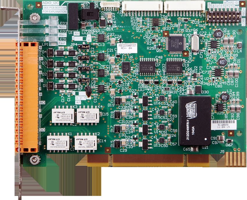
Analyzer Overview
1.5 Switching and Sampling Valves

                     Oven Configurations

Split Airless Oven
                                                             Single Air Bath Oven

Fully independent dual ovens with separate oven doors. The
                                                             Large, spacious compartment for complex applications and
oven uses cartridge heaters in each side to heat the oven
                                                             for ease of maintenance.
enclosure and its components.

Programmed Temperature Air Bath Oven

                                                             Dual Air Bath Split Oven
Provides a programmed temperature gradient for applica‐
tions requiring this.
                                                             Split Oven Configuration: Offers two temperature zones for
                                                             one or more applications.

1.5              Switching and Sampling Valves

Application             Model         Description
Vapor Samples           Model 50      10-port non-plunger diaphragm. Contains no moving parts. It will operate over 10
                                      million cycles on clean samples and can operate on carrier gas or other bottled inert
                                      gas with negligible consumption. It does the work of two Model 11 valves and is half
                                      the size.
Vapor or Liquid Sam‐    Model 11      6-port diaphragm–plunger valve high reliability and life. Used as a liquid or vapor
ples                    and Model     sample valve, column switching valve or a column back flush valve. Process lines,
                        11 LDV        columns and valve-to-valve tubes can be connected directly to the caps of the Model
                                      11 LDV (Low Dead Volume) version of the valve.

                                                                                                  Maxum II Reference Manual
10                                                                                               Manual, 7/2017, 2000596-001
Analyzer Overview
1.6 Operator Controls
Vapor or High Pres‐ Model 20 The air-pressure actuated, diaphragm valve provides uniform sample volume, low
sure Liquid Samples internal volume, high pressure up to 1500 psi, 10350 kPa, fast switching (millisec‐
onds), reliability, and durability. It functions equally well as a liquid or vapor sample
valve, column switching valve, or column back flush valve.
Liquid Sample LIV The liquid injection valve can be used to automatically inject a constant quantity of
liquid sample followed by fast, complete vaporization. Small gas quantities can also
be injected using the valve.
Vapor Valveless The device has no parts to fail or wear out and exhibits essentially zero dead volume
Live Column for fast column switching and sample injection with capillary columns.
Switching
1.6 Operator Controls
Color Touchscreen
The color touchscreen displays all mainte‐
nance functions and data in a graphical dis‐
play. In addition it can also display both real-
time and stored chromatograms. The stored
chromatograms include voltages and cycle
times for future comparison as well as zoom
and pan features. Operational and routine
maintenance tasks for the analyer can be per‐
formed from the color touchscreen interactive
display screens and menus. System security
is assured with multiple levels of password
protection for all analyzer-operating func‐
tions.
A color touchscreen emulator (also called a Human Machine Interface, or HMI, emulator) is
available from the Maxum Gas Chromatograph Portal (GCP) software. This emulator allows
a user to perform color touchscreen tasks without being located at the unit.
Status LEDs
Purge (Flashing Red) Purge pressure lost
Fault (Red) "Failure" status is active
Warning (Yellow) "Maintenance request" status signal is active
Power (Green) 24 V power supply is on
All LEDs are on during power-up boot.
Maxum II Reference Manual
Manual, 7/2017, 2000596-001 11Analyzer Overview
1.6 Operator Controls
Workstation
The Maxum II uses a PC based network
workstation for programming and data
processing. Analyzers can be program‐
med and monitored from a single location,
and, like the color touchscreen, the work‐
station includes graphical displays for op‐
eration, maintenance, and diagnostics. It
also supports PC printers to print chroma‐
tograms and alarm logs in order to meet
record keeping requirements.
The Maxum II workstation software, Gas Chromatograph Portal (GCP), is designed for PCs
with Microsoft® Windows operating systems. PC workstations can be connected through
existing LANs for wide access to monitoring or maintenance tasks. The graphical interface
recognizes and displays all network hardware. The system monitors the alarm status of all
analyzers connected to the network to centralize system maintenance. More information can
be found in the GCP Help Manual.
Chromatography Software
EZChrom© industry specific software is incorporated in the GCP software. This is a laboratory
quality application builder developed by Scientific Software, Inc. and includes custom features
for the Maxum II. Using EZChrom, it is possible to set up methods and component peak
identification. More information can be found in the Release Notes file supplied with the
EZChrom software (under the Maxum EZChrom directory).
EZChrom allows a user to choose the best peak gating and basing methods automatically. It
is also possible to:
● Re-process captured chromatograms with different methods
● Measure unknown component peaks automatically
● Record multiple detector measurements simultaneously.
Maxum II Reference Manual
12 Manual, 7/2017, 2000596-001Electronic Compartment Component Descriptions and
Maintenance Procedures 2
2.1 Power Supplies
2.1.1 Power System Module
Overview
The Power System Module (PSM) is a 110/230 VAC switching power supply that provides 24
VDC operating system voltages. It also provides 110/220 VAC conditioning. The 24 VDC power
supply provides high speed switching with power factor correction and universal input. The
PSM is a stand-alone system consisting of a power supply, filtering, circuit fuse protection and
a power monitor board.
Line Voltage Selector Switch
Power Fuse Holder
System
Module
Figure 2-1 Power System Module Location in EC
AC Line Input
AC power input to the power supply is from the Power Entry Control Module. A line cord from
the PECM plugs into the front AC receptacle of the power supply. A primary Line Voltage
Selector selector switch (located above the AC receptacle) must be set to match the primary
AC voltage input from the Power Entry Control Module.
Maxum II Reference Manual
Manual, 7/2017, 2000596-001 13Electronic Compartment Component Descriptions and Maintenance Procedures
2.1 Power Supplies
Output Connections
Output 24 VDC is supplied to components within the Maxum II via a cable harness that exits
the backside of the PSM. The cable terminates in quick disconnect connectors. Typically, a
white connector supplies 24 volts to the SYSCON2.1 cage and an orange connector supplies
24 volts to the PECM, where it is distributed to various modules in the EC. DC/DC converters
in the modules generate the other voltage levels needed by various circuits.
Fuse Replacement
The Power System Module is equipped with a fuse (Siemens Part Number A6X19905350).
This fuse is located on the front of the PSM just above the power cord plug. The fuse is a 250
V, 4.0 A, “slow-acting” type. Although this fuse rarely fails, replacement is simple (disconnect
power to the analyzer first). To remove the fuse, unplug the power cable that comes from the
PECM. Access the fuse by removing the fuse cap with a large blunt screwdriver.
Specifications
Voltage Range 115 VAC (85 to 140 VAC), 230 VAC (185 to 264 VAC)
Line Frequency Range 47 to 63 Hz
Nominal Input Current 2 amp @ 115 VAC, 1 amp @ 230 VAC
Nominal Output Voltage 24 VDC ±3%, 1% ripple plus noise at a bandwidth of 30 MHz
Nominal Output Current 6 A @ < 104°F (40°C)
4 A @ 104° to 150°F (40° to 70° C)
Static Load 0.2 A; 0.0 A open circuit permitted
Dynamic Load Between 0.2 A to 3 A in the load range. A maximum load of 2 A at 1.8 kHz is
switched. Switching is controlled by pulse width. Precision range is not exceeded
in this operational mode.
Overcurrent Cutoff Cutoff starts at 6.4 to 7.5 amps. When current drops, device switches on.
Overvoltage Cutoff Cutoff starts at 27 to 31 VDC. When voltage drops, device switches on.
Overtemperature Cutoff After temperature decreases to specified tolerance, device switches on.
Power Fail Transitions Occurs 20 ms after a primary power failure. Should a power failure occur, a low
20 ms signal is generated.
Electric Isolation Input/Output: 3.7 kV
Dimensions Length: 10.24 inches (260 mm)
Width: 2.36 inches (60 mm)
Depth: 3.54 inches (90 mm)
Cooling Convection and conduction through aluminum mounting plate.
Output Wiring Cable harness
Maxum II Reference Manual
14 Manual, 7/2017, 2000596-001Electronic Compartment Component Descriptions and Maintenance Procedures
2.1 Power Supplies
2.1.2 Replacement Procedure
Power Supply Location
Note
This procedure assumes that power is off in the analyzer.
The 24V power supply is easily accessed at the top of the electronics enclosure.
Replacement Steps
WARNING
Voltage dangerous to life exists in the electronics enclosure. Failure to follow proper safety
procedures may result in injury or death.
Turn off line votage to the analyzer before disassembling power-supply components. Even
though nothing appears to be operating, AC voltage can still be present on many of the
components in the enclosure.
NOTICE
Obtain all permits that may be required to perform this work.
Observe local codes and obtain any required permits before starting the work.
The power supply has an integral bracket that slips under flanges in the top of the enclosure
on the right side, and by two muts on threaded studs on the left side. Slots in the bracket allow
removing the supply without completely removing the nuts.
2
1
3 4 6
5
7 7
A. B. C.
Figure 2-2 Removing the Power Supply Module
Maxum II Reference Manual
Manual, 7/2017, 2000596-001 15Electronic Compartment Component Descriptions and Maintenance Procedures
2.1 Power Supplies
1. Ensure that power has been disconnected from the analyzer.
2. Open the electronics enclosure door.
3. Unplug SYSCON power cable from the bottom of the SYSCON cage.
4. Unplug the PECM 24V cable.
5. Loosen nuts (1 in photo A above)
6. Slide the power supply forward enough to disengage the power-supply tabs from enclosure
tabs as shown in photo below. (2 in photo A above)
7. Tilt the power supply clockwise to allow the tabs to clear the flanges. (3 in photo A above)
8. Drop the power supply off the nuts. (4 and 5 in photo B above)
9. Before completely removing the supply, unplug the safety ground wire from the spae lug
on the back of the enclosure. (See 7 in the photo C Removing the Power Supply Module
above.)
10.Slide the power supply out of encloure. (6 in photo B above)
Mo
un
tin
g fla
n ge
so
ni
ns
ide
top
of
en
cl o
su
re
Line-voltage
To PECM power connector To safety
selector switch
ground lug
on back wall
Fuse holder
To SYSCON
power connector Line-cord connector
on bottom-left of cage
Figure 2-3 Power Supply Module Details
Reinstalling the power supply
The new supply is installed using the steps in reverse order. It may be necessary to slightly
bend the flange edges down to allow the supply bracket to engage the flanges. See C in the
photo Removing the Power Supply Module above.
Maxum II Reference Manual
16 Manual, 7/2017, 2000596-001Electronic Compartment Component Descriptions and Maintenance Procedures
2.1 Power Supplies
Note
Verify proper position of line-voltage selector switch and fuse value. Incorrect settings can
damage the equipment.
See the information packet that was shipped with the analyzer for information on the individual
analyzer.
Maxum II Reference Manual
Manual, 7/2017, 2000596-001 17Electronic Compartment Component Descriptions and Maintenance Procedures
2.2 Power Entry and Control Module
2.2 Power Entry and Control Module
2.2.1 PECM Overview
Overview
The PECM3-CTL board mounts on the PECM-SSR board. This assembly provides a variety
of power and control functions. The connections are shown below.
AC in MWH out
LWH1 - LWH5
out HWH SSR
power out
Optional
UPS input Purge Air
for 24vdc Switch
supply
24v in
Fan
HWH SSR
power
control out
Temp RTD in
F1
u les
I2C bus
mo d t
F5
TL/
OT
tr o l ou MW
H Air bath heater
on in
F2 Hc trol monitor in
cov
er) H W H co n Solenoid
i th out HW
(w control out
F4 ver)
t co
w i th ou
( Atmospheric
F3
pressure sensor
PECM-SSR Board i n
on trol Purge disable jumper
WHc
Filtered H/M Purge signal out
LW
AC out I2C bus (Ribbon-cable
to 24v connector to
supply L1 MMI PECM-SSR)
PECM3-CTRL Board LED out
Figure 2-4 PECM3 I/O Connections
The PECM3 assembly part number is 2021828-002. An upgrade kit, part number 2022019-001
is available to replace earlier units.
Maxum II Reference Manual
18 Manual, 7/2017, 2000596-001Electronic Compartment Component Descriptions and Maintenance Procedures
2.2 Power Entry and Control Module
2.2.2 Feature Additions
Improvements in PECM3-CTL from PECM-CTL
● Seven I2C connectors are provided compared to 4 on the previous PECM-CTL, eliminating
the need for a Wiring Distribution Board (WDB).
● An Atmospheric pressure sensor has been added.
Improvements In PECM2 Assembly from Original PECM
The PECM design has changed since its original release. The newest version of this part is
also used as the spare-part replacement for the previous version. The original PECM was a
single electronic circuit board with a metal protective shield. It provided connection points for
the electrical power coming into the Maxum GC and mounted low power electrical relays which
could switch power to any electrical heater with a power rating of less than 200 watts.
The newest version of the module, PECM2, is a two part circuit board. One part connects the
electrical power. The other part includes certain electronic circuits. Key features of the newer
design are:
● Easy access (no cover)
● Two on-board temperature control circuits. May allow elimination of a DPM that is only used
for temperature control, such as for heated valves or the methanator.
● Additional medium-wattage heater circuit
● Four connectors providing I2C and 24VDC power distribution have been added. This
replaces some of the functions of the Wiring Distribution Board (WDB).
● Includes solenoid valve control which eliminates the need for individual SVCM controller
boards. When converting an older analyzer and eliminating original SVCM controller
boards, additional long cables are required.
● Improved low-profile fuse holders
● LED indicators for air pressure switch on air-bath heater circuits
● Built-in provision for connection of Uninterruptible Power Supply (UPS) for 24VDC circuits.
The heaters are powered through different connectors to minimize the loading of the AC
power needed for running the 24VDC circuits.
Maxum II Reference Manual
Manual, 7/2017, 2000596-001 19Electronic Compartment Component Descriptions and Maintenance Procedures
2.2 Power Entry and Control Module
2.2.3 PECM Functions
2.2.3.1 AC Input and Distribution
AC mains power is wired to TB1 and TB2. TB10 is an optional connection for an uninterruptable
power supply for the 24 V power supply output, as shown in the diagram below.
Note
The power switching circuit is designed for either 115 VAC or 230 VAC. For safety reasons,
the PECM is not designed to convert DC to AC. Attempted operation from a DC source will
damage or destroy the PECM. To generate and control 115 VAC from a DC voltage system,
the customer must use components external to the PECM.
TB10* TB1 TB2
*TB10 parallel-connected
to TB1 if UPS is not used
HN HNG 1 HNG
3
2
1
2
3
2
1
N1
N2
L1
L2
Filtered AC
F3
3A
Holder
J1 Low Wattage
Hot
H 1 Heater Relays 1- 5
Hot
G 2
N 3 F4 10A
AC Filter Plug AC Chassis Medium Wattage
(for 24V supply) Ground Heater Relays
Hot
F5 6A
Hot Hot
F1
Holder
Holder
F2
16A 16A
ABH2 ABH1
TB9
1
2
3
4
Air Bath Heater Power
Figure 2-5 PECM AC Power Distribution
Maxum II Reference Manual
20 Manual, 7/2017, 2000596-001Electronic Compartment Component Descriptions and Maintenance Procedures
2.2 Power Entry and Control Module
Fuses
Circuit Fuses for 115 Fuses for 230 VAC
VAC
F1 AC power circuit 1 - Oven heater 2 16 A 10
(1901693-001) A(1901694-001)
F5 Medium or low wattage heater channel 6 6.3 A 6.3 A
- MWH/LWH6 )
(1901695-001) (1901695-001)
F2 AC power circuit 2 - Oven heater 1 16 A 10
(1901693-001) A(1901694-001) )
F4 Low wattage heaters 1-5 - LWH1 - LWH5 10 10
A(1901694-001) A(1901694-001) )
F3 Power supply (24 VDC) - FILT AC 3.15 A 3.15
(1302004-033) A(1302004-033) )
)
2.2.3.2 Oven Temperature Control
Oven Temperature Monitoring and Control: The PECM_CTL board has two temperature
monitor and control channels for use with the high-wattage heaters (HWH) and medium-
wattage heaters (MWH). Each channel includes;
● RTD input
● Mounting location and connector for set point resistor module
● Comparator circuit
● PWM control signal output
● Control input (can accept an external control signal from another module if desired)
● Control output for High or Medium Wattage Heater Solid State Relay module
● AC power output for High or Medium Wattage Heater Solid State Relay
Each circuit consists of two series-connected solid-state relays. One of these relays controls
the 1400-Watt or 650-Watt AC heater to maintain the set point temperature by monitoring the
air bath RTD and heater pressure switch. The second relay is used for safety purposes. It
performs an emergency analyzer heater shutdown if an over-temperature condition is
detected. Both relay circuits are completely independent of each other. However; in order for
the power circuit to be energized, both relays must be enabled. Temperature controls are
monitored by the Detector Personality Module and routed to the PECM via a dedicated cable
and connector, or by the temperature-control circuits on the PECM-CTL board itself. No other
functions are connected to the temperature control circuit. When over temperature is detected
the PECM over temperature circuit inhibits the SSR from powering the heater and stays off
until power is reset. Alarm conditions are reported to the SYSCON over the I2C link.
Maxum II Reference Manual
Manual, 7/2017, 2000596-001 21Electronic Compartment Component Descriptions and Maintenance Procedures
2.2 Power Entry and Control Module
PECM Air Bath Oven
Temp Analog Temp Control,
Compare
Setpoint Temp Limit,
Modules Overtemp RTDs
SYSCON
I2C
PWM
SSR Pair High-Wattage
Airflow
Heater
Loss
Shutdown
Digital Air Pressure
Switch
Airflow Loss Temperature
Shutdown Control
AC
Line Heater
SSRa SSRb
Figure 2-6 PECM Heater Control Functions
2.2.3.3 Communication and Power Distribution
The 24V power supply connects to one of two parallel power connectors, TB1 and TB2 on the
PECM-CTL board. Another module can be powered from the other connector.
Each of the 7 I2C connectors also provides 24VDC power to the connected module.
A separate connector powers a 24V fan.
Maxum II Reference Manual
22 Manual, 7/2017, 2000596-001Electronic Compartment Component Descriptions and Maintenance Procedures
2.2 Power Entry and Control Module
2.2.3.4 Onboard Solid State Relays
Low-Wattage Heater SSR Control
The PECM has six solid-state relay circuits. These circuits can control low wattage (10 to 250
Watts) air bath heaters, heaters in the heated Flame Ionization and Flame Photometric detector
housings or in heated sample injection valves, and can be adapted for on-off control of a
sample valve or other device. The output voltage from each relay can either be 115 VAC or
230 VAC depending upon the mains supply voltage. Available outputs from the relays are on
TB3 through TB8. Corresponding inputs are labeled LWH1 through LWH6. The LWH6 input
controls the medium wattage heater (MWH) output. When a relay output is used for sample
valve control, the supplied jumpers must be inserted in the corresponding input LWH1 through
LWH4. (See Additional Relay Outputs below for using the individual SSRs in outputs 5 and
6.) For safety, since the power switching circuits are primarily designed for low-wattage air-
bath heater control, each circuit has two series-connected SSRs, each being separately
controlled. The jumper ties the two relays together to function as one output when they are not
used for low wattage heater control. The circuitry is similar to the 1400-Watt High Wattage
Heater Power Switching and it is controlled by signals from the Detector Personality Module
(DPM) heater circuit. The diagram below shows a simplified schematic of the Low Wattage
Heater Relay Circuit LWH4.
TB2
AC Power Input
R47 10kΩ
LWH 4A On
LWH 4A Enabled SSR4A 1
3
5V J6 10kΩ 5A
1 DET/CTRL A
2
SSR EN A R54
LWH 4B On 3 4 2
DET/CTRL B
4 4 2
LWH 4 Plug Det SSR EN B
5
Plug Detect
6
GND TB5
LWH4 CTRL PLUG 5V 1
3
1 Line
LWH 4B Enabled
SSR4B
2 Neutral
LWH4
Figure 2-7 LWH4 Heater Circuits
Maxum II Reference Manual
Manual, 7/2017, 2000596-001 23Electronic Compartment Component Descriptions and Maintenance Procedures
2.2 Power Entry and Control Module
Additional Relay Outputs
Relay circuits LWH5 and LWH6 when used for purposes other than on/off control of low
wattage heaters can supply four separate outputs. A simple jumper on pins 1 to 2 on output
connector TB7 or TB8 makes this possible. With the jumper in place, each connector will
provide two independent outputs; see the diagram below.
Relay AC Supply Voltage
Usage
TB7 (LWH5)
Sample
or Heater System Relays
TB8 (MWH)
Jumper
A&B Common Unused
Jumper
AC Hot
Solid
State SSRA Hot SSRA Load Hot
Relay
AC Neutral A Unused SSRA Load Neutral
SSRB Hot To LWH Hot Load SSRB Load Hot
AC Neutral B To LWH Neutral SSRB Load Neutral
Figure 2-8 LW5 & LW6 Relay Circuit Jumper Connections
2.2.3.5 Oven Functions
Temperature Monitoring and Control
The PECM_CTL board has two temperature monitor and control channels for use with the high-
wattage heaters (HWH). Each channel includes;
● RTD input ● Control input (can accept an external
● Mounting location and connector for control signal from another module if
setpoint module desired)
● Comparator circuit ● Control output for HWH SSR module
● PWM control signal output ● AC power output for HWH SSR
The HWH control path is shown below.
Maxum II Reference Manual
24 Manual, 7/2017, 2000596-001Electronic Compartment Component Descriptions and Maintenance Procedures
2.2 Power Entry and Control Module
PECM Air Bath Oven
Temp Analog Temp Control,
Compare
Setpoint Temp Limit,
Modules Overtemp RTDs
SYSCON
I2C
PWM
SSR Pair High-Wattage
Airflow
Heater
Loss
Shutdown
Digital Air Pressure
Switch
Airflow Loss Temperature
Shutdown Control
AC
Line Heater
SSRa SSRb
Figure 2-9 PECM Heater Control Functions
Each circuit consists of two series-connected solid-state relays. One of these relays controls
the 1400-Watt AC heater to maintain the set point temperature by monitoring the air bath RTD
and heater pressure switch. The second relay is used for safety purposes. It performs an
emergency analyzer heater shutdown if an over-temperature condition is detected. Both relay
circuits are completely independent of each other. However; in order for the power circuit to
be energized, both relays must be enabled. Temperature controls are monitored by the
Detector Personality Module and routed to the PECM via a dedicated cable and connector, or
by the temperature-control circuits on the PECM-CTL board itself. No other functions are
connected to the temperature control circuit. The connections are EMC filtered. When over
temperature is detected the PECM over temperature circuit inhibits the SSR from powering
the heater.
Alarm conditions are reported to the SYSCON over the I2C link.
Solenoid Control
Includes solenoid valve control which eliminates the need for individual SVCM controller
boards. When converting older design and eliminating original SVCM controller boards,
additional long cables are required.
Air-Supply Monitoring for Air-Bath Oven
The 1400-watt heater assembly is used in many air bath configurations (single isothermal;
dual isothermal; or Programmed Temperature Control). A single heater is used for the single
isothermal configuration and two heaters are used in the other configurations.
Additionally, a “medium power” Solid State Relay Module (temperature control relay module)
is available. These smaller relays are capable of controlling the 500 watt air bath heater
assembly. This can be used in single isothermal configurations where the controlled oven
temperature is 70°C or less. In addition, the “medium power” SSR Module can be used to
control the two 250 watt heaters used in the Maxum airless oven configurations.
See the PECM3 I/O Connections diagram in PECM Overiew for connector locations.
Maxum II Reference Manual
Manual, 7/2017, 2000596-001 25Electronic Compartment Component Descriptions and Maintenance Procedures
2.2 Power Entry and Control Module
2.2.3.6 Electronic Enclosure Environment
Purge Monitoring
The PECM monitors the state of the purge condition for the analyzer. If a loss of purge is
detected the purge switch is enabled. The purge control alarm signal is controlled by the
SYSCON. The purge signal cable from SYSCON to PECM plugs into connector J1302 on the
PECM2. Connection SW1 on the PECM2 is used to connect atmospheric reference for the
purge switch.
When a purged enclosure is not required per the safety codes, connector J2 on the PECM2
can be used to disable the purge alarm. See the PECM3 I/O Connections diagram in PECM
Overiew for connector locations.
Atmospheric Pressure Monitoring (New for PECM-CTL3)
This sensor allows a Maxbasic program to measure the ambient atmospheric pressure for
custom applications. A tube must be connected from the sensor (J44 on the PECM-SSR board)
to the exterior of the EC.
L1 MMI LEDs
Maintenance Panel Level 1 consists of LEDs on the outside of the analyzer door. It is intended
for use in GCs that are not equipped with the full feature Maintenance Panel. The PECM
supplies the control signals for Maintenance Panel Level 1, if equipped. For PECM-1, the
Maintenance Panel Level 1 connects to position J17. See the PECM3 I/O Connections
diagram in PECM Overiew for the location of connector J17.
Maxum II Reference Manual
26 Manual, 7/2017, 2000596-001Electronic Compartment Component Descriptions and Maintenance Procedures
2.2 Power Entry and Control Module
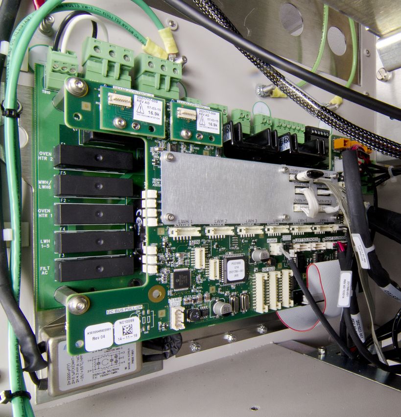
Physical Location
The PECM is mounted to the left inside wall of the EC cabinet. All fuses and electrical
connections are readily accessible.
Figure 2-10 PECM3 Mounted in EC
Maxum II Reference Manual
Manual, 7/2017, 2000596-001 27Electronic Compartment Component Descriptions and Maintenance Procedures
2.2 Power Entry and Control Module
2.2.4 Replacement Procedure
General Precautions
The PECM is the entry point for the line voltage for the entire analyzer.
Note
Specific additional instructions are provided with tags placed on the Maxum II and in the custom
application drawing package noted below. Installation must include all of the items noted in
both of these as well as the manuals. The tagging and custom application drawing package
are unique to the particular Maxum II.
● This procedure must be performed by a user who has detailed knowledge of the Maxum.
If a customer does not have the knowledge required for this procedure, then it is
recommended that Siemens Field Service personnel be contracted to assist.
● A tool kit including both standard and metric wrenches, Hex wrenches, and nut drivers is
required to perform this procedure.
● Before beginning replacement, be sure to save a current database of the application to be
reloaded after the PECM is replaced in case this becomes necessary.
WARNING
Voltage dangerous to life is present on the PECM. Failure to observe proper safety measures
can cause severe injury or death.
Before beginning to remove or install the PECM assembly, the power must be externally
removed from the GC. AC power comes directly into this board for regulation and distribution
in the electronics enclosure, so power must be removed and secured/tagged to prevent
inadvertent application while this procedure is being performed.
2.2.4.1 Troubleshooting
PECM Status LEDs
The PECM3 should start automatically once power is applied. If the unit is not operational after
applying power, then review the information below to aid in correcting the problem.
The most common issue with replacing the PECM3 is cables, wiring connections, and jumpers.
Check all of the cable connections to ensure that they are seated and connected properly.
Maxum II Reference Manual
28 Manual, 7/2017, 2000596-001Electronic Compartment Component Descriptions and Maintenance Procedures
2.2 Power Entry and Control Module
The alarm system can also provide direct information on alarms for an error. Review the alarms
to see if they provide an indication of the problem. Each alarm has a written description that
may provide an indication of the problem area.
The LEDs on the PECM board can help with LEFT Heater Status RIGHT Heater status
troubleshooting problems. There are two
sets of LEDs: one on each side of the front Heater 1 Air Pressure Heater 2 Air Pressure
board as shown in the diagram to the right. Heater 1 Power Activate Heater 2 Power Activate
The bottom set of three LEDs is the same as
PECM-CTRL PCB
Heater 1 Temp Limit Heater 2 Temp Limit
used on other boards (described below.) The Heater 1 Overtemp Heater 2 Overtemp
left set is for the PECM software. (The other
LEDs are not used for PECM1 replacement.)
The corrective action to take for each of the Normal Normal Temperature
LED indications is noted below with a correc‐PECM Status Fault Fault Controller
tive action reference number on the diagram Warning Warning
Status
at the right. The normal state indication is
shown in the diagram below.
PECM LEDs
State 1
State 5 - Warning condition; data good temporarily
1. If all units in this state, then power to the analyzer and/
or board is not active
2. Reset the device or cycle power
3. Check power connections to board (AC and 24VDC)
State 6 - Fault condition; data invalid
4. Replace unit
State 2 State 3 - Address assignment
State 4 - Normal operation
1. Reset the device or cycle analyzer power
2. Replace unit
State 1 - Power off
State 3
State 2 - Self test
1. Reset the device or cycle analyzer power
2. If all modules are in State 3, then SNECON is not
communicating (check cabling and connections)
3. Replace unit
State 4 Normal Operation
Normal
State 5
1. Reset the device or cycle power Fault
2. Check communication cable connections Warning
State 6
PECM LED Interpretation
1. Reset the device or cycle power
2. Check communication cable connections
3. Check for missing Temp Limit setpoint boards
4. Check for shorted or open RTDs
5. Replace the unit
6. Replace other connected units
Maxum II Reference Manual
Manual, 7/2017, 2000596-001 29Electronic Compartment Component Descriptions and Maintenance Procedures
2.2 Power Entry and Control Module
2.2.4.2 Removing The PECM
Precautions
Before starting this procedure, follow the steps in the General Analyzer Shutdown Procedure.
WARNING
Voltage dangerous to life exists. Failure to follow proper safety procedures may result in
severe injury or death.
Before beginning to remove or install the PECM assembly, the power must be externally
removed from the GC. AC power comes directly into this board for regulation and distribution
in the electronics enclosure, so power must be removed and secured/tagged to prevent
inadvertent application while this procedure is being performed.
WARNING
High-voltage circuitry. Failure to follow proper procedures may result in equipment damage,
personal injury or death.
The cable harness connectors and the chassis plugs associated with the Heater circuits are
marked with orange identifier tags. Before reconnecting any connector or plug to a Heater
circuit, ensure that the orange identifier tag on the connector or plug reads identical to the
orange identifier tag on its mating connector.
CAUTION
Observe proper fuse values to prevent equipment damage or personal injury.
The PECM1 is used in applications with both 115VAC and 230VAC power. Before installing
a replacement assembly, ensure that the correct fuses for the particular application are
installed in the replacement PECM3.
Procedure
1. Open electronics door. If the latch is locked, use 4mm (5/32’”) Allen wrench to unlock.
2. Label all cable connections before disconnecting if they are not already labeled. Be sure
to read the Warning below concerning those tagged with orange labels.
3. Unplug cables from all PECM connectors.
4. Unplug the atmospheric reference tube from the purge switch. (labelled “Purge SW”, tubing
connection next to the back wall of the EC, on the PECM1.
5. Use a 5mm nut driver to loosen two hex nuts at the top of each side of base plate of the
PECM.
6. Slide the PECM up and then lift the PECM off of the mounting bolts.
Maxum II Reference Manual
30 Manual, 7/2017, 2000596-001Electronic Compartment Component Descriptions and Maintenance Procedures
2.2 Power Entry and Control Module
2.2.4.3 Installing The New PECM
Procedure
1. On the replacement PECM3 assembly do the following:
– Set the Purge Disable jumper JP2 to the same setting as the PECM being replaced.
– Install the appropriate fuses for either 115VAC or 230VAC in Fuses F1 and F2 and install
fuse covers.
– Move jumper cables or termination plugs to the replacement PECM.
– Move the TL/OT modules from the old PECM to the replacement PECM, in the mounting
locations marked “TEMP CONTROL 1” and TEMP CONTROL 2”. These are required
to avoid false alarm codes.
– If Heater Termination Plugs are installed in the old PECM instead of cables at the
positions marked “TEMP RTD 1” and “TEMP RTD 2”, move these to identical locations
on the replacement PECM. The plugs disable the PECM temperature circuits, including
the LEDs.
2. Ensure that there are no wires behind the mounting position of the PECM.
3. Because the atmospheric Purge switch SW1 is near the back wall after the PECM is
installed, if desired, the Purge tube may be installed on SW1 before mounting the PECM
in the next step.
4. Install the replacement PECM on the two mounting bolts.
5. Tighten the two 5mm hex nuts.
6. Start at the back of new controller and plug in the following cables (see the connector
identification illustrations)
– If not already connected in step 12, connect the Purge switch SW1 (tubing connection)
– Relay power plug TB9 and Heater Relay Control cable
– Fan power cable plug J18, and 24VDC power cables to the orange TB1 and TB2 on top
board (there are TB1 and TB2 AC connectors on the bottom board as well - see
illustration at right.)
– I2C connections (J24 - J26, J30 - J33)
– Low wattage heater connections (TB8, TB3 to TB5, and LWH1 to LWH6)
– AC inputs (TB1, TB2, & TB10.)
– Heater pressure switch (J10) (If no cable, then a jumper is needed.)
7. When replacing in a unit that has a MMI-1, then connect the MMI LED cable to J17.
8. Connect the Purge Signal cable to J1302.
9. Move 24V cable (from power supply) from WDB J1 to PECM3 TB1.
10.Add 24V power cable, 2021837-001 from PECM3 TB2 to WDB J1.
Maxum II Reference Manual
Manual, 7/2017, 2000596-001 31Electronic Compartment Component Descriptions and Maintenance Procedures
2.3 System Controller Version 2.1 (SYSCON2.1)
11.Ensure the correct fuses are in the correct positions, as shown in PECM AC Power
Distribution illustration.
12.When the procedure is completed, follow the steps in the General Analyzer Startup
Procedure.
2.3 System Controller Version 2.1 (SYSCON2.1)
2.3.1 Description
The System Controller (SYSCON2.1) is a combination of two interconnected boards that
together function as the control processor and motherboard for the Maxum analyzer.
The SYSCON2.1 consists of two boards, the Communication and Analytical Control (CAC3)
board and the SYSCON Interface Board (SIB3). The CAC3 contains the processor and
memory functions for the SYSCON2.1 as well as control of external Ethernet communications
(via the Ethernet Switch Board). The CAC3 is mounted on and operates in conjunction with
the SIB3. With the exception of external Ethernet, the SIB3 contains all interfaces provided by
the SYSCON2.1.
The CAC3 on the SYSCON2.1 stores the analyzer application database, combines all data
results, and performs additional high-level data processing and calculations. All network
communications, maintenance panel and analyzer functions are also coordinated by the
SYSCON2.1. The SYSCON2.1 provides communication between the Controller Board, I/O
Boards and the EC operating modules.
More information about the SYSCON can be found in the System Controller version 2
(SYSCON2.1) Installation Manual (Siemens part number A5E02643617001).
Additional Functions
● Processing and communicating the ● Display and operator control
measurement values ● Controlling associated systems, such as
● Controlling system functions, such as gas supply
calibration ● Generating reports
Software Support
The SYSCON2.1 is supported only by software version 5.2 or greater.
Maxum II Reference Manual
32 Manual, 7/2017, 2000596-001Electronic Compartment Component Descriptions and Maintenance Procedures
2.3 System Controller Version 2.1 (SYSCON2.1)
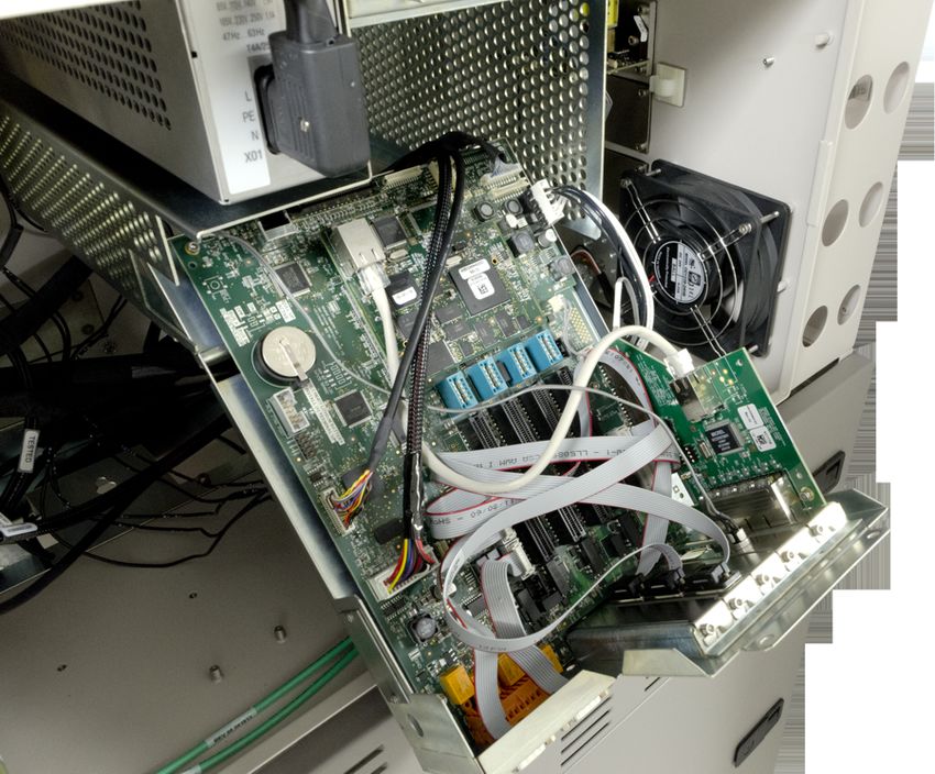
2.3.2 Mechanical
Overview
The SYSCON2.1 board pair resides in the SYSCON assembly. This assembly is a pullout,
drop-down drawer located on a slide rail assembly mounted to the upper wall of the Electronic
Enclosure. The SYSCON assembly is a card cage housing the SYSCON2.1 boards, the
Ethernet Switch Board, and any other associated hardware such as I/O boards.
Serial
SYSCON2.1 External
Ethernet
Intrinsic-Safety Ground Connection Points Ports Cage Ports
TIB Door Assembly
I/O Display Cable Routing
Connectors Into SYSCON
Figure 2-11 SYSCON2.1 In Electronics Enclosure
The Color Touchscreen cables directly to the
SIB3 through an opening in the rear of the SY‐
SCON assembly.
All PC boards in the SYSCON assembly are
visible through the front of the drawer for making
all I/O connections. Interface connectors to the
front panel display, and communication connec‐
tors are also located and labeled on the front of
the drawer.
SYSCON2.1 Drawer
Maxum II Reference Manual
Manual, 7/2017, 2000596-001 33Electronic Compartment Component Descriptions and Maintenance Procedures
2.3 System Controller Version 2.1 (SYSCON2.1)
2.3.3 SYSCON2.1 Components
2.3.3.1 Communication and Control Board (CAC3)
The Communication and Control board (CAC) is a standardized, single-board central
processing unit for intended for use in Siemens products. For the Maxum family of products
the third generation of the CAC board (CAC3) is used.
The CAC3 includes an on-board 10/100 Ethernet controller, used for connection to external
Ethernet. This is connected via a short RJ-45 patch cable to the Ethernet Switch Board, which
resides in a card slot on the SIB3.
More information and details pertaining to the CAC3 can be found in the System Controller
version 2.1 (SYSCON2.1) Installation Manual (Siemens part number A5E02643617001).
Figure 2-12 CAC3 Board (Part Number A5E02599492004)
Maxum II Reference Manual
34 Manual, 7/2017, 2000596-001You can also read