Switchgear Type 8DJH for Secondary Distribution Systems up to 24 kV, Gas-Insulated - Medium-Voltage Switchgear
←
→
Page content transcription
If your browser does not render page correctly, please read the page content below
Catalog
               Switchgear Type 8DJH for Secondary
HA 40.2 ·
Edition 2017   Distribution Systems up to 24 kV,
               Gas-Insulated
               Medium-Voltage Switchgear

                                             siemens.com/8DJH
Application
     Typical uses
    R-HA40-111.tif

                                                                                                                                    R-HA40-112.tif
                                                                                  Application
                                                                                  in public
                                                                                  and industrial
                                                                                  energy systems
    R_HA40-150a tif

                                                                                                                                    R_HA40_160 tif
                                                                                                                                    R-HA40-157 tif
    R-HA40-110.tif

2                     Switchgear Type 8DJH for Secondary Distribution Systems up to 24 kV, Gas-Insulated · Siemens HA 40.2 · 2017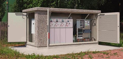
Contents

Switchgear Type 8DJH                                                        Application                                                 Page
for Secondary                                                               Types, typical uses, ratings, approvals                     4 and 5

                                                                            Requirements
Distribution Systems                                                        Features, safety, technology, classification                 6 to 8

up to 24 kV,                                                                Technical Data
                                                                            Electrical data of the switchgear                           9
Gas-Insulated                                                               Switching capacity and
                                                                            classification of switching devices                          10 and 11

Medium-Voltage Switchgear                                                   Product Range
                                                                            Individual panels and modules                               12 to 14
Catalog HA 40.2 · 2017                                                      Air-insulated billing metering panels                       15
                                                                            Product range overview of panel blocks                      16 and 17
Invalid: Catalog HA 40.2 · 2014
                                                                            Design
                                                                            Panel design                                                18 to 21
siemens.com / medium-voltage-switchgear
                                                                            Outdoor enclosure                                           22
siemens.com/ 8DJH
                                                                            Operation                                                   23

                                                                            Components
                                                                            Three-position switch-disconnector                          24 to 26
                                                                            Vacuum circuit-breaker                                      27 to 29
                                                                            Busbar extension, modularity                                30
                                                                            HV HRC fuse assembly                                        31
                                                                            Allocation of HV HRC fuses
                                                                            and transformer ratings                                     32 to 36
                                                                            Current and voltage transformers                            37 to 41
                                                                            Current and voltage sensors                                 42 and 43
                                                                            Cable connections, cable plugs                              44 to 50
                                                                            Interlocks, locking devices                                 51
                                                                            Indicating and measuring equipment                          52 to 60
                                                                            Transformer monitor system,
                                                                            time-fuse-link protection system                            61
                                                                            Intelligent transformer substation                          62 and 63
                                                                            Protection systems                                          64
                                                                            Low-voltage compartment, low-voltage niche                  65

                                                                            Dimensions
                                                                            Room planning, switchgear installation                      66 to 68
                                                                            Individual panels and modules,
                                                                            panel combinations                                          69 to 81
                                                                            Outdoor enclosure                                           82
                                                                            Floor openings and fixing points                             83 to 86

                                                                            Installation
          The products and systems described in this catalog                Shipping data, transport                                    87 and 88
          are manufactured and sold according to a certified
          management system (acc. to ISO 9001, ISO 14001
                                                                            Standards
          and BS OHSAS 18001).
                                                                            Standards, specifications, guidelines                        89 to 91

                                  Switchgear Type 8DJH for Secondary Distribution Systems up to 24 kV, Gas-Insulated · Siemens HA 40.2 · 2017    3
Application
    Types

                                                                                                   R-HA40-150a.eps
                                 R-HA40-149b tif

                                                                                                                                              R-HA40-156.eps

    Individual circuit-breaker                     RRT block                                                         8DJH Compact RRT block
    panel 500 mm

4    Switchgear Type 8DJH for Secondary Distribution Systems up to 24 kV, Gas-Insulated · Siemens HA 40.2 · 2017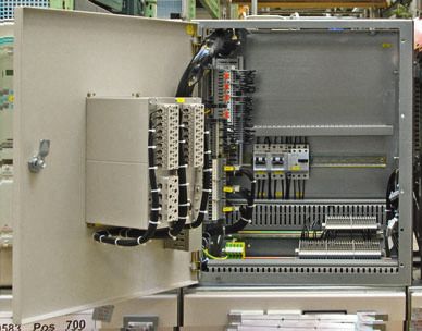
Application
                                                                                                      Typical uses, ratings, approvals

8DJH switchgear is a factory-assembled, type-tested,                Electrical data (maximum values) and dimensions
3-pole metal-enclosed single-busbar switchgear for indoor            Rated voltage              kV    7.2     12         15      17.5   24
installation.                                                        Rated frequency            Hz    50 / 60 50 / 60 50 / 60 50 / 60 50 / 60
8DJH switchgear is used in public and industrial energy              Rated short-duration       kV    20 1)   28 2)      36      38     50
systems of the secondary distribution level, e.g. in                 power-frequency
                                                                     withstand voltage
• Local ring-main units, customer transfer substations and           Rated lightning impulse    kV    60 1)   75 2)      95      95     125
  switching substations of power supply and public utilities         withstand voltage
• Wind power and solar plants, hydroelectric power plants            Rated peak                 kA    63 / 65 63 / 65 63 / 65 63 / 65 50 / 55
• Water and sewage treatment plants                                  withstand current
                                                                     Rated short-circuit        kA    63 / 65 63 / 65 63 / 65 63 / 65 50 / 55
• Airports, railway stations, underground railway stations
                                                                     making current
• Open-cast mining facilities
                                                                     Rated short-time           kA    20 / 21 20 / 21 20 / 21 20 / 21 20 / 21
• High-rise buildings.                                               withstand current 3 s
                                                                     Rated short-time           kA    25      25         25      25     20 / 21
                                                                     withstand current 1 s
                                                                     Rated normal current       A     630     630        630     630    630
                                                                     of the busbar
                                                                     Rated normal current       A     200 / 250 / 400 / 630 3)
                                                                     of feeders
                                                                     Width (feeders)            mm    310 / 430 / 500   3)

                                                                     Depth
                                                                     – without pressure
                                                                       relief duct              mm    775     775        775     775    775
                                                                     – with pressure
                                                                       relief duct              mm    890     890        890     890    890
                                                                     Height
                                                                     without low-voltage
                                                                     compartment and
                                                                     pressure relief duct       mm    optionally 1040 / 1200 / 1400 / 1700

                                                                    1) 32 kV / 60 kV according to some national requirements
                                                                    2) 42 kV / 75 kV according to some national requirements
                                                                    3) Depending on the feeder function and the selected design options
National approval GOST
By certification in the system GOST R in Russia, 8DJH
is approved for application at the voltage levels 6 kV,
10 kV and 20 kV.
The approval is valid in the countries Russia, Belarus,
Kazakhstan and Ukraine.

                             Switchgear Type 8DJH for Secondary Distribution Systems up to 24 kV, Gas-Insulated · Siemens HA 40.2 · 2017          5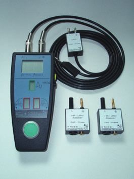
Requirements
    Features                                                               Safety

    Environmental independence                                             Personal safety
    Hermetically tight, welded switchgear vessels made of                  • Safe-to-touch and hermetically sealed primary enclosure
    stainless steel as well as single-pole solid insulation make           • Standard degree of protection IP 65 for all high-voltage
    the parts of the primary circuit under high voltage of 8DJH              parts of the primary circuit, at least IP 2X for the switch-
    switchgear                                                               gear enclosure according to IEC 60529 and VDE 0470-1
    • Insensitive to certain aggressive ambient conditions,                • Cable terminations, busbars and voltage transformers
      such as:                                                               are surrounded by earthed layers. All high-voltage parts
    – Saline air                                                             including the cable terminations, busbars and voltage
    – Air humidity                                                           transformers are metal-enclosed
    – Dust
                                                                           • Operating mechanisms and auxiliary switches safely
    – Condensation
                                                                             accessible outside the primary enclosure (switchgear
    • Tight to ingress of foreign objects, such as:
    – Dust                                                                   vessel)
    – Pollution                                                            • High resistance to internal arcs by logical mechanical
    – Small animals                                                          interlocks and tested switchgear enclosure
    – Humidity.                                                            • Panels tested for resistance to internal faults up to 21 kA
                                                                           • Capacitive voltage detecting system to verify safe
    Compact design                                                           isolation from supply
    Thanks to the use of SF6 insulation, compact dimensions
                                                                           • Due to the system design, operation is only possible
    are possible. Thus:
                                                                             with closed switchgear enclosure
    • Existing switchgear rooms and substation rooms
      can be used effectively                                              • Logical mechanical interlocks prevent maloperation
    • New constructions cost little                                        • HV HRC fuses and cable sealing ends are only accessible
                                                                             when outgoing feeders are earthed
    • Costly city-area space is saved.
                                                                           • Feeder earthing via make-proof earthing switches.
    Maintenance-free design
    Switchgear vessels designed as sealed pressure systems,                Security of operation
    maintenance-free switching devices and enclosed cable                  • Hermetically sealed primary enclosure independent of
    plugs ensure:                                                            environmental effects (pollution, humidity and small
    • Maximum supply reliability                                             animals)
    • Personnel safety                                                     • Welded switchgear vessels, sealed for life
    • Sealed-for-life design according to IEC 62271-200                    • Maintenance-free in an indoor environment
      (sealed pressure system)                                               (IEC 62271-1 and VDE 0671-1)
    • Installation, operation, extension and replacement                   • Operating mechanisms of switching devices accessible
      without SF6 gas work                                                   outside the primary enclosure (switchgear vessel)
    • Reduced operating costs                                              • Metal-coated, plug-in inductive voltage transformers
    • Cost-efficient investment                                               mounted outside the SF6 switchgear vessel
    • No maintenance cycles.                                               • Current transformers as ring-core current transformers
                                                                             mounted outside the SF6 switchgear vessel
    Innovation                                                             • Complete switchgear interlocking system with logical
    The use of digital secondary systems and combined protec-                mechanical interlocks
    tion and control devices ensures:
                                                                           • Mechanical position indicators integrated in the mimic
    • Clear integration in process control systems                           diagram
    • Flexible and highly simplified adaptation to new system               • Minimum fire load
       conditions and thus cost-efficient operation.
                                                                           • Option: Resistance against earthquakes.
    Service life
                                                                           Reliability
    Under normal operating conditions, the expected service life
    of gas-insulated switchgear 8DJH is at least 35 years, probably        • Type and routine-tested
    40 to 50 years, taking the tightness of the hermetically weld-         • Standardized and manufactured using numerically
    ed switchgear vessel into account. The service life is limited by        controlled machines
    the maximum number of operating cycles of the switchgear               • Quality assurance in accordance with DIN EN ISO 9001
    devices installed:                                                     • More than 500,000 switchgear panels of Siemens in
    • For circuit-breakers, according to the endurance class                 operation worldwide for many years.
      defined in IEC 62271-100
    • For three-position disconnectors and earthing switches,
      according to the endurance class defined in IEC 62271-102
    • For three-position switch-disconnectors and earthing
      switches, according to the endurance class defined in
      IEC 62271-103.

6    Switchgear Type 8DJH for Secondary Distribution Systems up to 24 kV, Gas-Insulated · Siemens HA 40.2 · 2017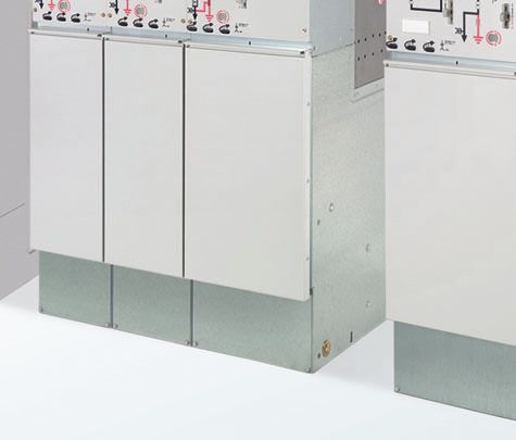
Requirements
                                                                                                                               Technology

General                                                                Modular design
• Three-pole primary enclosure, metal-enclosed                         • Individual panels and panel blocks can be lined up and
• Welded switchgear vessel without seals, made of stain-                 extended at will – without gas work on site
  less steel, with welded-in bushings for electrical connec-           • Low-voltage compartment available in 4 overall heights,
  tions and mechanical components                                        wiring to the panel via plug connectors.
• Insulating gas SF6 (fluorinated greenhouse gas)
• Maintenance-free components under normal ambient                     Panel design
  conditions according to IEC 62271-1 and VDE 0671-1                   • Factory-assembled, type-tested
• Three-position switch-disconnector with load-break                   • Metal-enclosed, with metallic partitions 1)
  function and make-proof earthing function                            • Hermetically tight, welded switchgear vessel made of
• Vacuum circuit-breaker                                                 stainless steel
• Cable connection with outside-cone plug-in system                    • Maintenance-free
– In ring-main and circuit-breaker feeders with bolted                 • Degree of protection
  contact (M16)                                                        – IP 65 for all high-voltage parts of the primary circuit in
– In transformer feeders with plug-in contact or optionally              the gas-insulated panels
  with bolted contact (M16)                                            – IP 2X for the switchgear enclosure
• Wall-standing or free-standing arrangement                           • Vacuum circuit-breaker with three-position disconnector
                                                                         for disconnecting and earthing
• Pressure relief downwards, optionally to the rear or
  upwards via pressure absorber systems.                               • Three-position switch-disconnector
                                                                       • Cable connection with outside-cone plug-in system
Interlocks                                                               according to DIN EN 50181
• According to IEC 62271-200 and VDE 0671-200                          • Wall-standing arrangement, optionally free-standing
• Logical mechanical interlocks prevent maloperation                     arrangement
• Logical mechanical interlocks and the constructive                   • Installation and possible later extension of existing
  features of the three-position switches prevent mal-                   panels without gas work
  operation as well as access to the cable connection of               • Replacement of instrument transformers without gas
  the feeders and HV HRC fuses under voltage                             work, as they are located outside the gas compartments
• Impermissible and undesired operations can be prevent-               • Enclosure made of sendzimir-galvanized sheet steel,
  ed by means of locking devices provided at the switching               front cover powder-coated in color “light basic” (SN 700)
  devices                                                              • Low-voltage compartment removable, plug-in bus wires
• A detailed description of all interlocking options is                • Lateral, metallic wiring ducts for control cables.
  available on page 51.
                                                                       Instrument transformers
Insulating system                                                      • Current transformers not subjected to dielectric stress
• Switchgear vessel filled with SF6 gas                                 • Easy replacement of current transformers designed as
• Features of SF6 gas:                                                   ring-core transformers
– Non-toxic                                                            • Metal-coated, plug-in voltage transformers.
– Odorless and colorless
– Non-inflammable                                                       Vacuum circuit-breaker
– Chemically neutral                                                   • Maintenance-free under normal ambient conditions
– Heavier than air                                                       according to IEC 62271-1 and VDE 0671-1
– Electronegative (high-quality insulator)                             • No relubrication or readjustment
– Global Warming Potential GWP = 22,800                                • Up to 10,000 operating cycles
• Pressure of SF6 gas in the switchgear vessel                         • Vacuum-tight for life.
  (absolute values at 20 °C):
– Rated filling level: 150 kPa                                          Secondary systems
– Design pressure: 180 kPa                                             • Customary protection, measuring and control equipment
– Design temperature of the SF6 gas: 80 °C                             • Option: Numerical multifunction protection relay with
– Operating pressure of bursting disc: ≥ 300 kPa                         integrated protection, control, communication, operat-
– Bursting pressure: ≥ 550 kPa                                           ing and monitoring functions
– Gas leakage rate: < 0.1 % per year.                                  • Can be integrated in process control systems.

1) Corresponds to “metal-clad” according to
   former standard IEC 60298

                                Switchgear Type 8DJH for Secondary Distribution Systems up to 24 kV, Gas-Insulated · Siemens HA 40.2 · 2017   7
Requirements
    Classification

    8DJH switchgear is classified according to
    IEC / EN 62271-200 / VDE 0671-200.

    Design and construction                                                   Internal arc classification (Option)
    Partition class                          PM (partition of metal)           Designation of the internal arc      Rated voltage 7.2 kV to 24 kV
    Loss of service continuity category                                        classification IAC
    for panels or panel blocks                                                 IAC class for 8DJH Standard and
      – With HV HRC fuses (T, H)             LSC 2                             8DJH Compact design for
      – Without HV HRC fuses (R, L, ...)     LSC 2                               – Wall-standing arrangement        IAC A FL
    Billing metering panel M                 LSC 1                               – Free-standing arrangement        IAC A FLR
    Cable panel K                                                              Additionally only for
    Accessibility to compartments                                              8DJH Compact design for
    (enclosure)                                                                  – Installation in substations      IAC A F
      – Busbar compartment                   – Non-accessible                      without control aisle 1)
      – Switching-device compartment         – Non-accessible                  Type of accessibility A              Switchgear in closed electrical
      – Low-voltage compartment              – Tool-based                                                           service location, access
        (option)                                                                                                    “for authorized personnel only”
      – Cable compartment for panels                                                                                (according to IEC / EN 62271-200)
        or panel blocks                                                          –F                                 Front
        – With HV HRC fuses (T)              – Interlock-controlled              –L                                 Lateral
        – Without HV HRC fuses (R, L, ...)   – Interlock-controlled              –R                                 Rear
        – Only cable feeder (K)              – Tool-based                                                           (for free-standing arrangement)
        – Metering panels                    – Tool-based                      Arc test current                     Up to 21 kA
          (air-insulated) (M)                                                  Test duration                        1s

    1) Rear space required for pressure relief.
       Application recommended in prefabricated substations without control aisle, tested according to IEC 62271-202.

8    Switchgear Type 8DJH for Secondary Distribution Systems up to 24 kV, Gas-Insulated · Siemens HA 40.2 · 2017
Technical Data
                                                                                                                  Electrical data of the switchgear

Rated insulation level                   Rated voltage Ur                                          kV 7.2         12        15    17.5    24
                                         Rated short-duration power-frequency
                                         withstand voltage Ud
                                         – Phase-to-phase, phase-to-earth, open contact gap        kV 20          28 / 42 1) 36   38      50
                                         – Across the isolating distance                           kV 23          32 / 48 1) 39   45      60
                                         Rated lightning impulse withstand voltage Up
                                         – Phase-to-phase, phase-to-earth, open contact gap        kV 60          75        95    95      125
                                         – Across the isolating distance                           kV 70          85        110   110     145
Rated frequency fr                                                                                 Hz 50 / 60
Rated normal current Ir 2)               for ring-main feeders                                      A 400 or 630
                                         for busbar                                                 A 630
                                         for circuit-breaker feeders                                A 250 or 630
                                         for transformer feeders                                    A 200 3)
50 Hz Rated short-time                   for switchgear with t k = 1 s                        up to kA 25         25        25    25      20/21 1)
      withstand current Ik               for switchgear with t k = 3 s (design option)        up to kA 20/21 1)
       Rated peak withstand current Ip                                                        up to kA 63         63        63    63      50/52.5 1)
       Rated short-circuit               for ring-main feeders                                up to kA 63         63        63    63      50/52.5 1)
       making current Ima                for circuit-breaker feeders                          up to kA 63         63        63    63      50/52.5 1)
                                         for transformer feeders                              up to kA 63         63        63    63      50/52.5 1)
60 Hz Rated short-time                   for switchgear with t k = 1 s                        up to kA 25         25        25    25      20/21 1)
      withstand current Ik               or switchgear with t k = 3 s (design option)         up to kA 20/21 1)
       Rated peak withstand current Ip                                                        up to kA 65         65        65    65      52/55 1)
       Rated short-circuit               for ring-main feeders                                up to kA 65         65        65    65      52/55 1)
       making current Ima                for circuit-breaker feeders                          up to kA 65         65        65    65      52/55 1)
                                         for transformer feeders                                   kA 65          65        65    65      52/55 1)
Filling pressure                         Rated filling level pre (absolute)                        kPa 150
(pressure values at 20 °C)               Minimum functional level pme (absolute)                  kPa 130
Ambient air temperature T 4)             Operation                             standard             °C –25 to +55
                                                                               on request           °C –40 to +70
                                         Storage / transport                   standard             °C –25 to +55
                                                                               on request           °C –40 to +70
Degree of protection                     for gas-filled switchgear vessel                               IP65
                                         for switchgear enclosure                                      IP2X / IP3X 1)
                                         for low-voltage compartment                                   IP3X / IP4X 1)

1) Design option
2) The rated normal currents apply to ambient air temperatures of max. 40 °C.
   The 24-hour mean value is max. 35 °C (according to IEC / EN 62271-1 / VDE 0671-1)
3) Depending on HV HRC fuse-link
4) Minimum and maximum permissible ambient air temperature depending on the secondary equipment used

                                  Switchgear Type 8DJH for Secondary Distribution Systems up to 24 kV, Gas-Insulated · Siemens HA 40.2 · 2017          9
Technical Data
     Switching capacity and classification of switching devices

     Three-position switch-disconnector
     Switching capacity for general-purpose switches according to IEC / EN 62271-103 (former: IEC / EN 60265-1 / VDE 0670-301)
                        Rated voltage Ur                                                                     kV 7.2       12       15       17.5     24
     Test duty          Rated mainly active load                        100 operations Iload [I1]             A 630
     TDload             breaking current Iload                          20 operations 0.05 Iload [I1]         A 31.5
     Test duty          Rated closed-loop breaking current Iloop [I2a]                                        A 630
     TDloop
     Test duty          Rated cable-charging breaking current Icc [I4a]                                       A 68
     TDcc
     Test duty          Rated line-charging breaking current Ilc [I4b]                                        A 68
      TDlc
     Test duty          Rated short-circuit making current Ima          50 Hz                           up to kA 63       63       63       63       50/52.5 1)
      TDma                                                              60 Hz                           up to kA 65       65       65       65       52/55 1)
     Test duty          Rated earth-fault breaking current Ief1 [I6a]                                         A 200
      TDef1
     Test duty          Rated cable-charging breaking current and line-charging breaking
      TDef2             current under earth-fault conditionsIef2 [I6b (√3 · I4a) or I6b (√3 · I4b)]           A 115
     Number of operating cycles, mechanical / Classification                                                   n 1000/M1
     Number of operating cycles, electrical with Iload / Classification                                        n 100/E3
     Number of short-circuit making operations with Ima / Classification                                       n 5 / E3    5 / E3   5 / E3   5 / E3   5 / E3
     C-classification for general-purpose switches (no restrikes, TD: Icc, Ilc)                                  C2        C2       C2       C2       C2

     Switching capacity for make-proof earthing switch according to IEC / EN 62271-102 / VDE 0671-102
     Rated short-circuit making current Ima                             50 Hz                           up to kA 63       63       63       63       50/52.5 1)
                                                                        60 Hz                           up to kA 65       65       65       65       52/55 1)
     Number of operating cycles, mechanical / Classification                                                   n 1000/M0
     Number of short-circuit making operations                                                                n 5
     Classification                                                                                              E2

     Switch-disconnector / fuse combination
     Switching capacity for switch-disconnector / fuse combination according to IEC / EN 62271-105 / VDE 0671-105
     Rated normal current                                                                                     A 200 2)
     Rated transfer current Itransfer                                                                         A 1500      1500     1300     1300     1300

     Switching capacity for make-proof earthing switch, feeder side, in transformer feeder with HV HRC fuses
     Rated short-circuit making current Ima                             50 Hz                                kA 6.3
                                                                        60 Hz                                kA 6.5
     Rated short-time withstand current Ik with t k = 1 s                                                    kA 2.5

     1) Design option
     2) Depending on HV HRC fuse-link

10    Switchgear Type 8DJH for Secondary Distribution Systems up to 24 kV, Gas-Insulated · Siemens HA 40.2 · 2017
Technical Data
Switching capacity and classification of switching devices
Vacuum circuit-breaker
Switching capacity according to IEC / EN 62271-100 / VDE 0671-100
Type 1.1 with three-position disconnector
Rated voltage Ur kV 7.2 12 15 17.5 24
Rated normal current of feeders Ir A 630
50 Hz Rated short-time for switchgear with t k = 1 s up to kA 25 25 25 25 20/21 1)
withstand current Ik for switchgear with t k = 3 s up to kA 20/21 1)
Rated peak withstand current Ip up to kA 63 63 63 63 50/52.5 1)
Rated short-circuit breaking current Isc up to kA 25 25 25 25 20/21 1)
Rated short-circuit making current Ima up to kA 63 63 63 63 50/52.5 1)
60 Hz Rated short-time for switchgear with t k = 1 s up to kA 25 25 25 25 20/21 1)
withstand current Ik for switchgear with t k = 3 s up to kA 20/21 1)
Rated peak withstand current Ip up to kA 65 65 65 65 52/55 1)
Rated short-circuit breaking current Isc up to kA 25 25 25 25 20/21 1)
Rated short-circuit making current Ima up to kA 65 65 65 65 52/55 1)
Number of mechanical operating cycles for disconnector n 1000
Number of mechanical operating cycles for earthing switch n 1000
Number of mechanical operating cycles for circuit-breaker n 10,000
Classification of circuit-breaker M2, E2, C2, S2
Classification of disconnector M0
Classification of make-proof earthing switch E2
Rated operating sequence O – 0.3 s – CO – 3 min – CO
O – 0.3 s – CO – 15 s – CO on request
Number of short-circuit breaking operations n 25 or 50
Type 2 with three-position disconnector
Rated voltage Ur kV 7.2 12 15 17.5 24
Rated normal current of feeders Ir A 250 A or 630 A
50 Hz Rated short-time for switchgear with t k = 1 s up to kA 25 25 25 25 20/21 1)
withstand current Ik for switchgear with t k = 3 s up to kA 20/21 1)
Rated peak withstand current Ip up to kA 63 63 63 63 50/52.5 1)
Rated short-circuit breaking current Isc up to kA 25 25 25 25 20/21 1)
Rated short-circuit making current Ima up to kA 63 63 63 63 50/52.5 1)
60 Hz Rated short-time for switchgear with t k = 1 s up to kA 25 25 25 25 20/21 1)
withstand current Ik for switchgear with t k = 3 s up to kA 20/21 1)
Rated peak withstand current Ip up to kA 65 65 65 65 52/55 1)
Rated short-circuit breaking current Isc up to kA 25 25 25 25 20/21 1)
Rated short-circuit making current Ima up to kA 65 65 65 65 52/55 1)
Number of mechanical operating cycles for disconnector n 1000
Number of mechanical operating cycles for earthing switch n 1000
Number of mechanical operating cycles for circuit-breaker n 2000
Classification of circuit-breaker M1, E2, C1, S1
Classification of disconnector M0
Classification of make-proof earthing switch E2
Rated operating sequence O – 3 min – CO – 3 min – CO
Number of short-circuit breaking operations n 6 or 20
1) Design option
Switchgear Type 8DJH for Secondary Distribution Systems up to 24 kV, Gas-Insulated · Siemens HA 40.2 · 2017 11Product Range
Individual panels and modules – freely configurable for up to 4 functions in the block
Cable feeder Cable feeder
Type K2) Type K(E) 2)
HA40-2291 eps
HA40-2125a eps
310 mm wide 430 mm wide
1) 1)
Vacuum
with make-proof
circuit-breaker
earthing switch
Three-position
switch-disconnector
Three-position
disconnector
Capacitive voltage
detecting system
HV HRC fuse
Ring-main feeder Circuit-breaker feeder
Type R Type L
HA40-2124a eps
HA40-2127a eps
310 mm wide 430 mm wide Cable-type current
1) 1)
transformer
Cable connection
with outside cone
(not included in the
scope of supply)
Surge arrester
or limiter
Make-proof
earthing switch
Transformer feeder
Type T
HA40-2126a eps
430 mm wide
1)
1) Only for end
panel, on the free
connection side of
the busbar
2) Only as individual
panel and in
2-panel blocks
12 Switchgear Type 8DJH for Secondary Distribution Systems up to 24 kV, Gas-Insulated · Siemens HA 40.2 · 2017Product Range
Individual panels
Bus sectionalizer panel
with switch-disconnector with switch-fuse combination
Vacuum
Type S 1) Type H 1)
HA40-2128 eps
HA40-2129a eps
circuit-breaker
430 mm wide 430 mm wide
Three-position
switch-disconnector
Three-position
disconnector
Capacitive voltage
detecting system
Bus sectionalizer panel with switch-disconnector
Type S(620) Type S(500)
HA40-2130 eps
HA40-2131c eps
(earthing on the left) with current
620 mm wide transformer HV HRC fuse
500 mm wide
4MT3
Current transformer
Plug-in voltage
transformer 4MT3
Bus sectionalizer panel with circuit-breaker
Type V (with circuit- Design option with
HA40-2132 eps
HA40-2133b eps
breaker 1.1 or 2) current transformer
500 mm wide
4MT3 4MT3
1) Also executable as right-hand panel in panel blocks
Switchgear Type 8DJH for Secondary Distribution Systems up to 24 kV, Gas-Insulated · Siemens HA 40.2 · 2017 13Product Range
Individual panels
Ring-main feeder Circuit-breaker feeder
HA40-2134c eps
HA40-2135b eps
Type R(500) Type L(500) Vacuum
500 mm wide with circuit- circuit-breaker
1) 1)
breaker
type 1.1 or
4MT3 4MT3
type 2)
500 mm wide
Three-position
switch-disconnector
*) *)
4MC63 ... 4MC63 ...
Three-position
disconnector
Capacitive voltage
detecting system
4MT8 4MT8
*)
Three-phase
current transformer
Busbar voltage metering panel Busbar voltage metering panel,
fused on the primary side Cable-type current
Type M(500) Type M(430) transformer
HA40-2274b eps
HA40-2137c eps
500 mm wide 430 mm wide
1) 1)
Cable connection
with outside cone
(not included in the
scope of supply)
Surge arrester
or limiter
4MT3 4MT3
Plug-in voltage
transformer
Busbar earthing panel Busbar earthing panel
Type E
HA40-2138a eps
HA40-2136a eps
Type E(500)
310 mm wide 500 mm wide
1) 1)
4MT3
1) Only for end
panel, on the
free connection
side of the busbar
14 Switchgear Type 8DJH for Secondary Distribution Systems up to 24 kV, Gas-Insulated · Siemens HA 40.2 · 2017Product Range
Air-insulated billing metering panels type M, 840 mm wide
Billing metering panels with cable connection on the left
Current transformer,
cast-resin insulated
HA40-2139a eps
Voltage transformer,
P1 P2 cast-resin insulated
P1 P2
P2 P1
P2 P1
Capacitive voltage
detecting system
Fixed earthing
points for
busbar earthing
Billing metering panels with cable connection on the right P1 and P2
are terminal
HA40-2140a eps
designations of
the current
transformer
P1 P2
P1 P2
P2 P1
P2 P1
Billing metering panels with busbar connection on both sides
HA40-2141a eps
P1 P2 P2 P1 P1 P2 P2 P1
Billing metering panels with cable connection on both sides
P1 P2
P1 P2
P2 P1
P2 P1
HA40-2142a eps
Switchgear Type 8DJH for Secondary Distribution Systems up to 24 kV, Gas-Insulated · Siemens HA 40.2 · 2017 15Product Range
Product range overview of panel blocks (excerpt)
Panel block Installation dimensions Panel block Installation dimensions
Components shown in dotted lines Width Depth Height Components shown in dotted lines Width Depth Height
can be used optionally. can be used optionally.
mm mm mm mm mm mm
Panel blocks with transformer feeders, Panel blocks with circuit-breaker feeders,
optionally with busbar extension optionally with busbar extension
KT 1 transformer feeder, KL 1 circuit-breaker feeder,
K Radial cable 1 radial cable connection K Radial cable 1 radial cable connection
HA40-2108b eps
HA40-2113a eps
connection as connection as
incoming 740 775 1200 incoming 740 775 1200
feeder 1400 feeder 1400
1700 1700
K(E)T 1 transformer feeder, K(E)L 1 circuit-breaker feeder,
K Radial cable 1 radial cable connection K Radial cable 1 radial cable connection
connection as with make-proof earthing connection as with make-proof earthing
incoming switch incoming switch
feeder 860 775 1200 feeder 860 775 1200
HA40-2218a eps
HA40-2219a eps
1400 1400
1700 1700
RT 1 ring-main feeder, RL 1 ring-main feeder,
1 transformer feeder 1 circuit-breaker feeder
HA40-2109b eps
HA40-2114a eps
740 775 1040 740 775 1200
1200 1400
1400 1700
1700
RRT 2 ring-main feeders, RRL 2 ring-main feeders,
1 transformer feeder 1 circuit-breaker feeder
HA40-2115a eps
HA40-2110b eps
1050 775 1040 1050 775 1200
1200 1400
1400 1700
1700
RRRT 3 ring-main feeders, RRRL 3 ring-main feeders,
1 transformer feeder 1 circuit-breaker feeder
HA40-2111b eps
HA40-2116a eps
1360 775 1200 1360 775 1200
1400 1400
1700 1700
TRRT 2 ring-main feeders, LRRL 2 ring-main feeders,
2 transformer feeders 2 circuit-breaker feeders
HA40-2112b eps
HA40-2117a eps
1480 775 1200 1480 775 1200
1400 1400
1700 1700
16 Switchgear Type 8DJH for Secondary Distribution Systems up to 24 kV, Gas-Insulated · Siemens HA 40.2 · 2017Product Range
Product range overview of panel blocks (excerpt)
Panel block Installation dimensions Panel block Installation dimensions
Components shown in dotted lines Width Depth Height Components shown in dotted lines Width Depth Height
can be used optionally. can be used optionally.
mm mm mm mm mm mm
Panel blocks with ring-main feeders, Panel blocks with transformer feeders,
optionally with busbar extension optionally with busbar extension
RR 2 ring-main feeders TT 2 transformer feeders
HA40-2121b eps
HA40-2118a eps
620 775 1040 860 775 1200
1200 1400
1400 1700
1700
RRR 3 ring-main feeders TTT 3 transformer feeders
HA40-2122b eps
HA40-2119a eps
930 775 1040 1290 775 1200
1200 1400
1400 1700
1700
RRRR 4 ring-main feeders
HA40-2120a eps
1240 775 1200
1400
1700
Panel block Installation dimensions
Components shown in dotted lines Width Depth Height
can be used optionally.
mm mm mm
Panel blocks with transformer feeders as 8DJH Compact, without busbar extension
RRT
HA40-2360a eps
620 775 1400
1700
700 775 1400
1700
RRT-R
HA40-2361a eps
930 775 1400
1700
1010 775 1400
1700
RRT-RRT
HA40-2362a eps
1240 775 1400
1700
1400 775 1400
1700
Switchgear Type 8DJH for Secondary Distribution Systems up to 24 kV, Gas-Insulated · Siemens HA 40.2 · 2017 17Design
Panel design (examples)
Ring-main feeder Transformer feeder
Type R Section Type T Section
5 5
HA40-2144e eps
HA40-2143c eps
2 2
6 6
1 1
7 7
3 3
8 9
4 4
11
9
12
13
10
10
Circuit-breaker feeder
Type L Section
5 1 Control board (for details, see page 23)
HA40-2145e eps
2 2 Busbar arrangement
6 3 Three-position switch-disconnector
1 1 4 Pressure relief device
15 5 Wiring duct, removable, for protection
14 and / or bus wires
8 6 Switchgear vessel, filled with gas
4 7 Operating mechanism of switching device
9 8 Bushing for cable plug with bolted contact
(M16)
9 Cable compartment cover
10 Earthing busbar with earthing connection
(design option)
11 Partition
12 HV HRC fuse assembly
13 Bushing for cable plug with plug-in contact,
optionally bolted contact (M16)
10 14 Vacuum circuit-breaker
15 Circuit-breaker operating mechanism,
Type 1.1 Type 2 operating mechanism for three-position
disconnector
18 Switchgear Type 8DJH for Secondary Distribution Systems up to 24 kV, Gas-Insulated · Siemens HA 40.2 · 2017Design
Panel design (examples)
Circuit-breaker feeder
Type L(500) Section
1 Control board (for details, see page 23)
HA40-2146d eps
2 Option: Low-voltage compartment
3 Busbar arrangement
4 Vacuum circuit-breaker
2
5 Pressure relief device
6 Wiring duct, removable, for protection and / or bus wires
6 7 Switchgear vessel, filled with gas
3
8 Operating mechanism of switching device
7 9 Bushing for cable plug with bolted contact (M16)
10 Cable compartment cover
1
8 11 Option: Three-phase current transformer (protection trans-
former)
4 12 Earthing busbar with earthing connection (design option)
9
5 10
11
12
Type 2 Section
13 Low-voltage compartment (standard)
HA40-2263c eps
13 for vacuum circuit-breaker
14 Option: SIPROTEC bay controller
14
15 Option: Plug-in voltage transformer type 4MT3 on the busbar
15 16 Bushing for connection of plug-in voltage transformers
17 Option: Plug-in voltage transformer 4MT8 at the connection
16 18 Cable-type current transformer
6
3
7
1
8
4
9
5 10
11
17
18
12
Type 1.1
Switchgear Type 8DJH for Secondary Distribution Systems up to 24 kV, Gas-Insulated · Siemens HA 40.2 · 2017 19Design
Panel design (examples)
Billing metering panel
Type M, air-insulated Section
2 7
HA40-2148f eps
3
8
4
9a
1 9b
10
5
6
12
Connection: busbar – busbar
Section
7 1 Sockets for voltage detecting system
HA40-2149e eps
2 Busbar connection
3 Busbar vessel, filled with gas
6 4 Pressure relief device
8
5 Current transformer type 4MA7
1
6 Voltage transformer type 4MR
7 Wiring duct, removable, for protection and /
10
or bus wires
5 8 Niche for customer-side low-voltage equip-
ment, screwed cover
9 Bushings for connection of transformer bars,
connected with busbar extension on the right
9a and on the left 9b
10 Transformer compartment cover
11 11 Cable connection
12 Earthing busbar with earthing connection
12
Connection: cable – cable
20 Switchgear Type 8DJH for Secondary Distribution Systems up to 24 kV, Gas-Insulated · Siemens HA 40.2 · 2017Design
Panel design (examples)
Panel block
Type 8DJH Compact RRT Section
HA40-2363 eps
11 1 Control board (for details, see page 23)
9
2 Three-position switch-disconnector
3 Pressure relief device
4 Switchgear vessel, filled with gas
2 5 Operating mechanism of switching device
10
6 Bushing for cable plug with bolted contact
(M16)
1 7 Cable compartment cover
8 Earthing connection
5 9 HV HRC fuse assembly
4
10 Bushing for cable plug with plug-in contact
11 Pressure relief duct downwards for transformer
feeder (option)
6
3
7
8
Switchgear Type 8DJH for Secondary Distribution Systems up to 24 kV, Gas-Insulated · Siemens HA 40.2 · 2017 21Design
Outdoor enclosure
On request, 8DJH switchgear can be provided with an
outdoor enclosure with the following features:
R-HA40-8DJH-179.tif
• For outdoor applications on company grounds
• Enclosure attached to standard indoor panels
• Enclosure with three different heights, for 1200 mm
switchgear height (optionally with low-voltage compart-
ment as a 200 mm, 400 mm or 600 mm high version), or
1400 mm switchgear height (optionally with low-voltage
compartment as a 200 mm or 400 mm high version)
• Enclosure with four different widths for freely configu-
rable, non-extendable switchgear rows up to a switch-
gear width of 2000 mm (for dimensions, see page 82)
• Internal arc classification IAC A FL or FLR to 21 kA / 1 s
according to IEC 62271-200
• Degree of protection IP 54.
Outdoor enclosure (front closed)
R-HA40-8DJH-178.tif
Outdoor enclosure (front open)
22 Switchgear Type 8DJH for Secondary Distribution Systems up to 24 kV, Gas-Insulated · Siemens HA 40.2 · 2017Design
Operation (examples)
The control boards are function-related. They integrate
operation, mimic diagram and position indication. Further- Front of ring-main feeder
more, indicating, measuring and monitoring equipment
HA40-2265b eps
as well as locking devices and local-remote switches are
arranged according to the panel type and version. The ready-
for-service indicator and rating plates are fitted in accor-
dance with the panel blocks. 4
Operation is identical for transformer and circuit-breaker 5
feeders. First, the operating mechanism must be charged;
then, closing / opening is done through separate pushbut-
6
tons. The condition of the energy store is indicated.
All actuating openings are functionally interlocked against
each other, and are optionally lockable. Separate operating 7
levers for the disconnecting and earthing function are
optionally available.
Operation of Operating levers
three-position switch Front of transformer feeder
HA40-2266b eps
R-HA40-114.tif
HA40-2264a eps
12
11
1 4
10
5 9
2 6
8
3
3
1 Manual operation of load-break function
2 Locking function (option for ring-main feeders)
3 Manual operation of earthing function Front of circuit-breaker feeder
4 Panel designation label
HA40-2267b eps
5 Position indicator for switch-disconnector 12
6 Position indicator for earthing switch
7 Sockets of capacitive voltage detecting system 10
8 “Fuse tripped” indicator 9
11
9 ON pushbutton for transformer or circuit-breaker function
10 OFF pushbutton for transformer or circuit-breaker function 13
11 Manual spring charging
4
12 “Spring charged” indicator
13 Position indicator for circuit-breaker
Switchgear Type 8DJH for Secondary Distribution Systems up to 24 kV, Gas-Insulated · Siemens HA 40.2 · 2017 23Components
Three-position switch-disconnector
Features
• Switch positions: Three-position switch-disconnector
CLOSED – OPEN – EARTHED
• Switching functions as general-purpose switch- Busbar
disconnector (class E3) according to CLOSED
– IEC / EN 62271-103 / VDE 0671-103
– IEC / EN 62271-102 / VDE 0671-102 OPEN
• Designed as a three-position switch with the functions
– Switch-disconnector and
– Make-proof earthing switch
• Operation via rotary bushing welded gas-tight into the EARTHED
front of the switchgear vessel
• Climate-independent contact in the gas-filled switchgear
HA40-2150b eps
vessel
• Maintenance-free for indoor installation according to
IEC / EN 62271-1 / VDE 0671-1
Feeder
• Individual secondary equipment.
Mode of operation
The operating shaft forms one unit together with the
three contact blades. Due to the arrangement of the fixed
contacts (earth – busbar), it is not necessary to interlock the
CLOSE and EARTHING functions. OPEN / CLOSE
Closing operation
During the closing operation, the operating shaft with the
moving contact blades changes from the “OPEN” to the
“CLOSED” position. OPEN / EARTH
The force of the spring-operated mechanism ensures a
high operator-independent closing speed and a reliable
connection of the main circuit.
Opening operation
CLOSED OPEN
During the opening operation, the arc is caused to rotate by
the arc-suppression system. This rotation movement pre-
A40-2273 eps
vents the development of a fixed root.
The isolating distance in gas established after breaking Feeder
EARTHED
fulfills the conditions applicable to isolating distances in
accordance with
– IEC / EN 62271-102 / VDE 0671-102
and
– IEC / EN 62271-1 / VDE 0671-1.
Due to the arc rotation caused by the arc-suppression
system, both load currents and minor no-load currents are
safely interrupted.
Earthing operation
The EARTHING operation is implemented by changing from
the “OPEN” to the “EARTHED” position.
24 Switchgear Type 8DJH for Secondary Distribution Systems up to 24 kV, Gas-Insulated · Siemens HA 40.2 · 2017Components
Operating mechanisms for the three-position switch
Features Spring-operated mechanism
• Mechanical endurance of more than 1000 operating cycles The switching movements are performed independently of
• Parts subjected to mechanical stress are highly the operating speed.
corrosion-proof Spring-operated / stored-energy mechanism
• Manual operation with the help of a slip-on operating lever The switching movements are performed independently of
• Option: Motor operation the operating speed.
• Control board with accordingly cut-out switching gate During the charging process, the closing and opening
prevents the three-position switch-disconnector from springs are charged. This ensures that the switch-discon-
being switched directly from the “CLOSED” via the nector / fuse combination can switch off all types of faults
“OPEN” to the “EARTHED” position reliably even during closing.
• Two separate actuating openings are provided for Closing and opening is done via pushbuttons, and is there-
unambiguous selection of the DISCONNECTING and fore identical with the operation of circuit-breaker operat-
EARTHING functions ing mechanisms.
• Operation via rotary movement, operating direction An energy store is available for tripping by means of an
according to IEC / EN 60447 / VDE 0196 (FNN recommen- operating HV HRC fuse or via a shunt release (f-release).
dation, former VDN / VDEW recommendation). After tripping, a red bar appears on the position indicator.
Assignment of operating mechanism type of three-position switch to panel types
Panel type R, S, L, V, M(500) T, H, M(430)
Function Switch-disconnector (R, S) Earthing switch Switch-disconnector (T, H) Earthing switch
Disconnector (L, V, M(500)) Disconnector M(430)
Type of operating Spring-operated Spring-operated Stored-energy Spring-operated
mechanism
Operation Manual Manual Manual Manual
Motor (option) Motor (option)
Legend:
R = Ring-main feeder
S = Bus sectionalizer panel with switch-disconnector
L = Circuit-breaker feeder
T = Transformer feeder
H = Bus sectionalizer panel with switch-fuse combination
V = Bus sectionalizer panel with circuit-breaker
M(430) / M(500) = Busbar voltage metering panel
Switchgear Type 8DJH for Secondary Distribution Systems up to 24 kV, Gas-Insulated · Siemens HA 40.2 · 2017 25Components
Operating mechanisms for the three-position switch, equipment (optional)
Motor operating mechanism (option) Technical data of the auxiliary switch
The manual operating mechanisms of 8DJH switchgear Breaking capacity
can be equipped with motor operating mechanisms for the AC operation DC operation
three-position switch-disconnector. Retrofitting is possible. at 40 Hz up to 60 Hz
Operating voltages for motor operating mechanisms: Operating Normal current Operating Normal current
voltage voltage Resistive Inductive,
• 24, 48, 60, 110, 220 V DC T = 20 ms
• 110 and 230 V AC, 50 / 60 Hz V A V A A
• Motor rating: max. 80 W / 80 VA. up to 230 10 24 10 10
Operation: 48 10 9
60 9 7
• Local operation by momentary-contact rotary control
110 5 4
switch (option)
240 2.5 2
• Remote operation (standard) applied to terminal.
Rated switching capacity
Shunt release (option)
Rated insulation voltage 250 V AC / DC
(f-release)
Insulation group C acc. to VDE 0110
Stored-energy mechanisms can be equipped with a shunt Continuous current 10 A
release. Remote electrical tripping of the three-position Making capacity 50 A
switch-disconnector is possible via the magnet coil of the
shunt release, e.g. transformer overtemperature tripping.
To avoid thermal overloading of the shunt release in the
event of a continuous signal that may be applied, the shunt
release is switched off via an auxiliary switch which is
mechanically coupled with the three-position switch-
disconnector.
Auxiliary switch (option)
Each operating mechanism of the three-position switch-
disconnector can be optionally equipped with an auxiliary
switch for the position indication. Free contacts (for manu-
al operating mechanism):
– Switch-disconnector function:
CLOSED and OPEN: 1 NO + 1 NC + 2 changeover contacts
– Earthing switch function:
CLOSED and OPEN: 1 NO + 1 NC + 2 changeover contacts.
Abbreviations:
NO = Normally open contact
NC = Normally closed contact
26 Switchgear Type 8DJH for Secondary Distribution Systems up to 24 kV, Gas-Insulated · Siemens HA 40.2 · 2017Components
Vacuum circuit-breaker
Features Assignment of operating mechanism type
• The vacuum circuit-breaker consists of a vacuum inter- Panel type L, V
rupter unit with integrated three-position disconnector Function Circuit-breaker Three-position disconnector
located in the switchgear vessel, and the associated Disconnector Earthing switch
operating mechanisms. Type Stored-energy Spring-operated Spring-operated
• According to IEC / EN 62271-100 / VDE 0671-100 Operation Manual / Motor Manual / Motor Manual
• Application in hermetically welded switchgear vessel
in conformity with the system Trip-free mechanism
• Climate-independent vacuum interrupter poles in the The vacuum circuit-breaker is fitted with a trip-free mecha-
gas-filled switchgear vessel nism according to IEC / EN 62271-100 / VDE 0671-100. In the
• Operating mechanism located outside the switchgear event of an opening command being given after a closing
vessel in the front operating mechanism box operation has been initiated, the moving contacts return
• Maintenance-free for indoor installation according to to the open position and remain there even if the closing
IEC / EN 62271-1/ VDE 0671-1 command is sustained. This means that the contacts are
momentarily in the closed position, which is permissible
• Individual secondary equipment.
according to the above-mentioned standard.
Operating mechanism functions
Circuit-breaker
The closing spring is charged by means of the operating
Circuit-breaker Type 1.1 Type 2
lever or the hand crank supplied, or by the motor (option),
Short-circuit breaking current up to up to
until the latching of the closing spring is indicated (“spring 17.5 kV / 25 kA 17.5 kV / 25 kA
charged” indicator). Then, the vacuum circuit-breaker can or or
be closed manually or electrically. 24 kV / 21 kA 24 kV / 21 kA
In operating mechanisms provided for automatic reclosing Rated operating sequence
(AR), the closing spring can be recharged by hand or auto- O – 0.3 s – CO – 3 min – CO • –
matically in case of motor operating mechanism. Thus, the O – 0.3 s – CO – 15 s – CO on request –
“closing option” is available again. O – 3 min – CO – 3 min – CO – •
Number of
Operating mechanism breaking operations Ir 10,000 2000
The operating mechanism assigned to a circuit-breaker Short-circuit breaking
feeder consists of the following components: operations ISC up to 50 up to 20
In individual panel 430 mm • •
• Operating mechanism for circuit-breaker
500 mm • •
• Operating mechanism for three-position disconnector
In panel block 430 mm • •
• Motor operating mechanism (optional)
• Position indicators Explanations:
• Design option
• Pushbuttons for CLOSING and OPENING the circuit-breaker – Not available
• Interlocking between circuit-breaker and disconnector.
Switchgear Type 8DJH for Secondary Distribution Systems up to 24 kV, Gas-Insulated · Siemens HA 40.2 · 2017 27Components
Vacuum circuit-breaker
Electrical service life
Vacuum circuit-breaker type 1.1
20,000 20,000
HA40-2271a_en eps
HA40-2270a_en eps
10,000 10,000
Permissible operating cycles
Permissible operating cycles
5000 5000
2000 2000
1000 1000
500 500
200 200
1 2 1 2
100 100
50 50
25 25
10 10
0.1 0.2 0.5 1 2 5 10 20 kA 50 0.1 0.2 0.5 1 2 5 10 25 kA 50
Breaking current (r.m.s. value) Breaking current (r.m.s. value)
Rated short-circuit breaking current 20 kA Rated short-circuit breaking current 25 kA
Vacuum circuit-breaker type 2
20,000 20,000
HA40-2269a_en eps
HA40-2268a_en eps
10,000 10,000
5000 5000
Permissible operating cycles
Permissible operating cycles
2000 2000
1000 1000
500 500
200 200
100 100
50 50
3 4 3 4
20 20
10 10
6 6
2 2
1 1
0.1 0.2 0.5 1 2 5 10 16 kA 50 0.1 0.2 0.5 1 2 5 10 20 kA 50
Breaking current (r.m.s. value) Breaking current (r.m.s. value)
Rated short-circuit breaking current 16 kA Rated short-circuit breaking current 20 kA
Max. number of
short-circuit breaking operations
➀ n = 25 ➂ n=6
➁ n = 50 ➃ n = 20
28 Switchgear Type 8DJH for Secondary Distribution Systems up to 24 kV, Gas-Insulated · Siemens HA 40.2 · 2017Components
Secondary equipment of the vacuum circuit-breakers
Motor operating mechanism Circuit-breaker tripping signal
Operating voltages for motor operating mechanisms • For electrical signaling (as pulse > 10 ms), e.g. to remote
• 24, 48, 60, 110, 220 V DC control systems, in the case of automatic tripping
• 110 and 230 V AC, 50 / 60 Hz. (e.g. protection)
Further values on request. • Via limit switch and cutout switch.
Motor rating for circuit-breaker operating mechanism Varistor module
type 1.1 at
DC: maximum 100 W • To limit overvoltages to approx. 500 V for protection
AC: maximum 250 VA. devices (when inductive components are mounted
in the vacuum circuit-breaker)
Motor rating for disconnector operating mechanism and
circuit-breaker operating mechanism type 2 at • For auxiliary voltages ≥ 60 V DC.
DC: maximum 80 W Auxiliary switch
AC: maximum 80 VA.
• For electrical position indication.
Secondary components
Position switch
The scope of the secondary equipment of the vacuum cir-
cuit-breaker depends on the type of application and offers • For signaling “closing spring charged”.
a wide range of possible variations, allowing almost every Mechanical interlocking
requirement to be satisfied.
• Dependent on the type of operating mechanism
Closing solenoid • Interrogation of the three-position disconnector
• For electrical closing. from the switchgear side
• Option: Operating mechanism with mechanical
Shunt release interlocking as
• Magnet coil for tripping by protection device or electrical – Stored-energy mechanism with closing solenoid
actuation. and pushbutton: The pushbutton operated by the
mechanical interlocking prevents a continuous
C.t.-operated release
command to the closing solenoid
• For tripping pulse 0.1 Ws in conjunction with suitable • During operation of the three-position disconnector
protection systems, e.g. protection system 7SJ45 or from CLOSED to OPEN, the vacuum circuit-breaker
make Woodward/SEG type WIC; other designs on request cannot be closed.
• Used if external auxiliary voltage is missing, tripping via
protection relay. Operations counter
• As numeric indicator, 5 digits, mechanical.
Low-energy magnetic release
• For tripping pulse 0.02 Ws, tripping via transformer Circuit-breaker equipment
monitor (IKI-30). Circuit-breaker Type 1.1 Type 2
Motor operating mechanism
Undervoltage release
Closing solenoid
• Comprising: Shunt release
– Energy store and unlatching mechanism C.t.-operated release
– Electromagnetic system, which is permanently connect- Low-energy magnetic release –
ed to voltage while the vacuum circuit-breaker is closed; Undervoltage release
tripping is initiated when this voltage drops. Anti-pumping o.r.
Circuit-breaker tripping signal
Anti-pumping
Varistor module for ≥ 60 V DC for ≥ 60 V DC
(mechanical and electrical)
Auxiliary switch
• Function: If constant CLOSE and OPEN commands are 6 NO + NC
present at the vacuum circuit-breaker at the same time, free contacts thereof 1) 1 NO + 2 NC + 2 NO + 3 NC +
the vacuum circuit-breaker will return to the open posi- 2 changeover 2 changeover
tion after closing. It remains in this position until a new 11 NO + 11 NC –
CLOSE command is given. In this manner, continuous free contacts thereof 1) 6 NO + 7 NC + –
closing and opening (= pumping) is avoided. 2 changeover
Position switch
Mechanical interlocking
Operations counter
= standard Abbreviations:
= option NO = Normally open contact
1) Depending on the secondary components selected o.r. = on request NC = Normally closed contact
Switchgear Type 8DJH for Secondary Distribution Systems up to 24 kV, Gas-Insulated · Siemens HA 40.2 · 2017 29Components
Busbar extension, modularity
Features
• Busbar extension possible on all individual panels and Interconnecting the panels
panel blocks (ordering option) 4 1 2
• Plug-in unit consisting of contact coupling and screened
silicone coupling
• Insensitive to pollution and condensation
• Switchgear installation, extension or panel replacement
is possible without gas work
• Busbar connections to metering panels are possible.
Every panel block and every individual panel is optionally
available with busbar extension on the right, on the left or
on both sides. This offers a high fl exibility for the creation
of switchgear configurations whose functional units can
be lined up in any order. Local installation and lining up is
HA40-2152a eps
done without gas work.
Lining up takes place as follows:
• By the busbar couplings on the medium-voltage side. 3
Tolerances between adjacent panels are compensated
by spherical fixed contacts and the movable contact
coupling with degrees of freedom in all axis directions.
• By safe dielectric sealing with screened silicone couplings
that are externally earthed and adjustable to tolerances.
These silicone couplings are pressed on with a defined
pressure when the panels are interconnected.
Surge-proof termination
• On free busbar ends, screened dummy plugs are
inserted, each of which is pressed on through a metal 5
cover. A common protective cover with a warning is
fixed over all three covers.
• By centering bolts for easier switchgear installation
and fixing of adjacent panels.
• By bolted panel joints with defined stops for the distances
between adjacent panels and the associated pressure for
contact pieces and silicone couplings.
Switchgear installation, extension or replacement of one
or more functional units requires a lateral wall distance
≥ 200 mm.
HA40-2215 eps
6 7
1 Contact piece
2 Silicone coupling
3 Tension spring for earthing
4 Centering bolt
5 Silicone dummy plug with insertable sleeve
6 Clamping cover for dummy plugs
7 Busbar termination cover
30 Switchgear Type 8DJH for Secondary Distribution Systems up to 24 kV, Gas-Insulated · Siemens HA 40.2 · 2017Components
HV HRC fuse assembly
Features
• Application in switch-disconnector / fuse combination in HV HRC fuse assembly
– Transformer feeders (T)
HA40-2153c eps
– Bus sectionalizer with switch-fuse combination (H) 1 2 3
• HV HRC fuse-links according to DIN 43625
(main dimensions) with striker; “medium“ version
according to IEC / EN 60282-1/ VDE 0670-4
– As short-circuit protection for transformers
– With selectivity – depending on correct selection –
to upstream and downstream connected equipment
– 1-pole insulated
• Requirements according to IEC/EN 62271-105/VDE 0671-105
fulfilled in high-voltage switch-fuse combinations 9 8 5 7 6 5 4
• Climate-independent and maintenance-free
• Fuse assembly connected to the three-position
switch-disconnector via welded-in bushings and con- 1 Fuse box
necting bars
2 Fuse slide
• Arrangement of fuse assembly below the switchgear vessel
3 Tripping pin for spring-operated / stored-energy mechanism
• Fuses can only be replaced if feeder is earthed
4 Sealing cover with seal
• Fuse slide for reference dimension 292 mm and 442 mm
5 Locking cap
Option with three-position switch-disconnector
6 HV HRC fuse
• Shunt release (f-release)
7 Cable connection
• “Tripped signal” of the transformer switch for remote
8 Bushing
electrical indication with 1 normally open contact.
9 Switchgear vessel
Mode of operation
Schematic sketches for fuse tripping
In the event that an HV HRC fuse-link has tripped, the
switch-disconnector is tripped via an articulation which is
HA35-2523 eps
Fuse link in
integrated into the cover of the fuse box (see figure). service condition
In the event that the fuse tripping fails, e.g. if the fuse
has been inserted incorrectly, the fuse box is protected by
thermal protection. The overpressure generated by over- Fuse tripping
heating trips the switch via the diaphragm in the cover of through striker
the fuse box and via an articulation. This prevents the fuse
box from incurring irreparable damage.
Fuse tripping through
This thermal protection works independently of the type
overpressure, e.g. if
and design of the HV HRC fuse used. Like the fuse itself, HV HRC fuse-link has
it is maintenance-free and independent of any outside been inserted incorrectly
climatic effects.
Furthermore, the HV HRC fuses (e.g. make SIBA) release
Note to HV HRC fuse-links
the striker depending on the temperature and trip the
switch-disconnector as early as in the fuse overload range. According to IEC 60282-1 (2009) Clause 6.6, the breaking
Impermissible heating of the fuse box can be avoided in capacity of HV HRC fuses is tested within the scope of
this way. the type test at 87 % of their rated voltage. In three-phase
systems with resonance-earthed or isolated neutral, under
Replacement of HV HRC fuse-links double earth fault and other conditions, the full phase-to-
(without tools) phase voltage may be available at the HV HRC fuse during
• Isolate and earth the transformer feeder breaking. Depending on the size of the operating voltage
• Open the cover of the fuse access of such a system, this applied voltage may then exceed
• Replace the HV HRC fuse-link. 87 % of the rated voltage. It must therefore already be
ensured during configuration of the switching devices
and selection of the HV HRC fuse that only such fuse-links
are used, which either satisfy the above operating
conditions, or whose breaking capacity was tested at least
with the maximum system voltage. In case of doubt, a
suitable HV HRC fuse must be selected together with the
fuse manufacturer.
Switchgear Type 8DJH for Secondary Distribution Systems up to 24 kV, Gas-Insulated · Siemens HA 40.2 · 2017 31You can also read