Tesla Transformer for Experimentation and Research - Marco Denicolai
←
→
Page content transcription
If your browser does not render page correctly, please read the page content below
TEKNILLINEN KORKEAKOULU
Sähkö- ja Tietoliikennetekniikan osasto

Marco Denicolai:

          Tesla Transformer for Experimentation
          and Research

          Lisensiaatintyö / Licentiate Thesis

          Työn valvoja: Prof. Tapani Jokinen
          Työn ohjaaja: Dos. Martti Aro

          Espoossa 30 May 2001.
HELSINKI UNIVERSITY OF TECHNOLOGY                                         ABSTRACT OF THE
                                                                          LICENTIATE THESIS

  Author:                 Marco Denicolai

  Title of the Thesis:    Tesla Transformer for Experimentation and Research

  Title in Finnish:       Koe- ja tutkimustoimintaan tarkoitettu Tesla-muuntaja

  Date:                   30 May 2001                            Number of Pages: 96
                          Electrical and Communications
  Department:                                                    Chair: Electromechanics
                          Engineering
  Supervisor:             Prof. Tapani Jokinen

  Instructor:             Chief Eng. Martti Aro

  The Tesla Transformer is an electrical device capable of developing high potentials
  ranging from a few hundreds of kilovolts up to several megavolts; the voltage is
  produced as AC, with a typical frequency of 50 - 400 kHz.

  The Tesla Transformer has been known for more than a century to the scientific
  community and has been used in several applications. Yet some of the effects involved
  with its operation, which are pretty unique to this kind of device, and the theory
  underneath them, still deserve a certain amount of research to be fully explained and
  justified.

  This work concentrates on the design and construction of a versatile Tesla Transformer
  that can be easily used for measurements and general research. The task is, therefore, to
  minimize the number of stochastic and unknown parameters influencing the device
  functionality.

  First, the different possibilities to implement a Tesla Transformer and its power supply
  are explored, pointing out pros and cons of each solution. Then, a medium-sized
  apparatus is designed and built using off-the-self components. The theory of operation
  is described using a classical approach, together with some innovative concepts.

  A model of the transformer is built using a standard simulation package and a set of
  preliminary measurements of the main components’ values. Finally, the model is
  validated by practical measurements indicating its correctness.

  Keywords:              Tesla coil, Tesla transformer, CCPS, resonance

  Not borrowable till:                               Library code: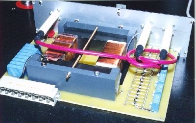
TEKNILLINEN KORKEAKOULU                                      LISENSIAATTITYÖN TIIVISTELMÄ

 Tekijä:               Marco Denicolai

 Työn nimi:            Koe- ja tutkimustoimintaan tarkoitettu Tesla-muuntaja

 Title in English:     Tesla Transformer for Experimentation and Research

 Päivämäärä:           30 May 2001                         Sivumäärä: 96

 Osasto/Laitos:        Sähkö- ja tietoliikennetekniikka    Professuuri: Sähkömekaniikka

 Työn valvoja:         Prof. Tapani Jokinen

 Työn ohjaaja(t):      Dos. Martti Aro

 Tesla-muuntaja on sähkölaite, joka pystyy tuottamaan suuria potentiaaleja; muutamista
 sadoista kilovolteista muutamiin megavoltteihin. Jännite on vaihtojännite ja sen taajuus on
 50 – 400 kHz.

 Tesla-muuntaja on tiedeyhteisölle tuttu 1900-luvun alusta lähtien ja sitä on käytetty
 monessa sovelluksessa. Siitä huolimatta monet muuntajan käyttöön liittyvät ainutlaatuiset
 ilmiöt ja niiden teoria kaipaavat vielä lisätutkimuksia.

 Tämä työ keskittyy koe- ja tutkimustoimintaan tarkoitetun Tesla-muuntajan suunnitteluun ja
 rakentamiseen: tavoitteena on pienentää toimintaan vaikuttavien stokastisten ja
 tuntemattomien parametrien määrää.

 Aluksi Tesla-muuntajan ja siihen tarvittavan virtalähteen toteuttamisvaihtoehdot on tutkittu,
 jokaisen hyviä ja huonoja puolia on tarkasteltu. Seuraavaksi keskikokonen Tesla-muuntaja
 on suunniteltu ja rakennettu käyttämällä yleisesti saatavia komponentteja. Toimintateoria on
 kuvattu käyttämällä perinteistä lähestymistapaa sekä uusia näkökulmia.

 Tesla-muuntajasta on rakennettu malli, jonka pohjana on käytetty kauppallista simulaatio-
 ohjelmistoa sekä pääkomponenttien mittaustuloksia. Lopuksi malli on todettu
 käyttökelpoiseksi vertailemalla simulaatio- ja mittaustuloksia.

 Avainsanat:         Tesla-muuntaja, teslakuristin, CCPS, resonanssi

 Ei lainata ennen:                                 Työn sijaintipaikka:
This page intentionally left blank
PREFACE

      Undertake something that is difficult; it will do you good. Unless you try to do
      something beyond what you have already mastered, you will never grow.
                                                                   Ronald E. Osborn

This project has truly been a learning experience, being the first three lessons learned
patience, patience and again patience.

Special thanks (in no particular order) go to all those who contributed to the accomplishment
of this work:
  •   Mika Salkola, for initially turning my attention to Tesla Coils.
  •   My two kids, Taneli and Matias, for helping me winding Thor’s secondary coil (about
      1000 meters of copper wire).
  •   Martti Aro and Jari Hällström for their help and directions to get around problems.
  •   The High Voltage Institute staff at the HUT for their help in practical matters.
  •   Malcolm Watts, Antonio Carlos M. de Queiroz and Terry Fritz for helping me
      understanding the theory of operation of the Tesla Coil.
  •   Paul Nicholson and all members of the Tesla Secondary Simulation Group for their
      excellent research work in simulating the secondary coil.
  •   Bill Wysock for supplying the bulky primary capacitor and the rotating spark gap.
  •   Imatran Voiman Säätiö, for supporting this work by granting me a scholarship.
  •   All members of the Tesla mailing List for their support and interest during all the
      phases of Thor’s development.

   And, last but not least, thanks to my wife Kaija for understanding me when I was
transporting the big toroid on the top of my car, during my neverending coil winding
sessions, and for her support during all these “Tesla years”.

                                                          Marco Denicolai
                                                          Espoo, Finland, 24 May, 2001

                                                                                            i
This page intentionally left blank ii
LIST OF SYMBOLS AND ACRONYMS

                   LIST OF SYMBOLS AND ACRONYMS

AC                       Alternate Current
BJT                      Bipolar Junction Transistor
CCPS                     Capacitor Charging Power Supply
DC                       Direct Current
EMF                      ElectroMagnetic Force
IC                       Integrated Circuit
IGBT                     Insulated Gate Bipolar Transistor
GTO                      Gate Turn-Off Thyristor
HDPE                     High-Density Polyethylene
HUT                      Helsinki University of Technology
HF                       High Frequency
H.P.                     Horse Power
HV                       High Voltage
H/D                      Height/diameter ratio
               1
KAPTON                   Polyimide
MOS                      Metal Oxide Semiconductor
MOSFET                   Metal Oxide Semiconductor Field Effect Transistor
MTO                      MOS Turn-Off Thyristor
           2
MYLAR                    Polyester
OPAMP                    Operational Amplifier
PCB                      Printed Circuit Board
PTFE                     Polytetrafluorethylene
PVC                      Polyvinyl Chloride
Q                        Quality-factor, a‘figure of merit’ of an oscillating circuit
RF                       Radio Frequency
R.P.M.                   Revolutions Per Minute
TC                       Tesla Coil, Tesla Transformer, resonance transformer
               3
TEFLON                   Polytetrafluorethylene
THOR                     The Tesla Coil built within this thesis
VARIAC                   Variable transformer

1
  Kapton is a registered trademark of DuPont
2
  Mylar is a registered trademark of DuPont
3
  Teflon is a registered trademark of DuPont

                                                                                              iii
This page intentionally left blank iv
CONTENTS

                                                       CONTENTS
LIST OF FIGURES................................................................................................................... VII
LIST OF TABLES...................................................................................................................... IX
1.        INTRODUCTION........................................................................................................... 1
     1.1. Structure of this thesis ....................................................................................................... 1
     1.2. Nikola Tesla ...................................................................................................................... 1
     1.3. The Tesla Coil ................................................................................................................... 2
     1.4. Applications ...................................................................................................................... 3
          1.4.1. Testing of insulating materials .............................................................................. 3
          1.4.2. Testing of insulators ..............................................................................................4
          1.4.3. Generation of high-voltage pulses......................................................................... 4
          1.4.4. Research on lightning discharges .......................................................................... 4
     1.5. Previous work.................................................................................................................... 4
     1.6. Project goals ...................................................................................................................... 6
2.           TESLA COIL TOPOLOGIES AND VARIATIONS...................................................8
     2.1.    Simplified theory of operation ..........................................................................................8
     2.2.    Alternative coupling schemes ......................................................................................... 10
             2.2.1. 3-coils, inductive coupling ..................................................................................10
             2.2.2. 3-coils, series feed ............................................................................................... 10
     2.3.    Static vs. rotary spark gap ...............................................................................................11
     2.4.    AC vs. DC power supply................................................................................................. 11
     2.5.    DC power supply topologies ........................................................................................... 12
             2.5.1. Conventional stabilized DC power supply.......................................................... 13
             2.5.2. DC power supply employing a high-voltage switch element .............................. 14
             2.5.3. High-frequency converter.................................................................................... 15
     2.6.    Effect of increased pulse rate .......................................................................................... 16
     2.7.    Pulsed vs. continuous wave............................................................................................. 16
     2.8.    Tesla Coil physical dimensions....................................................................................... 17
3.           DESIGN SPECIFICATION AND MAIN SOLUTIONS........................................... 18
     3.1.    Excitation mode and topology......................................................................................... 18
     3.2.    Spark gap selection.......................................................................................................... 18
     3.3.    Power supply selection....................................................................................................18
     3.4.    Power supply requirements .............................................................................................20
     3.5.    Tesla Coil dimensions ..................................................................................................... 22
     3.6.    Material selection ............................................................................................................ 22
4.           TESLA COIL DESIGN ................................................................................................24
     4.1.    General ............................................................................................................................ 24
     4.2.    Secondary design............................................................................................................. 25
     4.3.    Top terminal design......................................................................................................... 26
     4.4.    Primary capacitor choice ................................................................................................. 26
     4.5.    Primary design................................................................................................................. 27
     4.6.    Filter design..................................................................................................................... 28
5.        POWER SUPPLY DESIGN ......................................................................................... 29
     5.1. System design.................................................................................................................. 29
     5.2. High-frequency converter................................................................................................ 30
          5.2.1. Theory of operation ............................................................................................. 30

                                                                                                                                             v
CONTENTS
5.2.2. Bridge switch design............................................................................................34
5.2.3. Resonant load design ...........................................................................................36
5.2.4. Step-up transformer design..................................................................................36
5.3. High voltage probe ..........................................................................................................41
5.4. Controller.........................................................................................................................42
5.5. Module interconnection and auxiliary circuitry...............................................................44
5.6. Assembly and mechanics.................................................................................................44
6. TESLA COIL MODELING AND MEASUREMENTS ............................................48
6.1. Detailed theory of operation ............................................................................................48
6.1.1. Air-coupled resonant circuits...............................................................................48
6.1.2. Conditions for maximum voltage gain ................................................................51
6.1.3. Conditions for complete energy transfer..............................................................55
6.1.4. Inductance and capacitance of a close-wound solenoid.......................................58
6.2. Measurement results ........................................................................................................63
6.2.1. Secondary circuit components .............................................................................63
6.2.2. Primary circuit components .................................................................................64
6.2.3. Secondary voltage waveform...............................................................................66
6.3. Simulation model.............................................................................................................68
6.3.1. Secondary coil simulation....................................................................................68
6.3.2. Spark gap simulation ...........................................................................................71
6.3.3. Overall simulation model ....................................................................................73
6.4. Comparison of measurement against simulation results .................................................75
7. CONCLUSIONS AND FUTURE WORK...................................................................77
7.1. Conclusions .....................................................................................................................77
7.2. Future work......................................................................................................................78
REFERENCES ............................................................................................................................79
viLIST OF FIGURES
LIST OF FIGURES
Figure 1: Portrait of Nikola Tesla............................................................................................. 2
Figure 2: “Apparatus for transmitting electrical energy” [Tes14]............................................ 2
Figure 3: Tesla’s first air-cored transformer [Tes91]. .............................................................. 5
Figure 4: Another version of Tesla’s air-cored transformer [Tes94]. ...................................... 5
Figure 5: Tesla Coil basic schematic diagram.......................................................................... 8
Figure 6: Inductively coupled primary and secondary circuits in a TC.................................... 9
Figure 7: Top terminal voltage for a single spark gap pulse. ................................................... 9
Figure 8: From left to right, basic TC, 3-coil inductively coupled TC and 3-coil series feed
TC. ........................................................................................................................ 10
Figure 9: MicroSim model of a conventional DC power supply. .......................................... 13
Figure 10: MicroSim simulation results for the conventional power supply......................... 14
Figure 11: Power supply employing a high-voltage switch. .................................................. 14
Figure 12: Power supply employing a high-frequency converter. ......................................... 16
Figure 13: Series-loaded resonant converter.......................................................................... 19
Figure 14: Maximum available pulse peak voltage vs pulse rate. ......................................... 21
Figure 15: Maximum power provided to the Tesla Coil vs pulse rate................................... 21
Figure 16: Power supply architecture..................................................................................... 29
Figure 17: Basic block diagram of one converter module. .................................................... 30
Figure 18: Series-loaded resonant converter.......................................................................... 31
Figure 19: MicroSim simulation of the SLR converter. ........................................................ 32
Figure 20: SLR converter simulation waveforms. ................................................................. 32
Figure 21: Converter full-bridge schematic diagram. ............................................................ 35
Figure 22: Simulation of transformer primary voltage and current at charge beginning (left)
and end (right). ..................................................................................................... 38
Figure 23: Simulation of the transformer current (lower trace) and of its voltage integrated
over time (upper trace). ........................................................................................ 39
Figure 24: High voltage probe schematic diagram. ............................................................... 42
Figure 25: CCPS controller module schematics. ................................................................... 43
Figure 26: CCPS modules’ interconnection........................................................................... 44
Figure 27: The CCPC rack housing. ...................................................................................... 45
Figure 28: One of the plug-in converter modules. ................................................................. 45
Figure 29: Resonant load PCB assembly. .............................................................................. 46
Figure 30: The resonant load assembled in its plug-in frame. ............................................... 46
Figure 31: Primary winding organization. ............................................................................. 47
Figure 32: Secondary winding organization. ......................................................................... 47
Figure 33: Inductively coupled primary and secondary circuits in a TC. .............................. 48
Figure 34: G/GL gain vs. tuning ratio T for different m values [Phu91]................................ 52
Figure 35: K1 gain vs. tuning ratio T for different m values.................................................. 53
Figure 36: Total energy transfer after 10 primary cycles (see cursor) with k=0.161, in
correspondence of the second notch. .................................................................... 57
Figure 37: Energy transferred and transfer time vs. coupling coefficient.............................. 58
Figure 38: Modeling of the secondary coil capacitances [Nic00].......................................... 59
Figure 39: Primary circuit resonance frequency vs. primary coil tap position....................... 64
Figure 40: Primary and secondary coils coupling coefficient vs. primary elevation. ............ 65
Figure 41: Primary coil inductance vs. tap position.............................................................. 66
Figure 42: Typical secondary voltage waveform, with four beats. ........................................ 67
Figure 43: Zoomed first two beats from Figure 42. ............................................................... 67
viiLIST OF FIGURES Figure 44: Another secondary voltage waveform sample. .....................................................67 Figure 45: A third secondary waveform sample, with three beats only. ................................67 Figure 46: Secondary voltage waveform when leaders are produced. ...................................68 Figure 47: Secondary voltage waveform with a ground discharge. .......................................68 Figure 48: Cint(x,y) for y=10 vs. coil position.......................................................................68 Figure 49: Cext(x) vs. coil position........................................................................................68 Figure 50: Module and phase of the secondary coil base impedance vs. frequency. .............69 Figure 51: Voltage gain of the secondary coil vs. frequency. ................................................70 Figure 52: Voltage and current distribution (module) of the secondary coil at 66.49 kHz....70 Figure 53: Voltage and current distribution (phase) of the secondary coil at 66.49 kHz.......70 Figure 54: Voltage gradient of the secondary coil along its height........................................71 Figure 55: Spark gap simulation model. ................................................................................72 Figure 56: Transfer function of the spark gap simulation model (Iscale=0.01, Rscale=1). ........73 Figure 57: Thor’s overall simulation model...........................................................................74 Figure 58: Measured secondary voltage waveform (unloaded condition). ............................76 Figure 59: Simulated secondary voltage waveform. ..............................................................76 viii
LIST OF TABLES

LIST OF TABLES
Table 1:    Absolute maximum ratings for the IRG4PH40UD device ..................................... 34
Table 2:    Transformer design specification............................................................................ 37
Table 3:    Characteristics of the U100/57/25-3C90 core ........................................................ 37
Table 4:    Maximum gain as a function of tuning ratio and coupling coefficient [Phu91]..... 55
Table 5:    Some of the values of k that ensure complete energy transfer if T=1 [Deq02] ...... 56
Table 6:    Primary circuit resonance frequencies .................................................................... 64
Table 7:    Primary and secondary coils coupling coefficient .................................................. 65
Table 8:    Primary coil inductance vs. tap position ................................................................ 66
Table 9:    Predicted and measured secondary resonance frequencies ..................................... 71
Table 10:   Predicted equivalent reactances at 66.49 kHz......................................................... 71

                                                                                                                         ix
This page intentionally left blank x
INTRODUCTION                                                                Structure of this thesis

1.      INTRODUCTION
The Tesla Transformer is a fascinating device capable of creating spectacular effects: by
generating high-voltage pulses with several megavolts of amplitude, it emits electrical
discharges that easily extend for several meters and remind natural lightning.
  The Tesla Transformer has been known for more than a century to the scientific
community and also used in several applications. A significant amount of papers, articles and
books have been written about its theory of operation and its practical construction.
   Still, nearly every university high-voltage laboratory and technology museum strives to
own a Tesla Transformer, because some of the effects involved with its operation are pretty
unique to this kind of device and the theory underneath them still deserves a certain amount
of research to be fully explained and justified.
   On January 1999 the construction of a medium-sized Tesla Transformer was started at the
High Voltage Institute of the Helsinki University of Technology (HUT). The Tesla
Transformer to be built was named “Thor”, after the god from the Nordic mythology who
was capable of emitting lightning from its powerful hammer.

1.1.    Structure of this thesis
Chapter 1 provides the reader with the minimal amount of background needed to understand
the context of this thesis and the reasons why this project was undertaken. First a basic
biography of Nikola Tesla, the inventor of the Tesla Transformer, is presented. Then an
introduction to the Tesla Transformer and its main applications is given. Finally, the previous
work in this area is concisely reviewed and the project goals are stated.
   Chapter 2 is a review of the different possibilities to build a Tesla Transformer, with a
discussion of the benefits and penalties implied by each solution. Reading of this chapter
helps to understand the choices made in Chapter 3 for building Thor and its power supply.
   Chapter 4 reports the mathematical procedure used to design the main components of Thor
(primary coil, secondary coil, etc.) and Chapter 5 is a detailed description of Thor’s switching
power supply. In Chapter 6 the theory of operation of the Tesla Transformer is described in
detail: a simulation model is built and its validity is tested against actual measurements.
Finally, Chapter 7 lists the conclusions and outlines the research plans for the future.

1.2.    Nikola Tesla
Nikola Tesla was born in Smijlan, Croatia in 1856. He attended the Technical University of
Graz, Austria, and the University of Prague (1879-1880). His first employment was in a
government telegraph engineering office in Budapest, where he made his first invention, the
loudspeaker. In 1882 Tesla went to work in Paris for the Continental Edison Company, and
constructed his first induction motor.
   Tesla moved to America in 1884. In May 1885, George Westinghouse, head of the
Westinghouse Electric Company in Pittsburgh, bought the patent rights to Tesla's polyphase
system of alternating-current dynamos, transformers, and motors. In 1887 Tesla established
his own laboratory in New York City, where he performed countless experiments including
work on a carbon button lamp, on the power of electrical resonance, and on various types of
lighting. Tesla also invented the fluorescent lights and a new type of steam turbine.

Tesla Transformer for experimentation and research                                                     1
The Tesla Coil INTRODUCTION
A controversy between alternating current and direct current advocates raged in 1880s and
1890s, featuring Tesla and Edison as leaders in the rival camps.
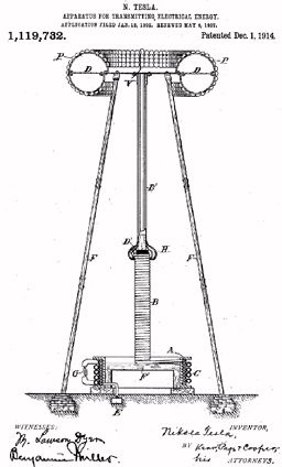
Figure 1: Portrait of Nikola Tesla. Figure 2: “Apparatus for transmitting
electrical energy” [Tes14].
In Colorado Springs, where he stayed from May 1899 until early 1900, Tesla made what
he regarded as his most important discovery - terrestrial stationary waves. By this discovery
he proved that the earth could be used as a conductor and would be as responsive as a tuning
fork to electrical vibrations of a certain pitch. In this period he also conducted the majority of
experiments intended to develop a way to wirelessly transmit electrical energy to consumer
appliances.
Tesla had a way of intuitively sensing hidden scientific secrets and employing his
inventive talent, but was quite impractical in financial matters. Returned to New York in
1900, because of a lack of funds, his ideas kept remaining in his notebooks, which are still
today examined by engineers for unexploited clues. He died in 1943, the holder of more than
100 patents.
1.3. The Tesla Coil
Among Tesla’s inventions, the resonance transformer occupies a place of its own. Originally
named as “Apparatus for transmitting electrical energy” in its patent [Tes14] dated 1914
(Figure 2), it was intended for transferring electrical energy without wires to lamps and
possibly other devices. Following the original Tesla’s concept, the emission of electrical
discharges from the top of the transformer was an unwanted effect that he considered as the
release of a “security valve”. The Tesla resonance transformer is nowadays better known as
Tesla Coil or simply resonance transformer. In the rest of this paper the Tesla Coil will be
referred to as TC.
A TC is an electrical device capable of developing high potentials typically ranging from a
few hundreds of kilovolts up to several megavolts. The voltage produced is AC, being the
voltage frequency typically 50 - 400 kHz. TCs are typically operated in pulsed mode, with
pulse widths varying from some nanoseconds up to several hundreds of microseconds
according to the particular application.
2 Marco DenicolaiINTRODUCTION Applications
In its simpler configuration, a TC is composed by two air-cored coils, named primary and
secondary coils. While in conventional metal- and ferrite-core transformers the primary and
secondary voltage ratio is directly related to the windings number of turns ratio, the output
voltage of a TC it is related to primary and secondary inductance ratio.
Different groups of people have been interested in Tesla Coils during all the past century:
• In the first half of the 20th century industry have manufactured small-sized TCs to
generate high-voltage for a number of classical applications (X-ray generators,
electrocution and coagulation for veterinary purposes, etc.). Nowadays the TCs used in
most of these applications have been replaced by conventional technology using
discrete electronic components.
• Research groups have replicated Tesla’s original TC designs and produced new ones,
according to the increasing number of materials becoming available (plastics and
insulators in general). Many attempts have been made to complete the rudimental
measurements Nikola Tesla originally performed and provide a robust and proven
mathematical model covering all operational principles of TCs.
• The spectacular leader inceptions produced by TCs, that closely remind downsized
natural lightning, has attracted the film industry from its very beginning. TCs are still
today manufactured and used to produce special effects in movies and theatre shows.
• TCs have fascinated a number of hobbyists all around the world that have engaged in
building low-cost, small- and medium-sized TCs in their garages. These individuals
have had an enormous influence in the demolition and replacement of existing
theories about TC operational principles.
1.4. Applications
Nowadays, applications for Tesla Coils fall within the following categories.
1.4.1. Testing of insulating materials
Insulation materials used in high-voltage switched-mode power supplies are exposed to high
frequency high voltages. Traditional tests performed with high DC voltages might not reveal
the true aging effects occurring during rated operation; successful experiments have been
conducted using high-frequency, high-voltage power sources [Har98].
Cored transformers are not preferred for generating high test voltages at high frequencies,
since they must employ ferrite instead of iron and therefore are quite costly for the power
required by these applications. Furthermore, the reactive power needed by the capacitive load
of the sample under test has to pass also through the transformer and be supplied to it.
Ferrite-cored resonance transformers have small dimensions but a comparatively high
stray capacitance that is in the order of the sample capacitance. The ferrite core also produces
high flux non-linear effects that result in unacceptable harmonics.
The Tesla Coil avoids non-linear effects because it is air-cored. As the size of its coils is
bigger, the distance between its windings can be bigger as well, so that the stray capacitance
becomes smaller. Options are available to increase the test voltage level and to modify the
voltage frequency.
Tesla Transformer for experimentation and research 3Previous work INTRODUCTION 1.4.2. Testing of insulators Although it is difficult to control the generated wave-shapes, the damped high frequency oscillations of Tesla Coils are somewhat similar to typical transient disturbances found in power systems (e.g. caused by switching operations or by arcing to ground). Manufacturers of ceramic insulators are still using TCs as a test source in routine tests for puncture withstand. They are also employed for generic insulator testing [Phu91] and synthetic testing of circuit breakers [Dam87]. 1.4.3. Generation of high-voltage pulses Sources of short high-voltage pulses with high repetition rate are considered to be of interest for a number of problems. For instance, they can be used to generate electromagnetic radiation to measure objects to a high precision or powerful microwave pulses with 3-cm wavelength [Gub97]. Numerous papers have been published with particular emphasis on the use of a TC in relativistic electron beam generators [Hof75, Mat82]: its main advantages over the Marx generator are high repetition rates of operation and low cost because of the lower number of capacitors used. Tesla Coil use is also reported in a series of compact and portable devices to drive cold- cathode e-beam tubes and X-ray tubes [Mes95]; applications include express spectral analysis of minerals and jewels, as well as rapid radiography on-field. 1.4.4. Research on lightning discharges Research on natural lightning has been motivated by the desire to prevent spectacular accidents, such as occurred in 1969 during the launch of Apollo 12 [God70] and in 1987 during the launch of Atlas-Centaur 67 [Bus87]. While cloud-to-ground lightning has been studied more extensively, cloud-to-cloud and cloud-to-air discharges still need to be understood more thoroughly as they are more difficult to be measured [Uma87]. Field observations of lightning can reveal directly little of the physics of the phenomenon; the propagation process and the leader velocity are best studied by scaling of laboratory sparks [Les77, Les81]. In pre-war work Allibone and Meek had succeeded to demonstrate the existence of a laboratory analogue to the lightning stepped leader discovered by Schonland in 1933 [Wat96]. 1.5. Previous work The first record of Tesla’s air-cored transformer is dated 1891 and appeared in one of his patents [Tes91], where the high voltage developed was intended to be used for electric lighting. The circuit converted low frequency currents into “currents of very high frequency and very high potential” which then supplied single terminal lamps (Figure 3). A much more refined version of the same circuit appeared in a subsequent patent [Tes94], where the spark gap had been moved in parallel to the feeding power supply and the primary capacitor had been split in two (Figure 4). Nikola Tesla, as he quoted in some of his patents, tested a huge number of circuital variations along several years, but patented only a few of them. The first mathematical analysis of Tesla’s air-cored transformer is due to Oberbeck [Obe95]: he treated the transformer as two air-coupled resonant circuits and covered thoroughly the case where the two circuits are tuned to resonate at the same frequency. In a later paper, dated 1904, Drude [Dru04] pointed out the conditions required to achieve the 4 Marco Denicolai
INTRODUCTION                                                                         Previous work

 maximum voltage at the secondary circuit (that is, a unitary tuning ratio but a coupling
 coefficient of 0.6).

Figure 3: Tesla’s first air-cored                     Figure 4: Another version of Tesla’s air-
          transformer [Tes91].                                  cored transformer [Tes94].

    A series of presentations of the air-coupled resonant circuits theory appeared in a number
 of books and papers all along the last century. These analysis are basically similar to each
 other, differing only in the level of detail or the degree of clearness. Some of the classical
 references are listed below:
    •   Terman [Ter43], with a pragmatic view of the influence of Q factor and coupling
        coefficient on the energy transfer efficiency.
    •   Smythe [Smy50], giving a thorough (but someway complicated) analysis of lossy and
        lossless circuits.
    •   Craggs & Meek [Cra54], providing straightforward results.
    As only the case of ideal (i.e. lossless) circuits could be solved in a closed form, the lossy
 case was always tabulated or presented as family of curves [Ter43], only recently produced
 by using computer algorithms ([Hof75, Mat82, Hit83]).
    The search for an optimal working point of the Tesla Coil evolved along two axis,
 targeting either the maximum output voltage or a complete energy transfer from the primary
 to the secondary circuits. In 1988, Reed [Ree88] observed that an 18% increase in voltage
 could be obtained by using a tuning ratio less than unity and a suitable amount of coupling.
 Reed’s work was generalized in 1991 by Phung et al. [Phu91] that provided a set of equations

 Tesla Transformer for experimentation and research                                                   5
Project goals INTRODUCTION
in order to calculate all tuning ratio and coupling coefficients pairs that achieved a (local)
maximum output.
In 1966, Finkelstein [Fin66] identified the general conditions required for a complete
energy transfer from the primary to the secondary circuits: in all cases, a unitary tuning ratio
was required. The Drude’s conditions turned out to achieve complete energy transfer in the
least time, but other values of coupling coefficient could also be used, while the transfer
completion got simply moved to a later time instant.
Finkelstein’s work was continued and extended to three coupled resonance circuits by
Bieniosek [Bie90] and eventually generalized to any number of circuits by de Queiroz
[Deq00, Deq01]. The importance of these works is that they can be easily applied to the
particular case of the Tesla Coil (two-circuit case) in order to obtain complete energy transfer
and, therefore, a better efficiency.
The previous work dealing with Tesla Coils provides only partial views of the whole
theory of operation involved. All the papers aimed at maximizing the voltage developed at
the top terminal, or at achieving a complete energy transfer, use a simple lumped-element
model for the secondary circuit. In some rare case the coil and its top load have been modeled
using transmission line theory [Cor87, Cor99]. Both approaches have shown (or pretended to
show) a good match with experimental results, while starting from a controversial view of the
phenomena. This difference of view has started a long debate among different parties,
involving merely hobbyists and being ignored by the scientific community.
Descriptions of TC construction details can only be found in material written by hobbyists
and justification of the solutions adopted is often missing or based on rules-of the-thumb. A
reference that encompasses all the parts of a TC, following the energy transformations from
the power supply to the leader inception into free air is missing.
1.6. Project goals
The goal of this project is to design and build a medium-sized Tesla Coil suitable for
performing experiments and measurements in a rational and controlled manner. This can be
achieved if the following requirements are satisfied:
• The TC is constructed according to design drawings; dimensions are well known and
an accurate modeling is possible.
• The TC size is sufficient to easily allow for insertion of measurement transducers
(current probes, field probes, etc.) without being noticeably disturbed by the losses
introduced by them.
• The characteristics of all components have been (directly or indirectly) measured in
advance.
• A model of the whole TC has been created and used for simulations, and the
experimental data match simulation results.
• The power supply used to feed the TC allows charging the primary capacitor to a
repeatable, predefined potential within a known time: practical experience suggests
that a target voltage of 10 to 20 kV might be appropriate. The charging voltage is
independent from the capacitor discharge frequency (pulse repetition rate) to allow a
separated regulation of these two parameters.
• The pulse repetition rate is stable, extending over the 200 Hz typically found in today’s
TC designs up to at least 500 Hz. Nikola Tesla used a pulse rate of over 2400 Hz in his
own experiments, together with an average power of about 15 kVA [Tes78, Hul93].
6 Marco DenicolaiINTRODUCTION Project goals For instance, a subsequent research work could investigate on the elongation of the ramified discharges emitted by the TC and its relationship to the operational parameters, as it is well known that these discharges are noticeably longer than what is expected based on simple considerations. Tesla Transformer for experimentation and research 7
Simplified theory of operation                         TESLA COIL TOPOLOGIES AND VARIATIONS

2.      TESLA COIL TOPOLOGIES AND VARIATIONS
In the literature, the name “Tesla Coil” has been traditionally used for quite a range of
different devices, being the only common thread that air-coupled resonant circuits were
involved and a high-voltage was developed. The purpose of this chapter is to give an
overview of the many ways a Tesla Coil can be built, pointing out the major pros, cons or
simply the consequences caused by adopting different solutions for each component.
   First, a simplified theory of operation of the TC is presented, together with the typical
three feeding topologies. Then the choice for the TC power supply is analyzed and different
solutions for its implementation explored. Finally, the effect of the excitation method (pulsed
or continuous) and the influence of the TC physical size are discussed.

2.1.    Simplified theory of operation
A Tesla Coil can be built using only a few basic components (Figure 5). A transformer
generates a high voltage (typically 5 – 30 kV) from the mains that charges the primary
capacitor C through the primary coil LP. LP is composed by a few turns (5 – 20) of heavy
copper wire having a very low resistance.

                                     HV TRANSFORMER      C

                                                                    LS
                                               SPARK         LP
                                                GAP
                             MAINS

                 Figure 5: Tesla Coil basic schematic diagram.

   When C is sufficiently charged, the potential difference between the spark gap electrodes
becomes sufficient for the gap to fire and allow current to pass through. While the gap is
conducting, C is connected in parallel to LP and gets discharged into it. C and LP form a
parallel resonant circuit with a resonance frequency defined by their capacitance and
inductance values.
   The magnetic field generated by LP is partly induced into the secondary coil LS. LS is
composed by about 1000 turns of thin copper wire and its top lead is connected to a spherical
or toroidal terminal with a capacitance of typically 15 – 30 pF. LS and its top terminal form a
resonant circuit. If its resonance frequency is near to the one of the primary circuit, an
extremely high potential is developed at the top terminal.
   As the secondary can easily reach potentials ranging from 100 kV to several MV, the
electric field generated is usually sufficient to breakdown the surrounding air dielectric
releasing a leader inception. Once the capacitor C gets completely discharged, the spark gap
stops conducting and the same process already described repeats again.
   The operation of a TC is governed by the mathematical laws describing two air-cored,
inductively coupled resonant circuits [Ter43, Smy50]. The first circuit is formed by the
primary capacitor C and primary coil LP connected in series through the spark gap, while the
second circuit is constituted by the secondary coil LS in series with the top terminal acting as
a capacitance connected to ground (Figure 6).

8                                                                                 Marco Denicolai
TESLA COIL TOPOLOGIES AND VARIATIONS Simplified theory of operation
SECONDARY
PRIMARY
CIRCUIT
CIRCUIT
LS
LS
C
C LP
LP
Figure 6: Inductively coupled primary and secondary circuits
in a TC.
As the spark gap closes, the energy stored in the primary capacitor C feeds LP; the primary
circuit oscillates close to its resonance frequency defined by the values of C and LP4. Part of
this energy is magnetically coupled into the secondary LS that, in turn, oscillates close to its
own resonance frequency too. The amplitude of the resultant oscillation is at a maximum
when these two are in phase; this produces the phenomenon of beats5 like those observed in
water and sound waves (see the example in Figure 7).
The energy transfers back and forth from one circuit to the other with this beat frequency
until it is entirely dissipated in resistive and RF losses; at this time the current in the primary
circuit is minimal and the spark gap opens.
5
x 10
8
k = 0.20
6
4
Top terminal voltage [V]
2
0
-2
-4
-6
-8
0 1 2 3 4 5 6
Time [s] x 10
-4
Figure 7: Top terminal voltage for a single spark
gap pulse.
The ratio between the voltage applied to LP and the one developed on LS is not dependent
on the turn ratio between primary and secondary coils but is instead directly proportional to
the square root of the ratio of LS and LP inductance. The coupling coefficient between the
two coils is also quite different from the usual values of 0.9 - 1 used in traditional iron-core
transformers: typical values range from 0.1 to 0.6.
4
The oscillation frequency depends also on other parameters because the primary is magnetically coupled to the
primary. A complete treatment of this matter can be found in Chapter 6.1.1.
5
Within this thesis, the term beat is used for an amplitude modulated carrier to indicate an interval between two
successive points where the signal amplitude is zero. For instance, six beats can be identified in Figure 7.
Tesla Transformer for experimentation and research 9Alternative coupling schemes TESLA COIL TOPOLOGIES AND VARIATIONS
2.2. Alternative coupling schemes
In the basic 2-coil TC presented in Figure 5, the energy from the primary circuit is transferred
to the secondary by inductive coupling. A series of different solutions for transferring the
primary circuit energy have been investigated by Nikola Tesla himself and replicated during
the years with success by experimenters.
2.2.1. 3-coils, inductive coupling
This connection scheme is known among hobbyists as “magnifier” and employs what Nikola
Tesla named as the “extra coil”. The basic idea (Figure 8) is to move the most of the
traditional secondary coil relatively far away from the magnetic field generated by the
primary; the secondary is reduced to a few turns tightly coupled to the primary (coupling
coefficient used is about 0.6).
The voltage rise-up in the reduced secondary is now governed by the turn ratio, as in a
usual transformer. The top of the secondary is used to series feed the “extra coil”, where the
voltage built is still due to resonant charging.
In several TCs, the top terminal height practically limits the potential they can develop: the
terminal can easily arch to the nearby primary coil or directly to the floor. Using this TC
configuration, the top terminal (together with the extra coil) can be elevated far from any
grounded point thus avoiding any leader inception to ground.
Anyway, the assembly is made more difficult by the need to provide high inductive
coupling between primary and secondary while still keeping a good insulation between the
two of them. The tight coupling requires a rugged and fast rotary spark gap to avoid
dissipating all the energy in losses during transfers between primary and secondary circuits.
"EXTRA" "EXTRA"
"EXTRA"
COIL "EXTRA"
COIL
COIL COIL
SECONDARY
PRIMARY
PRIMARY COIL
SECONDARY
COIL COIL
COIL SECONDARY
SECONDARY
SECONDARY COIL
COIL
PRIMARY SECONDARY
PRIMARY
COIL COIL
COIL
COIL PRIMARY
PRIMARY
COIL
COIL
Figure 8: From left to right, basic TC, 3-coil inductively coupled TC and 3-coil
series feed TC.
2.2.2. 3-coils, series feed
This connection scheme differs from the previous as the primary coil is connected in series
and also inductively coupled to the secondary; primary and secondary therefore implement an
autotransformer that series feeds the extra coil. The two windings don’t need anymore to be
insulated but the requirements for the spark gap are still quite strict.
10 Marco DenicolaiTESLA COIL TOPOLOGIES AND VARIATIONS Static vs. rotary spark gap
2.3. Static vs. rotary spark gap
The simplest solution for the spark gap is a static couple of electrodes separated by a suitable
dielectric (usually a dry gas mixture including SF6, Nitrogen, etc.). Spark-over occurs when a
voltage threshold is exceeded and the arc self-extinguish when the current passing through
the gap decreases below a certain value.
Commercial spark gaps usually employ also a trigger electrode to provide an initial
ionization of the dielectric and facilitate its breakdown between the two main electrodes. This
way it is possible to control the exact spark repetition rate, as required by radars, lasers, etc.
Strict constraints are placed on the triggering pulse rise time, duration and amplitude, usually
required to be 100% of the switched voltage.
The high current flowing in the primary circuit of a typical middle-sized TC is capable of
quickly warm-up these static spark gaps: water or other kind of cooling is thus required.
Using a series of multiple static gaps results in an even heat distribution and can partly reduce
this problem; the spread between the minimum and maximum triggering voltage is anyway
worsened by the connection.
For an optimal Tesla Coil performance, the gap is also required to stop conducting without
re-igniting; the ionized dielectric gas mixture must be renewed after each pulse, maintaining a
suitable pressure inside the gap. Vacuum or sealed static spark gaps are not suitable for TC
use because they require a recovery time of several milliseconds between pulses.
Commercial static spark gaps are expensive to purchase and also to operate, while their
construction with conventional amateur techniques is almost impossible. In practice, simple
two or multiple electrode spark gaps with air dielectric are viable for small-sized TCs where
switched power doesn’t exceed 2 kW. Ionized air is removed from the gap by using
compressed air or vacuum suction.
Rotary spark gaps represent a solution to several of the above mentioned problems: being
engineered in different configurations, they basically consist of a set of stationary electrodes
and a set of rotating ones. When a rotating electrode comes in proximity of the static ones
their clearance is at a minimum and spark-over occurs.
Rotary spark gaps can be easily manufactured by using brushless motors or DC motors
when a variable pulse rate is required. Static electrodes are cooled by providing them with
proper heat sinks, while moving electrodes usually don’t get even sensibly warm. By using
fast rotating speeds there is no need of removing ionized dielectric and high pulse rates can
be easily achieved.
2.4. AC vs. DC power supply
The basic TC described in Figure 5 employs an AC power supply; the rate of the pulses
generated by the spark gap closures is related to its triggering voltage. If this voltage is
slightly lower than the supplied peak voltage, the pulse rate is equal to the AC supply
frequency (50 or 60 Hz) as there is only one pulse for each cycle.
A decrease in the spark gap triggering voltage allows for a higher pulse rate but the TC
operation gets much more complicated. Note that when the spark gap is closed the power
supply is effectively short-circuited. At spark gap opening the primary capacitor charging
voltage depends on several factors:
• The power supply current capabilities.
• The instantaneous voltage value available from the mains (i.e. the temporal “phase “of
the previous pulse).
Tesla Transformer for experimentation and research 11DC power supply topologies TESLA COIL TOPOLOGIES AND VARIATIONS
• The spark gap triggering voltage, together with its intrinsic level of randomness.
The resulting functional mode makes performance optimization problematic. Practical
experience indicates that if the power used is higher than a few kilowatts, the use of rotary
spark gaps becomes mandatory. This adds one more uncertainty factor to the three listed
above: the temporal phase of the AC supply voltage in respect to the gap electrodes spark-
over.
On the other hand, the use of a rotary spark gap provides also a mechanism to control the
TC performance better than with a static one. This can be achieved in several ways:
1. The pulse rate dictated by the rotating spark gap is sensibly higher than the AC supply
frequency (e.g. 400 - 700 Hz). This way the phase relation between gap and supply
voltage becomes irrelevant, as the pulses are on average uniformly distributed.
2. The rotary spark gap employs a synchronous motor fed from the same AC voltage
used for the power supply. Gap and supply are thus in phase and a pulse rate equal to
an integer multiple of the supply frequency can be achieved. The phase angle can be
precisely set for the pulses to be distributed in an optimal area of the supply voltage
half cycle.
3. The power supply is replaced by an alternator driven by the same motor used for the
spark gap [Gla48]. The system can be designed so that the generated AC voltage
frequency is exactly equal to the gap pulse rate. Because the alternator and gap rotors
are mounted on the same motor shaft, a constant phase angle between them is
ensured.
While the above solutions allow for reaching a stable and optimal performance point, the
resulting amplitude of each single pulse is still not a constant; measurements of the coil
parameters are very difficult as each pulse should be analyzed as a unique entity.
A great simplification is introduced by using a stabilized DC power supply together with a
rotary spark gap. The pulse rate is solely defined by the spark gap rotation rate, provided that
the power supply is capable of providing enough current to charge the primary capacitor
between pulses. All pulses have the same amplitude, as the capacitor gets always charged to
the same voltage, while the spark gap phase and rotating speed do not need anymore to be
precisely controlled.
Under these conditions, parameter measurement is facilitated, at the expense of higher
complexity required for the design of a DC power supply.
2.5. DC power supply topologies
It is essential to excite the primary circuit with pulses having known amplitude; the primary
capacitor must always get charged to a stable, predefined voltage without fluctuations due to
the pulses phase or repetition rate. This way, measurements can be concentrated only on
tracking and modeling various parameters object of study without unnecessary complications.
This requirement, together with the high desired pulse rate of 500 Hz, put a special
emphasis on the selection of the power supply design. The requirements to be satisfied can be
specified as follows:
1. The primary capacitor must get charged before each pulse to an exact, known voltage.
2. This charging voltage must be adjustable, in order to obtain a range of different
operating conditions.
3. Maximum desired charging voltage is about 20 kV.
12 Marco DenicolaiYou can also read