DIY Audio Design Building and designing your own sonic tools.
←
→
Page content transcription
If your browser does not render page correctly, please read the page content below
DIY Audio Design
   Building and designing your own sonic tools.

           Alexander Bolk August 2011

Supportive narrative for the partial fulfillment of the
Master of Arts in Creative Design for Digital Cultures

           Sound and Music Technology
        Hogeschool voor de Kunsten Utrecht
         Faculty Art, Media and Technology

            Oude Amersfoortseweg 131
                  Postbus 2471
               1200 CL Hilversum
                   035-6836464
                 info@kmt.hku.nl
                  kmtweb.hku.nl

            Supervisor: Jorrit Tamminga
             Student number: 2061348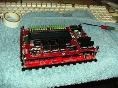

Contents:
1 Introduction 6
2 DIY music technology 7
2.1 D.I.Y culture . . . . . . . . . . . . . . . . . . . . . . . . . . . . . . . . . . . . . . . . . . . 7
2.2 evolution through revolution . . . . . . . . . . . . . . . . . . . . . . . . . . . . . . . . . 8
2.3 personal background . . . . . . . . . . . . . . . . . . . . . . . . . . . . . . . . . . . . . . 10
2.3.1 modification. . . . . . . . . . . . . . . . . . . . . . . . . . . . . . . . . . . . . . 11
2.3.2 kits and patches . . . . . . . . . . . . . . . . . . . . . . . . . . . . . . . . . . . . 13
2.3.3 circuits . . . . . . . . . . . . . . . . . . . . . . . . . . . . . . . . . . . . . . . . . 14
2.3.4 soware design . . . . . . . . . . . . . . . . . . . . . . . . . . . . . . . . . . . . 15
2.4 So, what is possible as a diy sound designer? . . . . . . . . . . . . . . . . . . . . . . . . 16
3 From modification to design 20
3.1 circuit bending . . . . . . . . . . . . . . . . . . . . . . . . . . . . . . . . . . . . . . . . . . 20
3.2 modification . . . . . . . . . . . . . . . . . . . . . . . . . . . . . . . . . . . . . . . . . . . 22
3.3 effect pedals . . . . . . . . . . . . . . . . . . . . . . . . . . . . . . . . . . . . . . . . . . . . 22
3.3.1 history. . . . . . . . . . . . . . . . . . . . . . . . . . . . . . . . . . . . . . . . . . 23
3.3.2 fuzz . . . . . . . . . . . . . . . . . . . . . . . . . . . . . . . . . . . . . . . . . . . 24
3.3.3 modulation and delay . . . . . . . . . . . . . . . . . . . . . . . . . . . . . . . . 25
3.3.4 experimentation . . . . . . . . . . . . . . . . . . . . . . . . . . . . . . . . . . . . 26
3.4 sound generators . . . . . . . . . . . . . . . . . . . . . . . . . . . . . . . . . . . . . . . . . 28
3.5 soware solutions . . . . . . . . . . . . . . . . . . . . . . . . . . . . . . . . . . . . . . . . . 30
3.5.1 soware prototypes . . . . . . . . . . . . . . . . . . . . . . . . . . . . . . . . . . 30
3.5.2 soware controllers . . . . . . . . . . . . . . . . . . . . . . . . . . . . . . . . . . 31
3.5.3 hybrids . . . . . . . . . . . . . . . . . . . . . . . . . . . . . . . . . . . . . . . . . 32
4. Applied tools and techniques 33
4.1 sound design. . . . . . . . . . . . . . . . . . . . . . . . . . . . . . . . . . . . . . . . . . . . 33
4.2 signal theory . . . . . . . . . . . . . . . . . . . . . . . . . . . . . . . . . . . . . . . . . . . 33
4.3 electronic engineering . . . . . . . . . . . . . . . . . . . . . . . . . . . . . . . . . . . . . . 34
4.4 soldering . . . . . . . . . . . . . . . . . . . . . . . . . . . . . . . . . . . . . . . . . . . . . . 34
4.5 programming . . . . . . . . . . . . . . . . . . . . . . . . . . . . . . . . . . . . . . . . . . . 35
4.6 interface design . . . . . . . . . . . . . . . . . . . . . . . . . . . . . . . . . . . . . . . . . . 36
4.7 artwork . . . . . . . . . . . . . . . . . . . . . . . . . . . . . . . . . . . . . . . . . . . . . . 37
3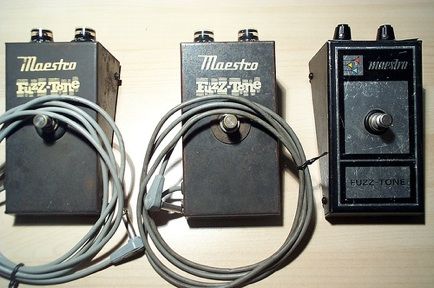
5 Evaluation                                                                                                                                                                              38
      5.1 results . . . . . . . . . . . .   .   .   .   .   .   .   .   .   .   .   .   .   .   .   .   .   .   .   .   .   .   .   .   .   .   .   .   .   .   .   .   .   .   .   .   . 38
              5.1.1 circuit Bending         .   .   .   .   .   .   .   .   .   .   .   .   .   .   .   .   .   .   .   .   .   .   .   .   .   .   .   .   .   .   .   .   .   .   .   . 38
              5.1.2 modification . .         .   .   .   .   .   .   .   .   .   .   .   .   .   .   .   .   .   .   .   .   .   .   .   .   .   .   .   .   .   .   .   .   .   .   .   . 41
              5.1.3 effect Pedals . .        .   .   .   .   .   .   .   .   .   .   .   .   .   .   .   .   .   .   .   .   .   .   .   .   .   .   .   .   .   .   .   .   .   .   .   . 42
      5.2 external review . . . . . .       .   .   .   .   .   .   .   .   .   .   .   .   .   .   .   .   .   .   .   .   .   .   .   .   .   .   .   .   .   .   .   .   .   .   .   . 46
      5.3 tools . . . . . . . . . . . . .   .   .   .   .   .   .   .   .   .   .   .   .   .   .   .   .   .   .   .   .   .   .   .   .   .   .   .   .   .   .   .   .   .   .   .   . 47
      5.4 techniques . . . . . . . . .      .   .   .   .   .   .   .   .   .   .   .   .   .   .   .   .   .   .   .   .   .   .   .   .   .   .   .   .   .   .   .   .   .   .   .   . 48
      5.5 failure and improvement.          .   .   .   .   .   .   .   .   .   .   .   .   .   .   .   .   .   .   .   .   .   .   .   .   .   .   .   .   .   .   .   .   .   .   .   . 49

6 Conclusion and future work                                                                                                                                                             51

Bibliography                                                                                                                                                                             53

Appendix A Links                                                                                                                                                                         55
Appendix B Interviews                                                                                                                                                                    57

                                                                        4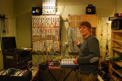
Abstract
is text is a description of the author's endeavors and research into building musical tools and
instruments with a so-called D.I.Y. approach. e projects and this text are part of the fulfillment
of the EMMA program at the Hogeschool voor de Kunsten in Utrecht.
e first chapter gives a brief definition of DIY culture within the context of the author's projects
and states his project goal and research question:
- What are the possibilities with diy as a professional sound designer?
In order to become a competent professional, it is essential to improve skills in arts and cras,
design, signal theory, math, physics and electrical engineering.
Documenting how much improvement and skills can be developed during the course of these
projects and interviewing several peers, the main motivation for the subject is a longstanding
interest in the diy culture within music technology.
Chapter 2 outlines the work-field related to the subject of diy music technology and gives a brief
overview of the author’s background.
Chapter 3 presents the world of diy in music technology today and some of it’s history and
illustrating the possibilities and advantages of diy opposed to the consumption of music
technology.
In chapter 4 the required techniques and tools for the projects are summarized.
Chapter 5 evaluates the projects and progress made by the author in relation to the research and
interviews.
e final chapter looks back at the complete project and will answer some of the problems
encountered in the practical work, suggest improvements for future work and assess the author as a
professional in the field.
In the appendix will be transcriptions of a number of the interviews done for the research and a list
of resources and links for further reading.
5
1. Introduction
D.I.Y. means ‘do it yourself ’.
Taking control of processes that used to be done by others, diy can be improving, repairing and
cloning existing technology, but most important to this text, diy means innovation.
From folding a piece of paper to support a wobbly table, to a rocket built in your shed, diy is
wherever technology and science is used and it is, and has always been part of our lives and it will
be the most relevant part of our lives in our technology dependent future.
Before the industrial revolution we applied technology the way we diy today. Civilization
depended on arts and crasmen and the economy thrived on trading technologies and goods.
As we evolved into the industrial revolution we became less dependent of arts and cras, but more
and more on industrial processes and storekeepers.
e 20th century saw this revolution blossom into the world we know today, we live in a world
where everything is connected by industrial and globally controlled processes, all powered by
western world economy. When a developing country gains economic significance, within the list of
third world countries we categorize them as ‘newly industrialized country’ ! (Toffler 1980)
e first and second world war forced electronics and industrial science and technology forward.
We became extremely advanced in only a few decades and aer the second world war we were le
with a brave new world of consumer electronics, highways, television and consumer marketing.
All this helped to shape music technology as we have it available to us today.
With the arrival of the internet we started a new revolution and today, almost 30 years later, we
start to see the consequences on technology and the world we live in.
DIY culture is an internet community sharing their work and knowledge through various websites
and media outlets on the world wide web. Remember the trading of arts and goods and
technology..
Because we have everything available to us all the time, instantly. We are le with few restrictions,
than money. But most of the significant innovations of the past were not motivated by money. So
although we have large quantities of diy projects and communities, ground breaking work is scarce.
My goal is to look into the world called diy. By being part of communities within music
technology, investigating what motivates the participating people. To see what future and impact
these communities can have as a whole in a world driven by fashion and mass consumption, rapidly
changing. Everyone is now part of the internet, and the social aspect is being formed and
combined with technological development and sharing of knowledge we are creating a culture that
is very similar to the world before the industrial revolution. Accelerated and virtual, but very
similar. I hope to get a clear picture of what is possible as a diy sound designer.
How do we use this new world, what can we do ourselves, as individuals and benefit from the
seemingly limitlessness of it all?
6
2. D.I.Y. music technology
2.1 D.I.Y culture
DIY is a broad term and so is ‘diy culture’ it expands from home improvement far into every field
of arts, cras and science. ere are however similarities to the way various forms of DIY evolved
within society over the past century and how common influences such as technological
advancements and the digital revolution brought a lot of them together and with the recent
decades of online sharing, diy has generated culture. (handmade nation, the rise of diy,
art, craft and design 2009)
With the greatest library of all available to us we now have access to information on all of those
developments, from the past to present. ere is enormous potential, but also a very negative and
chaotic side to the information highway. It can have an impact on your judgement and make you
less objective to a product’s qualities.
In electrical engineering we have data-sheets available to every part we can imagine, schematics on
most equipment available to us on the market. So without any undiscovered territory out there it
becomes very hard to use your imagination without a feeling you do it out of a necessity to be
original. When it comes to actually making an honest living on the internet, the lacking of
regulation and rules and it’s chaotic nature can makes it a lot like gambling. You can have a hit or
great success with the least effort and you can have your work float around there unnoticed. e
only rules that seem to apply to how the internet behaves can be found in the study of chaos.
(Lorenz 1993)
But out of chaos comes order and in the case of art, a lot of beauty and data can be extracted from
it. So as a community a group of DIY artists and individuals can truly make an impact and a
successful business. (see the interview with Tom Dalton of fuzzhugger effects, which is an
example of the above statement.)
An important difference between a commercial product and a diy product is it’s initial goal and the
impact they have on the music community.
“One is moving products, one is defining culture”
- From the documentary ‘I need that record’
7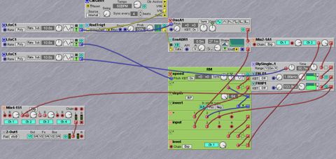
2.2 evolution through revolution
Music technology changed rapidly since the second world war le us with accelerated
developments in communication and electronic engineering. From radio-waves and tube
amplification, we entered the 1950’s with tape recorder and transistors and we are still basing most
of our recent work on the basic principles of those inventions. (http:/obsolete.com/120years.com)
And with current developments in surface mount electronic parts, we are limited to aging
techniques and parts for our electronic designs, for it is simply to complicated to stay up to date
technically, yet this doesn’t mean our designs are aging or not competitive with the current mayor
companies’ line of products.
is development of SMD electronic is an example of an evolution that does not necessarily
benefit the DIY sound designer, for it limits their technical capabilities against the commercial
technological standard. However the limitation and current retro popularity of instruments,
sounds and techniques from the past can be seen as an advantages and a chance to redesign not
only good designs from the past, but also make them available to a younger market. (From the
interview I did with engineer and electronic instrument designer Maarten
Halmans:)
“...in the longer future it will become harder for a lot of people, thru hole
technology(electronic components with leads) is becoming obsolete and and most
electronic parts will be surface mount. This makes it harder to get started in
diy because of the needed soldering skills. On the other hand it will become
easier and cheaper to do small runs of specific semiconductors and electronic
instruments.”
An accessible and relatively easy form of diy design is cloning existing technology. Schematics and
oen layouts for circuit boards are available to a lot of equipment, you can start building your own
ssl compressor (http://www.gyraf.dk/gy_pd/ssl/ssl.htm) or serge modular synthesizers (see
the interview I did with Jon Nensén) and while doing so you’ll get a better understanding
of how those original designs worked and why certain decisions were made in the design process.
So cloning is a rewarding way of learning and it leaves you with a useful collection instruments and
tools. What should you clone and what not is up to you, it can sometimes be a long and expensive
road, making buying an easier solution. It can also give you an opportunity to build something of
better quality or more suited to your specific needs.
8
A subject close related to my projects is the cloning of guitar pedals. ere are numerous clones
and most pedals are based off older schematics. A lot of effect pedals, or oen called stomp boxes,
follow similar rules for their design, input to the right, output to the le and a foot switch on the
lower middle. With a bit of imagination a pedal can be seen as a face, hence the name of a famous
classic effect pedal, the fuzz-face.
Here’s an example of a clone almost identical to the original, a 1966 Sola Sound Tone Bender
mkII, remade by DAM audio for Sola Sound (http://www.stompboxes.co.uk/History.html)
almost 40 years later:
fig 2.1 original sola sound tonebender fig 2.2 cloned sola sound tonebender
mkII (picture from stompboxes.co.uk) mkII (picture from stompboxes.co.uk)
Copyright laws and the information highway are currently clashing on a lot of fronts. We have seen
how Napster (Hart 2001) changed the world of music sharing and inside the small world of diy
stomp boxes we are seeing similar things happening. A person’s creation is his, but today his
creation can be bought, taking apart, photographed, shared online and cloned by hundreds of
others. e patent rules that apply for technical inventions oen don’t apply, for a pedal already
being a version of something existing. For example a chorus and echo are variations of the same
type circuitry, a delay. And where does a variation of it become your own design? A completely
new research could be done to answer that question, but for this paper it is sufficient to state my
point of view. A max patch is still a variation of max, not a completely new piece of soware and
I believe I can make money out of labor, art and design, and that design part of the income is only
possible if I am part of, or responsible for the design. For personal use and fun I believe we should
be free to copy and clone whatever we have available. It is all a part of the rapidly developing public
domain for our work, the internet. A subject too vast and complex to discuss in this paper.
9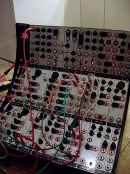
2.3 personal background
Is was always intrigued but also very impressed with anybody who could build something . I never
had a background in engineering or mechanics, but learned a lot over the years. Never have I felt
pressure to achieve a skill level or build something, this helped me a lot in developing the basic
skills and confident to design things today that are to a standard that is acceptable not only by
myself, but by other musicians and artists. Good work takes a lot of time and patience is a virtue.
I got into electronics when someone traded me a ‘bent’ drum machine for an old broken mixer and
it got me started with circuit bending my own noisemakers and toy keyboards. and using them live
and in the studio.
fig 2.3 my performance setup, including the ‘bent’
Casio SK1 (by Sabine Bolk. Breda 2008)
I learned to appreciate and enjoy building things for my work as a musician and sound designer.
Every year I see a progression in my work and am happy to now also see others enjoy my creations
and solutions. ere is still a lot to improve, but over the course of this research I have gotten a
much clearer view of the road I should take and what the next steps are to progress further in the
world of diy. From circuit bending and building an ‘atari punk console’ six years ago, I feel I have
already come a long way.
102.3.1 modification
e first period of circuit bending for me meant learning basic electronics and I improved my
soldering a bit and started to feel comfortable opening toys and working with electronic parts. For
my next project I had to choose between buying and or doing it myself, I needed to buy an electric
guitar. It shouldn’t be too expensive, it should be versatile and be good enough to practice and
record with. From the pickup to the shape of the guitar, I researched everything and constructed a
picture in my mind.
My budget was set around €300 , I couldn’t find a guitar that would suit all my needs for that
budget, but what if I bought an ever cheaper guitar and modify it?
For half my budget I bought a second hand korean make ‘Squier stratocaster’.
fig 2.4 fender squier stratocaster
I started playing it and learned it’s sound. I started researching everything I could find online on
guitar improvements. e Seymour Duncan website provided basic wiring diagrams for most
common configurations of a guitar. e squier as it was didn’t impress me much, but it’s potential
blew me away. For the next 6 months I started to work on the guitar, changing everything I could
and experimenting along the way. I learned how to browse the right forum for the right
information and plan ahead for every modification.
11I changed the tuners, the pickups and configuration, the body-plate and all the electronic parts.
And the best improvement of all, I properly shielded it with a Faraday cage.
fig 2.5 new and modified electronics
e results were good, the guitar was silent, stayed in tune, had a great sustain, pickup settings from
a creamy sounding neck pickup to a loud humbucker bridge pickup and it had a useful single tone-
knob, capable of shelving treble or bass off the signal.
fig 2.5 my main guitar, I still play today
I couldn’t be more satisfied and I’ve spent almost the same I would on a second hand guitar of
similar quality. An additional bonus to the hours of work I’ve put in, is that I now know how it is
wired and it is much easier to repair or further modify in the future.
122.3.2 kits and patches
All my circuit bending and work on my guitar was done by ear, I used internet references and
simple drawings as guidelines and just kept experimenting till things worked.
Doing that for a few years gave me a lot of basic knowledge on how these circuits work and how to
look at them.
Last year I redid a lot of soldering and improved my guitar and some of my circuit bent projects to
extend their life and use.
Besides circuit bending I was doing simple noisemaker kits (for example the ‘wacky sound
generator’ by http://musicfromouterspace.com) and programming a lot of patches circuits
on my computer in among other soware, max/msp. (http://cycling74.com)
fig 2.6 A patch I wrote for our Mayakovsky performances, the patch
generates video while transforming a live recording of us reading
Mayakovsky’s poetry and improvised clarinet.
http://www.youtube.com/watch?v=R5bnJu18BGs
Programming synths and patches and building kits opened my mind to new ways of thinking about
technology, over the years I went from using different types of gear to opening a lot of them up and
researching how things work.
“Create your own situation, that you know the ins and outs of” Make magazine
Learning more about the technology I was using not only improved my skills in the construction
and design of diy products, but it also improved the way I used the equipment in my studio.
132.3.3 circuits
My circuit bending has evolved and I focus more on interface design and artwork. I’m started to
learn electronics and am building very simple circuits from scratch using perfboard and veroboard
instead of pre made printed circuit boards.
fig 2.7 The Sammichsid synthesizer nearly completed without it’s
enclosure, a straightforward ‘paint by numbers’ type project that required
nothing but patience, precise and accurate work.
( http://www.midibox.org/dokuwiki/doku.php?id=sammichsid )
Every successful build motivates me and helps me improve the next. You advance a lot of skills
while working on circuits, soldering and reading schematics being the obvious, but there is also
logics, efficiency, measuring, planning and research involved that will benefit me as an overall
engineer.
Compared to the work I can do within a soware environment, building up skills in hardware
design sometimes feel like baby steps, but I noticed an overall understanding of sound and the way
musicians and artists interface with sound comes from working and experimenting in both
soware and hardware.
142.3.4 soware design
I spent a large deal of my education and internship working with soware and creating soware
solutions for a performance and an installation. I was lucky to be part of a project where we built
our own multitouch controller the size of a large TV. e project forced me into new directions,
such as modifying a webcam for infrared viewing and writing soware solutions to detect
movement on the multitouch and eventually control music soware with it. (I spent the first
three months of 2010 as an intern working in a team for Looplala and Born
Digital to construct the multitouch controller and it’s software)
fig 2.8 The multitouch interface running test software
in max for live.
fig 2.9 Software prototype in Jitter for tracking
fingers on the multitouch table.
152.4 So, what’s possible as a diy sound designer?
In both so and hardware design I am following a similar learning curve and every step is similar in
both situations, but require different skills and methods. Where in programming one relies very
much on theoretical knowledge of the material, in electronics one relies more on the laws of
electronics. In both worlds, the more you advance on the ladder, the more sensitive your work
becomes to error.
Circuit bending and creating presets can both result in unpleasant noise, and in the worst case
scenario, your toy will burn out or you’ll have a bad sound. Anyway, both can be seen as
experimentation and part of an important learning curve. When it comes to repair and writing
soware, there is less room to experiment and the goal of your work becomes more and more clear.
In the final stages you are most likely no longer working for your own benefits, but designing and
building for other users. Interface design, bug free soware and clean and professional work
become more important than the actual sonic exploration.
hardware: soware:
1. circuit bending 1. creating presets
2. modification 2.using and modifying soware
3. kits and repair 3.writing patches in open source soware
4. building and combining simple circuits environments
5. complete design of an electronic device 4.writing (open source) soware environments
ese two rows represent the progression I feel I can make as a diy sound designer in both hard-
and soware design.
I want to give two examples, the Midibox community and Rob Hordijk Designs, of a successful
completion of the above described progress.
http://www.midibox.org/
Midibox is a open source community designing and building synthesizers and midi controllers,
building on early experiments by orsten Klose, the community now delivers about 16 separate
modules, among them micro-controllers, sound modules, midi I/O modules and some users
provide full kits, where a selection of modules are pre arranged and offered with matching
enclosure and hardware. e soware is an open source and the community contributes to it’s
development at a speed exceeding for example the Korg kaosspad’s soware, which has only seen a
single, unfinished upgrade.
16e midibox community is also partly responsible for a lot of the exploration of the famous
commodore 64 sound chip, the SID. I’ve built a sammichsid, which is a midibox synthesizer based
around a SID module with two SID chips. It gives me full access to the chips sound capabilities
and gives me midi and audio in and output on a studio quality level. e kit I bought came with
everything I needed and the process of building it was easy and well supported by the designer on
the midibox forum.
fig 2.10 The sammichsid synthesizer under construction.
fig 2.11 The sammichsid synthesizer, a powerful and
productive part of my studio.
is is the first thing I built where I truly felt, I couldn’t have bought anything that would’ve made
me more content. I still use it a lot and am exploring the soware editing capabilities, making it an
even more powerful synthesizer.
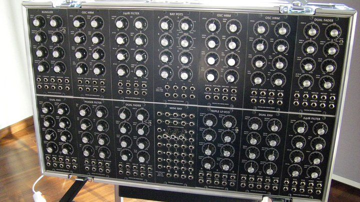
17In my research I visited Rob Hordijk to talk about diy and look at his recent work. He is a designer
and artist who worked extensively in the soware world, but is currently designing a range of
synthesizer modules that truly amazed me. e synthesizer modules are bigger than the common
Eurorack size for synthesizer modules, the knobs were very big and thus very musical. And the
layouts of all the modules had a symmetry in it that made the collection of them together look
calm and inviting.
fig 2.12 The layout for the oscillator out the range of synth modules by
Rob Hordijk. The simplicity and symmetry in the layout can be found in
all modules and is an incredible competitive feature when constructing
larger modular systems.
18fig 2.13 Complete modular system of Rob Hordijk design modules in a customized flightcase.
Design at this level is where I feel you are capable of building your sounds and tools completely
from the way up. A collection of useful modules with an enough connectivity and control to give
you a career long sonic palette.
I believe he serves as a true example in the field of DIY music technology and am very inspired.
A good read for any sound designer are his synthesis workshops:
http://rhordijk.home.xs4all.nl/G2Pages/index.htm
More details information on his synthesizer modules can be found at:
http://wiki.muffwiggler.com/wiki/Rob_Hordijk_Designs
193 From modification to design
3.1 circuit bending
My first encounter with diy electronics was by being exposed to the realtime hacking of a small
drum machine. e name ‘circuit bending’ sounded very intriguing.
Circuit bending is a term coined by Reed Ghazala and many other sound artists in the past 50
years. (Ghazala 2004) e Wikipedia entry defines it as:
“the creative customization of the circuits within electronic devices such as
low voltage, battery-powered guitar effects, children's toys and small digital
synthesizers to create new musical or visual instruments and sound generators.”
I went home and destroyed a lot of sound toys and keyboards. Although not many useful results,
musically nor artistically came from this short period of experimentation. I did gain an enormous
boost in creativity and made a lot of headway on the path of trial and error, working with different
electronic parts, circuit boards with nothing but your ears and ideas is the most inspiring of all
activities that relate to my creations. And the confidence and basic engineering skills and cras
obtained along the way helped me in every project up until now.
Circuit bending is a form of hardware modification and online a lot of toys and particular ‘bends’
have been popularized and are considered and used as instruments in almost every possible
scenario. From movie soundtracks [1] to sample libraries, to performance situations, the Casio
SK1 is a machine that has been hacked and modified in numerous ways and can be seen online in
all sorts of housings even with expanded interfaces resembling modular synth panels.
fig 3.1 Casio SK1 circuit bended into a modular synth.
By Peter Edwards of http://casperelectronics.com
[1] A circuit bent casio SK1 and other obscure toys and children keyboards were
used by musician Michael Andrews to compose the score for the 2005 movie ‘Me,
You and Everyone we know’
20e Texas Instruments ‘Speak and Spell’ circuit and the Furby are among many other famous ‘bent’
toys notable to mention.
fig 3.2 Circuit bended furby by OrminFactory
Circuit bending is no different from modification or even short circuiting and damaging circuits by
chance, the more theory is applied the more it can be considered modification or even electronic
redesign of a circuit. Circuit bending is, however, more than just the act of short circuiting, it is a
community around a form of hardware modification that is in many aspects close related to the
hacker culture.
“The hacker cyberculture .. it’s disaffiliation from a domestic parent culture
is often manifest in activities that answer, directly or indirectly, to the
legitimate needs of industrial R&D.” Kevin Mitnick, quoted in Strange Weather:
culture, science and technology in the age of limits (Ross 1991)
And within this community circuit bending takes on larger forms and connects various art forms
and aesthetics, making it a powerful statement and source of new art and music, and a to many
artists open and new way to look at being creative. Also all my circuit bending had an impact on
my lifestyle outside of music technology.
rough circuit bending I became more and more aware of recycling and I started to look different
at garbage and disposable or broken objects. One man’s trash is another man’s treasure. It certainly
is in circuit bending. I enjoy visiting thri stores and second hand markets, not only hoping to find
something useful, but also to be amazed at the materials, parts and beautiful things you can buy
today. A lot of people are throwing away perfectly usable stuff, it can save you a lot of money and
buying something already used forces you to work with pre designed interfaces or parts, which in a
way forces you to use ingenuity and be creative.
213.2 modification
From replacing pots and parts in your equipment to replacing strings, every musician and engineer
encounters the need to modify tools or instruments. Reasons can be improvement of sound,
special effects and or searching for new sounds. To be confident and do modifications to a circuit
without lowering it’s original quality requires research into the existing circuit and the intended
modifications.
e internet is a fantastic resource for such information, because modifications on many popular
circuits and instruments are well documented and can redirect you to the required schematics,
parts and their respected data-sheets to do a tested and oen paint by number approach to a
modification. is last metaphor also shows you clearly the difference between circuit bending and
modification, the last being a calculated procedure with a desired result in mind. While circuit
bending is oen encountered by chance and working directly on active circuits, modifying them
with whatever parts are available and judging their effect instead.
3.3 effect pedals
Building kits and circuit bending improved my practical skills, but did not give me enough
theoretical knowledge to actually design and build my own circuits and devices. e desire to build
my own things has grown over the years and I want to be able to build and design devices and
instruments that would also be useful for someone else and make devices that are original and as
useful as commercially available products. To get there I must start building slightly more complex
devices and learn to work with metal and circuits and schematics.
A world I already encountered in my endeavors with circuit bending was that of effect pedals, or
so-called stomp boxes. Not only limited to guitar players, I have encountered effect pedals in many
situations, including studio recordings, experimental performances and
almost every band I have seen on a stage.
fig 3.3 multiple pedalboards combined and
interconnected.
223.3.1 history
e world of effect pedals started when Jimi Hendrix and other guitarists in the sixties started
using foot switchable circuits on stage to further shape the sound or boost the amplitude of their
amplifiers. Roger Mayer had already constructed so-called fuzz boxes for Jimmy Page and Jeff Beck
when he met Jimi Hendrix. e Octavia effect (an overdrive pedal, which adds a sub-octave to the
signal grabbed Jimi Hendrix attention and the work the two have done in the years that followed
shaped the way we look at and use guitar effects. (Hodgson 2011)
From string gauges to the tuning of the guitars to the effects and combination of guitars and amps,
Mayer was as much responsible for the sound as Jimi Hendrix himself. A great example of the
benefit a musician can have from an engineer.
fig 3.4 Jimi Hendrix playing his wah pedal.
233.3.2 fuzz
Early effects were based on dynamics and used to further boost amplifiers on stage. is led to
distortions and overdrive sounds and this led to the evolution within effect pedals from simple
boosters to a rich and exotic catalogue of distortion, fuzz and overdrive circuits. Cloned, modified
and circuit bent over the years and recently these circuits and their evolutions and clones have been
extremely well documented and explored in internet communities. (freestompboxes.com)
fig 3.5 A collection of fuzztone pedals. Picture by Germanium 1999. http://
www.flickr.com/photos/germanium/866689808/
“Used to record the single ‘(I can’t get no) satisfaction’ by the Rolling
Stones, the FZ-1
was the first distortion effect (Fuzztone) on a hit record.”
- Fuzz Guide, The science, history, artists, methods and devices of the greatest
effect in history of music: fuzz. by kubton.com
243.3.3 modulation
Apart from capturing amplifier sounds and artifacts from overdriving amplifiers in small stomp
boxes, the guitarists also wanted to use effects on stage that were previously only available in
recording sessions. R.G. Keen classifies effect pedals into 5 main categories (Keen 2000):
-Amplitude base
-Waveform distortion
-Filter/Frequency response
-Time delay
-Miscellaneous effects such as harmonic generation and the talk box.
Every effect can be placed in one of the first four categories and every effect has it’s roots in either
an effect resulting from a playing technique, for example the use of the tremolo bar on a guitar for
vibrato, or an phenomenon resulting from equipment, unstable tape recorders speeds or the
overdriving of an amplifier. Since tape dominated the recording industry for over three decades, we
have a lot of modulation effects and delays based on tape recorders.
Today many great effect pedals are (digital) clones of those earlier devices. For example the recent
Boss re-20 pedal is a direct imitation of the roland re-201 space echo.
fig 3.6 + fig 3.7 The original Roland space echo tape unit and
the reissue digital effect pedal by boss.
25Robert Fripp was an early pioneer in the field of tape effects, he used two Revox tape recorders to
create long ambient drones and soundscapes with his guitar from the early sixties onwards.
fig 3.8 Robert Fripp pioneering his Frippertronics
by utilizing tape recorders as looping devices for
guitar improvisation.
In the seventies with the arrival of solid state bucket brigade delay technology ( a delay circuit using
IC based circuitry without any moving parts, like it’s tape predecessors ) came chorus, phasers,
flangers, vibrato and echo and delay units, still explored and combined into new effects today.
ose early designs were analog and had a lo fidelity now sought aer and labelled warmth.
Quickly aer the development of the analog bucket brigade delay came the first DSP (digital sound
processing) effects, including digital delays and effects capable of carbon copies of a signal with a
much higher quality, because of a lacking in added so called warmth, both analog and digital
designs are still equally popular and produced today.
3.3.4 experimentation
In order to built something original I need to start building prototypes and get away from cloning
and building existing circuits. New effects can be found by combining not only various existing
designs , but also using technologies outside the music industry. I have had great success using a
Wiimote hidden inside a ball during a performance, triggering sound effects and samples during
the piece. It required practical and technical solutions that fitted the needs of the piece and the
performers and by combining two very different things I came to a new use of the wiimote and a
way to make it invisible on stage. Here’s a simple graphical representation I made to present the
original idea to the theater group:
----->
26During my time as an intern with Jos Zwaanenburg, I explored the possibilities of electronic effects
by adding a laptop to each of the eight acoustic instruments in an ensemble and by contact mic and
a max patch, players had realtime effects reacting to their performances dynamics and pitch.
Under supervision of Jos Zwaanenburg I learned new strategies to manipulating an acoustic
instrument, by better analyzing the instrument and the performance, extracting useful data and
mapping them to interesting effect. It was an intense time, where I spent long hours programming
and testing out ideas and patches with the eight musicians. It was very rewarding to watch the piece
unfold, we played it for a small audience at the conservatory of Amsterdam late 2009.
fig 3.9 The max patch I wrote for each of the eight performers of the piece
“Octet ’61” at the Conservatory in Amsterdam 2009.
273.4 Sound Generators
In addition to effects and ways to manipulate sound, it is easy to build your own sound generators.
Oscillator circuits, tape devices and full featured synthesizers come in all shapes and forms. e
eurorack family of synthesizers allows users to set up a modular system by adding small building
blocks in the form of single rack space panels containing an oscillator, LFO, pattern generator,
filter, or any other sound shaping circuit. A variety of big and small brands are available in the
eurorack, as well as numerous smaller companies, a lot of pedal builders branch out into the
modular synthesizer world (http://www.umop.com/tm7.htm), and Moog has great success with
their Moogerfooger range of effect pedals. Like those mentioned Moogerfoogers a lot of pedals
provide CV input so you can connect them to a modular system.
( http://www.moogmusic.com/products/Moogerfoogers )
I have hacked simple sound devices into more usable sound generators, for example the buddha
blender, it contains small chant boxes I mail ordered, each one has a button to switch through 5
loops, a volume pot and a small speaker. I removed the speaker, installed a 1/4” output jack and
added a pitch pot to the circuit, I boxed several into a big wooden enclosure and used it in a few
performances. I am working on a second version of the buddha blender, where I’ll have two circuits
in a small enclosure with a single output and a pot to blend between the two voices.
fig 3.10 The buddhablender (to the left) with a
simple mixer and a kaosspad as a performance setup.
I would like to improve my knowledge on actual sound generating chips and circuits and build
sound circuits completely from the ground up, but I have enough to work with at the moment to
explore and learn from. It is a long way up the learning curve, but over the past six months I have
experienced serious progress and a confidence that will take me further with my work.
I’d like to continue working with a circuit bending mentality to experiment more and get a better
idea of what will work in my future designs. You learn an incredible amount when you have to built
a circuit into an unconventional enclosure as you do with a lot of circuit bending, when you have
to add knobs and switches to a furry caterpillar shaped toy .
28fig 3.11 + 3.12 + 3.13 I built a MFOS ‘wsg’ synthesizer kit inside an old Sega
Master System II game console case. http://musicfromouterspace.com
293.5 soware solutions
Working with soware and programming tools, sound generators and effects in max/msp and the
Nord modular advanced my sound design skills in areas that overlap with the design and building
of hardware tools. I benefit from this experience in two interesting ways.
3.5.1 soware prototypes
I can prototype and test my feature hardware designs on my computer, estimate the effects of
modifications and achieve new ideas. e computer is a clean, fast and very straightforward way of
experimenting compared to a breadboard. e logic approach of a max patch has similarities to a
circuit, but is less sensitive to outside factors, it proves to me a very stable and rewarding place to
explore sound design. e Nord G2 modular is another fast and good way to explore sound. It has
most of the building blocks required to rebuilt a lot of circuits and ideas and is much easier to
control, modify and save.
fig 3.14 Experimenting with ring modulation with the Nord G2 engine.
303.5.2 soware controllers
Besides the keyboard we can use percussion and wind controllers, guitar simulations, the voice and
sensors. Because of small innovations and in a lot of cases diy (monome) the midi keyboard has
evolved into matrix controllers(launchpad, akai apc), turntable(ms pinky, traktor), motion tracking
and video interaction (jitter), joysticks, wiimotes and many other ‘hacked’ controllers. ( http://
web.media.mit.edu/~joep/SpectrumWeb/SpectrumX.html)
And what a user is capable of doing with such tools is up to the soware designer and the mapping
between a device and the soware. is mapping is an ongoing learning experience. My
‘funambulism’ patch is a granular delay system for processing audio over 4 speakers.
fig 3.15 I use max to map the joystick
movements to the distribution of the grains
over the four speakers and I use max/msp to
map the novation launchpad as a color coded
matrix to what delays are active.
I wrote the patches and tested it during a residency at STEIM with the Live Cinema ensemble.
And kept improving it aer every performance and last year used it in a new ensemble. Aer a few
periods of improving and practicing I now have a very powerful, unique performance tool, which is
stable and easy to play with.
fig 3.16 My performance setup for the Orpheus2010 Live
Cinema performance.
313.5.3 hybrids
Another aspect of soware programming that attracts me is connecting both worlds, the world of
hardware, sensors, gestures and controllers and the world inside the box.
Effect pedals with Arduino, soware controlled circuit bending, a lot of experimenting has begun
in the overlap between the various disciplines, but there is a lot more to invent and build.
Sparkfun electronics is a company that has a lot of tutorials and resources and you can buy Arduino
and related materials and components to build all sorts of cross-media installations.
fig 3.17 We want to use electronics to make art projects, gadgets, and robots.
We live, eat, and breathe this stuff! The SparkFun crew works in various
departments such as engineering, marketing, production, shipping, and keg
replenishment, all united in one common goal - Sharing Ingenuity. (from their
website http://sparkfun.com)
e Arduino platform is an example of a cheap and easy way to connect the soware and hardware
worlds together and from there any modern laptop is capable of connecting all kinds of controllers,
sensors and capture sound and images. Finding strange combinations and creating simple and
useable interfaces for use in a performance or studio environment is an ongoing part of my work.
Besides creating new controllers and experimenting with micro-controllers, we can already create
new tools by using existing technology in a new way. A laptop equipped with a little bit of soware
is capable of analyzing live video and audio data and mapping joysticks, or other control surfaces to
musical gestures.
324. Applied tools and techniques
4.1 sound design
A large part of the work I do is related to sound design. e purpose of these designs is either to
create new sounds or manipulate existing sounds and instruments to do so. Sound design is a wide
term and this paper relates to the audio design and sound art side of the term, not the traditional ‘
composing sounds for film ‘ . I believe a good knowledge of sounds and it’s behavior is a large
advantage in my work. To be able to judge if a sound is useful or worth further developing and also
to understand what you are trying to reach with a design and when to consider it done.
4.2 signal theory
As in synthesis, a good knowledge of signal theory is required in the design of both circuits and
audio soware. e oscilloscope proves not only a problem solver, but also a new approach and
more exact way to literally look at sound. A lot of effects are harsh and modify a signal in ways that
small changes in a design are undistinctable by ear. Looking at a signal on a scope or in the form of
data or a simple measurement with multimeter will sometimes tell you something, your ears can’t.
Although it is good practice to measure and be exact in your work and always strive for perfection,
a lot of great designs and sounds are achieved by working by ear and as with everything related to
sound design, it is not an exact science, but an art form.
“Rule #17: If it sounds good and doesn’t smoke, don’t worry if you don’t
understand it.” Hardware Hacking - Nicolas Collins
fig 4.1 My soldering, testing and construction workspace.
334.3 electronic engineering
All art requires cras and cras are skills that are perfected by both practical experience and
learning the rules and procedures. Electronic engineering is a large field and there are many starting
points in studying it, I pick up knowledge as I go along each project and try to pick up something
new every time.
fig 4.2 From breadboard prototype (right)
to perfboard (left)
I also read up on articles related to my work, but in another context, hobby websites for electronic
engineering in non musical fields, model trains for example, are less biased towards sound and can
oen give you fresh ideas and techniques overlooked when everyone is focussed on the same
methods.
4.4 soldering
Good soldering skills are a necessity and is developed by trial and error. e better the solder joints,
the less time you’ll spend debugging your circuits and the better your succesrate, the more
confident you get and so forth.
fig 4.3 Finished perfboard circuit.
344.5 programming
Programming is in a large way identical to creating circuits, we are in both situations limited to
certain mathematical logic and laws of physics to make something work and behave in a desired
fashion. And both have an almost identical learning curve as I illustrated on page 16 .
fig 4.4 The Nord G2 is a powerful modular synthesizer and rich featured studio tool,
making it a perfect environment to test and prototype new sounds and ideas.
fig 4.5 Parts of my ‘Funambulism’ Max software described on page 31.
354.6 interface design
In the age of the interface, it is of an upmost importance in every design, soware or hardware, to
build and create a useful and inviting interface, successful commercial products are oen praised
for their interface.
fig 4.6 The Korg Kaosspad 3 is an XY touchpad effects
processor, sampler and midi controller. http://korg.com
Korg have their Kaoss Pads, which are a way of taking sounds into the domain of
muscular control. If you have a few Kaoss Pads in line, like I do, you can
really start playing with sound itself, with the physical character of the
sound. The pads are very intuitive, anyone can learn to use them in a second.
It's immediately obvious what you do, and it immediately takes you into a
completely different place, because when working with computers you normally
don't use your muscles in that way.
- Brian Eno quoted in Sound on Sound October 2005
Besides making a device easier to work with, an interface dictates a users performance and a better
interface usually leads to better use. Also it can lead to design problems, which provide a basic idea
and oen healthy limitations for the artwork. In a well designed product, both art and interface
design are thus complementing each other.
364.7 artwork
Artwork is closely related to interface design and the two influence each other greatly. Art is a part
of design that is to me as important and challenging as the circuitry of a design. Even a max patch
is more inviting if it has a background tint, some color, maybe small pictures. In stomp boxes there
is not a lot of space, nor variety in the way a design is laid out. One or two foot switches, one to
several potentiometers and sometimes a few switches. Almost every diy stomp box fits this
description and sizes do not vary that much, from a few industry standard sizes.
Still there are designs out there every day that surprise me and with some the art is almost as
desirable as the purpose of the effect itself.
I use hands-on processes, mixed media, from screen printing, to self-developed stamping,
painting, and graphic processes. The result of my DIY approach to building instrument
effects makes for a product with a more unique, less "factory" look...an appearance of
being hand-built or crafted, which (hopefully) adds to the appeal and pride in ownership.
Many are one-of-a-kind pedals, with brush-strokes.
(Tom Dalton, FuzzHugger effects, the entire interview can be found in Appendix B)
Also the artwork can give your designs a personal character or help sell them, everyone wants their
instruments to look good!
fig 4.7 A pedal painted by artist Pat Corrigan for
fuzzhugger effects. http://fuzzhugger.com
375 Evaluation
5.1 results
I want to specifically examine a selection of the products I made during the past 6 months of
researching this subject. Here are some picture build logs of some of the things I built, followed by
my personal review and some by musicians I worked with and who have used these devices.
5.1.1 circuit bending
fig 5.1 Blue toy wheel added an on/off switch, led and 4 body-
contact points for controlling the clock speed and glitches.
I circuit bended this steering wheel toy, by adding 4 contact points to the circuit and adding an on/
off switch with LED. e toy was old and the circuit and components fragile and it stopped
working aer a few days of use. Still it is aesthetically a very pleasing result and for a switch, LED
and 4 metal pins, no loss at all. It is a fine example of the oen short lives a circuit bended toy can
have, but how simple, fun and pretty the results can be.
38fig 5.2 Vtech Teddy The Bear toy painted and I added a ‘loop’ and
‘glitch’ switch.
A V-tech talking teddy, I saw getting ‘bent’ during the first circuit bending workshop I did in 2008.
I found a similar teddy and did an homage. ere’s only a loop and glitch switch, otherwise it still
behaves normally.
fig 5.3 Bert and Ernie toy-phone, light sensitive right
eye glitches and alters the speed of the sounds.
I always wanted to experiment with photosensitive cels, or so called ‘light dependent resistors’
LDR. Here I glued one into the phone’s right eyes and placed in place of the resistor controlling
the clock speed of the circuit. It’s a lot of fun and gives me a lot of ideas. One being vectrols, which
I’ve used in the modification of an Electro-Harmonix Small Clone pedal, described later.
39fig 5.4 The Casio SK1 sampling keyboard, bended according to Reed
Ghazala’s ‘Aleatron’ layout. (Ghazala 2005)
e famous Casio SK1 sampler, I did everything I could to this one. It is a very early project of
mine and although it has a very bad solder job and almost falls apart, it got me started and I used it
enormously in my work and performances. I have more SK1’s which I use as regular samplers and I
still want to work on one with an external controller for it’s numerous switches. Even bridging it to
max would be a possible and that proves why the sk1 is a classic machine for circuit bending, there
is so much to bend and add to the already large sonic palette, also due to the almost ancient, but
characteristic sampling capabilities.
fig 5.5 Realistic Rap-Master, painted and added feedback loop, glitch and
noise controls. Also combined two different manufactured rap masters and a
boss pedal to get the knobs and switches in a Jamaican ‘dub’ color scheme.
Here is another casio from the eighties, the rap-man, or in this version the realistic rap-master. It is
a not very musical keyboard by casio, with a lot of generic early rap and disco loops, the one thing
that stands out is a microphone input and a 5 way switch to pitch shi the incoming signal. I
created an internal feedback loop through the pitch shier, creating dub style effects heard on early
king tubby production. I took apart two rap-man keyboards to collect enough parts for the reggae
layout and color schemes. I am very proud of the way this looks.
405.1.2 modification
e small clone is a chorus pedal made by Electro-Harmonix, it is a simple unit, with a few
drawbacks. ere is a control for the rate and a switch for the depth. Now the rate range is just fine,
but the switch goes from very gentle to very deep and thus a seasickness effect. I knew there were a
lot of possible modifications and really wanted to be able to get more out of this pedal.
fig 5.6 The Electro-Harmocix Small Clone chorus, with tremolo and depth pots.
I found several reports of successful modifications and decided on what I wanted, I wanted the
depth switch replaced by a pot, giving me a large range between subtle and seasickness. I also found
a very simple and logical tremolo mod, by connecting a so called vectrol (LED into an LDR) to the
LFO and using the resistance on the output of the pedal, by adding a pot to the resistance, you can
vary how much the vectrol influences the output, thus how deep the tremolo goes. e tremolo is
in synch with the chorus, because they share a similar LFO.
fig 5.7 + 5.8 A DIY vectrol.
41e small clone is a welcome addition to my pedalboard and it was an easy and fun build without
any difficulties, the vectrol part gave me a lot of new ideas to work with.
fig 5.9 The modified circuitry of the small clone.
5.1.3 Effect Pedals
fig 5.10 Tim Escobedo’s Too Many Knobs fuzz, is an IC
based fuzz and distortion circuit and the graphics were
done by Michael Polane.
I enjoyed building the pedal and having someone else do the artwork. e results are far beyond
my capabilities as a graphic artist. And I am happy to have found some enthusiastic artists to work
with in the future.
42fig 5.11 The hysteresis pedal, notice how I made a
drilling mistake and switched around the stomp switch
and LED. It’s not a big mistake and it gives the pedal
a nice ‘face’, so I left it this way.
is is the first effect pedal I built, I took two simple schematics, one of a 555 timer oscillator and a
tone control and put them both on breadboard. I tried different parts, exchanged parts and just
went with the flow, until it sounded just right to me.
fig 5.12 Inside the pedal
I used a small piece of perfboard and soldered my results to it. It works and although it is a very
simple circuit and nothing original, it showed me I didn’t have to rely on other people’s layouts and
circuit-boards to build my things, but that it did require a lot more preparation and knowledge.
Compared to the echobase (described on the next page), both pedals are equal in difficulty to
produce, a good layout and clear interface design is really half the work.
43fig 5.11 The echobase is an analog voiced delay circuit
with modulation and a digital switching circuit giving
you a lot of useful functions and options for further
modification. http://musicpcb.com/pcbs/echo-base-delay/
e echobase is a very good analog delay with modulation. ere is a lot of features and
modification information available and I am building two more with different modifications to
experiment with different versions of the echobase. e circuit is designed by Ian of musicpcb.com
and further developed and modified to it’s current form by members of the diystompboxes forum.
Today it is available as a pcb and all the information you need to customize it. Here is the original
thread on the echobase:
http://www.diystompboxes.com/smfforum/index.php?topic=60662.0
is shows the power of a good forum in the 21st century, the ability to share your initial idea and
revise and perfect it with the help of hundreds of peers. Leading to, in this case a delay pedal, that
can be compared to a lot of commercially produced delays. with the same set of features.
An advantage of working with a pcb is that I had the most difficult part of the pedal already done
for me, the design of the actual circuit. Constructing the case, collecting and soldering the parts
and doing the artwork is where I had to be cost effective, original and creative. e result is great
and I am very satisfied with the way it looks and functions. If I didn’t build it, I would’ve bought it.
44Recently I got my first request for a pedal, the instructions for what it should do were clear and I
got some hints for the artwork. I used stencil techniques and a lot of layers of paint to achieve this
effects, it turned out beautiful, the pedal looks worn and damaged in a good way and technically it
does exactly what was requested. I am happy I am able build something like this for someone.
fig 5.13 A customized boost pedal, built on request.
Looking back over the past six months I learned that planning and endurance are more important
to a good product than money or skills. You can do it yourself and you can learn techniques by
reading up on them, talking to others and keeping an open mind to all sorts of arts and cras,
maybe not directly related to your own work. I am amazed how good my current paint-jobs look,
compared to a year ago. Also I feel more at ease with trying new things.
fig 5.14 A second echobase pedal I am building.
I am less scared to fail, very positive about my work and the work of those that inspire me and it
moves me forward.
45You can also read