Optimization design of electric field potential for high-speed EMU high voltage box - IOPscience
←
→
Page content transcription
If your browser does not render page correctly, please read the page content below

Journal of Physics: Conference Series

PAPER • OPEN ACCESS

Optimization design of electric field potential for high-speed EMU high
voltage box
To cite this article: Ming Zhao 2021 J. Phys.: Conf. Ser. 1865 022065

View the article online for updates and enhancements.

 This content was downloaded from IP address 46.4.80.155 on 01/08/2021 at 13:14
2021 International Conference on Advances in Optics and Computational Sciences IOP Publishing
Journal of Physics: Conference Series 1865 (2021) 022065 doi:10.1088/1742-6596/1865/2/022065

Optimization design of electric field potential for high-speed
EMU high voltage box

 Ming Zhao
 CRRC Changchun rail car Co., Ltd., Changchun 130062, China

 gybzm@sohu.com

 Abstract. Establish the three-dimensional model of high-voltage box and its internal
 main electrical equipment of EMU. Under the lightning overvoltage condition, through
 modeling and analyzing the electric field potential distribution of high-voltage
 components of EMU, understand the insulation weak links of high-voltage components,
 optimize the insulation gap of high-voltage components, local structure of components
 and system layout, and systematically master the layout design of high-voltage
 equipment of EMU method. The research results show that under the lightning
 overvoltage condition, the areas with higher electric field strength are mainly
 concentrated in the inlet port of the cable and the outlet port of the circuit breaker, the
 maximum electric field intensity is concentrated near the electrode of the
 electromagnetic voltage transformer, and the maximum field strength in the high
 voltage box is 21.5kv/cm, which meets the air breakdown standard, has certain safety
 margin and meets the insulation requirements.

 Keywords: EMU, high voltage, lightning, electric field, potential.

1. Introduction.
High voltage system on the roof of high-speed train is the core of train energy supply, and its electrical
safety is directly related to the safe and stable operation of high-speed train. With the improvement of
EMU operation speed, the over-voltage impact of EMU occurs frequently, which results in insulation
breakdown and insulation aging acceleration of on-board electrical equipment, resulting in a sharp
decline in insulation performance [2-3]. As the high-voltage system is located outside the roof, the high-
voltage insulation parts are easy to be eroded by wind, sand, salt fog and other erosion, which further
reduces the insulation performance of high-voltage system components, resulting in insulator flashover
along the surface, short-circuit of catenary to vehicle body, tripping of isolating switch of traction
substation, and even posing a threat to the safety of passengers [4-5]. The insulation flashover faults of
high-voltage components on the roof of high-speed trains have occurred many times on typical high-
speed railway lines such as Beijing Tianjin line and Zhengzhou-Xi'an line, resulting in many trains being
delayed or even stopped.
 To this end, the high-voltage system of EMU is placed in the high-voltage box from the roof outdoor,
so as to reduce the impact of the environment on the high-voltage system, which is gradually paid
attention by major engine manufacturers [6-7]. However, due to the limited space of the high-voltage
box, it is necessary to integrate the voltage transformer, current transformer, circuit breaker,
 Content from this work may be used under the terms of the Creative Commons Attribution 3.0 licence. Any further distribution
 of this work must maintain attribution to the author(s) and the title of the work, journal citation and DOI.
Published under licence by IOP Publishing Ltd 1
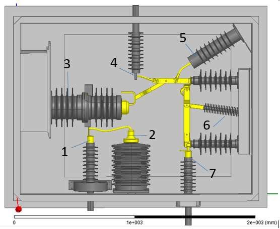
2021 International Conference on Advances in Optics and Computational Sciences IOP Publishing
Journal of Physics: Conference Series 1865 (2021) 022065 doi:10.1088/1742-6596/1865/2/022065

disconnector, lightning arrester and other high-voltage equipment in the limited space, which puts
forward higher requirements for the insulation design of the high-voltage equipment in the high-voltage
box. Otherwise, the strong electric field will easily cause the discharge of the high-voltage end to the
ground and the high-voltage end to the low-voltage end, which will accelerate the aging of the high-
voltage components Cause insulation breakdown.
 Through the establishment of three-dimensional model of high-voltage box and its internal main
electrical equipment of EMU, this paper analyzes the internal electric field potential distribution of high-
voltage box when subjected to lightning strike, and understands the insulation weak link of high-voltage
components, which provides important theoretical basis for the design and normal operation of high-
voltage box.

2. Theoretical analysis.

2.1. layout of high pressure box.
The three-dimensional layout of the high-voltage equipment box of EMU is shown in Figure 1. It can
be seen from the figure that the main electrical components in the high-voltage box mainly include the
inlet port, outlet port, voltage transformer, main circuit breaker, lightning arrester, high-voltage
disconnector, cable, etc. Figure 1 also shows the incoming and outgoing lines in the high-voltage box.
After receiving current from the catenary, the pantograph enters the high-voltage box through high-
voltage cable and is divided into two circuits, one of which passes through the current transformer and
then the vacuum circuit breaker. At the same time, the resistance voltage transformer and
electromagnetic voltage transformer are used to monitor the network voltage, and the current
transformer monitors the network current; the other is connected to the isolating switch and
interconnected with other motor cars through cables. Under normal working conditions, the working
voltage of high-voltage equipment in high-voltage box is 25kV single-phase alternating current.

 Fig. 1 Structure diagram of high voltage box of EMU (top view)
 1-incoming port; 2-voltage transformer; 3-main circuit breaker;
 4-appear port 1; 5-arrester;
 6 - high voltage disconnector; 7 - presence of port 2

2.2. Standard lightning current.
Standard lightning current waveforms are specified in standard SAE ARP 5412, and current components
a and D are suitable for assessing indirect effects. In contrast, a has higher amplitude and action integral,
so the influence of current component A is greater, so the current component A is selected as the
experimental waveform. In the standard, the current waveform a is required to reach a peak value of 90%
within 3 μ s and a peak value within 6.9 μ s (± 20%) [8-10]. The time to half value should be 69 μ s (±

 2
2021 International Conference on Advances in Optics and Computational Sciences IOP Publishing
Journal of Physics: Conference Series 1865 (2021) 022065 doi:10.1088/1742-6596/1865/2/022065

30%). A few negative flashback parameters were combined with the a current waveform. At low altitude,
the environment represented by this kind of pulse appears most frequently. In our experiment, the scaled
waveform is used to reach the peak value within 6.9 μ s (± 20%). The time to half value should be 69 μ
s (± 30%). In order to facilitate quantitative analysis and engineering calculation, the lightning current
waveform is equivalent to a double exponential waveform. The standard waveform is shown in Figure
2, and its mathematical expression is as follows:
 ( ) = ( − ) (1)
 Where I0 is 218810a, α is 11354s-1 and β is 647265s-1.

 Fig. 2 Lightning current waveform

 Corresponding to the standard lightning wave; the lower limit of lightning full wave impulse
withstand voltage of roof insulator in TB / T 3077-2003 is 170 kV, and 180 kV voltage is selected as
the voltage under lightning overvoltage condition.

2.3. Analysis of electric field potential safety criterion.
In order to improve the safety performance of the high-voltage components in the high-voltage box, it
is necessary to make the high-voltage components in the high-voltage box operate safely and stably
under normal conditions and some extreme conditions. In the design, the initial field strength of corona
discharge is mainly referred to, and the lightning overvoltage condition is taken as the terminal condition.
 According to the structural layout of high-voltage box, the electric field environment of high-voltage
system is very complex. The inhomogeneous coefficient f of electric field is usually used to judge
slightly uneven electric field and extremely uneven electric field, uniform electric field F = 1; slightly
uneven electric field 1 < f < 2; extremely uneven electric field F > 4. However, because f > 1, the average
field strength in the gap is smaller than that in the uniform field gap. Therefore, the breakdown voltage
of the slightly inhomogeneous field gap is lower than that of the uniform field gap at the same gap
distance. The self sustained discharge condition is the starting condition of corona discharge. The corona
initial field strength under the extremely uneven electric field is slightly lower than the breakdown
electric field of air, and the stable corona cannot be allowed in the insulation system, so the corona
inception voltage becomes the basis of insulation design. Under the condition of extremely uneven
electric field, the gap discharge first refers to corona discharge, because the corona inception voltage of
the gap is slightly lower than the breakdown voltage UB. When the gap D approaches infinity, i.e. the
air gap distance is not considered, the initial breakdown field strength of air is 24.22 kV / cm. When the
gap distance is in the range of 1 ~ 10 cm, the breakdown strength EB is about 30 kV / cm.

 3
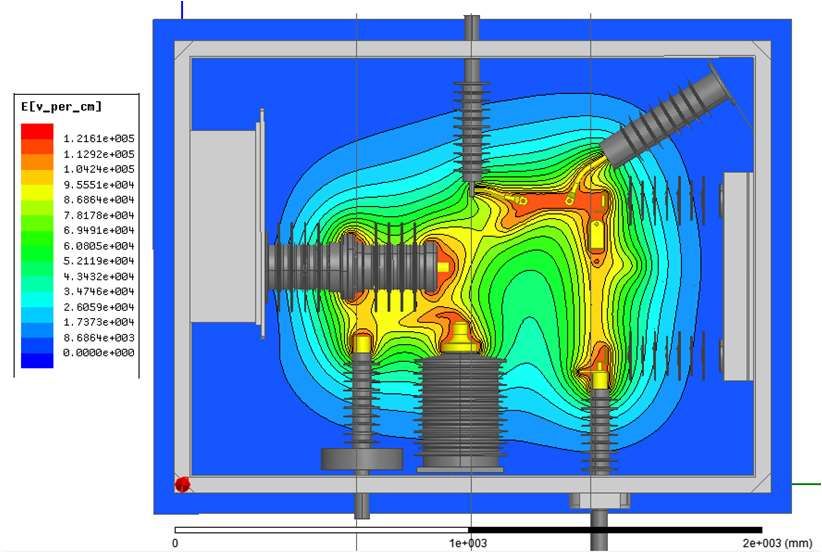
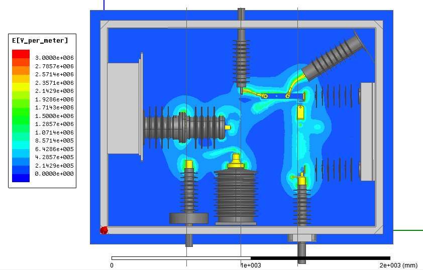
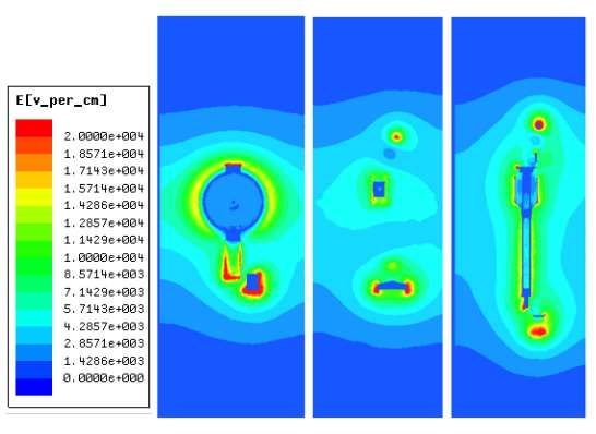
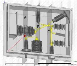
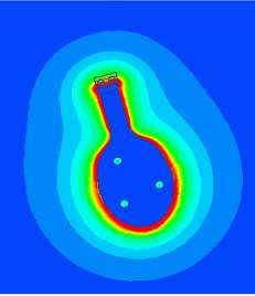
2021 International Conference on Advances in Optics and Computational Sciences IOP Publishing
Journal of Physics: Conference Series 1865 (2021) 022065 doi:10.1088/1742-6596/1865/2/022065

3. Simulation analysis.
The upper surface of busbar connecting arrester, outlet port 1 and disconnector is selected as horizontal
reference plane, vertical reference plane a of incoming port, vertical reference plane B of outlet port and
vertical reference plane C of outlet port II are selected as vertical reference plane. The schematic diagram
of reference plane selection is shown in Fig. 3.

 Fig. 3 Internal reference plan of high pressure box

 The distribution of field intensity in the high voltage box is analyzed under the lightning over-
voltage condition. Under the lightning over-voltage condition, the excitation parameter is set to
170 kV. The overall electric field potential distribution of the high voltage box is shown in the
figure.

 Fig. 4 Overall potential distribution of high voltage box

 Fig. 5 Electric field distribution of high voltage box

 4
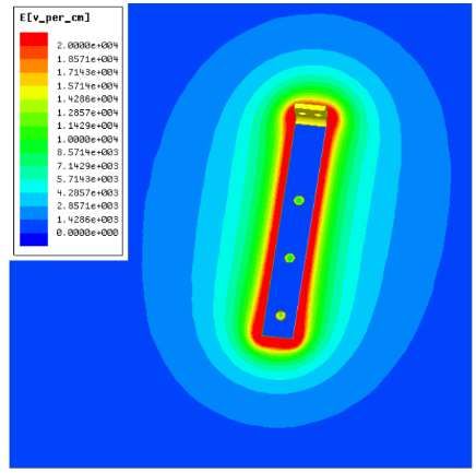
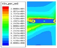
2021 International Conference on Advances in Optics and Computational Sciences IOP Publishing
Journal of Physics: Conference Series 1865 (2021) 022065 doi:10.1088/1742-6596/1865/2/022065

 Fig. 6 Electric field distribution of plane ABC (left main circuit breaker)

 According to the figure, in the case of lightning overvoltage, the area with higher electric field
strength is still mainly concentrated in the inlet port of bushing and the outlet port of circuit breaker, and
the maximum electric field intensity is concentrated at the inlet port. This area is mainly the insulation
between the cable core and the high-voltage box shell, and its main insulation is high-voltage cable
insulation, which can fully meet the needs of electrical safety.
 In addition, in the case of lightning overvoltage, the electric field distribution near the two busbars
between the main circuit breaker and the high-voltage disconnector in the high-voltage box is
investigated. The field strength near the busbar is shown in Fig. 7. The maximum values are 23.4kv/cm
and 24.5kv/cm respectively.

 Fig. 7 field strength distribution near busbar

 According to the simulation diagram of the high-voltage box, when the connecting busbar between
the main circuit breaker and the disconnector is subjected to lightning overvoltage, its field strength is
that it is far away from the corona, and the safety margin is small. In order to improve the electrical
safety in the high-voltage box, the local analysis model of the high-voltage components of the
connection bus bar is established.
 In order to improve the distribution of electric field strength near the bus bar, the connection bus bar
between the main circuit breaker and the disconnector is optimized, and the local field strength
distribution is studied by simulation analysis, so as to provide reference for the next optimization, and
then the electric field distribution of its weak links is further analyzed. Because the simulation analysis
object only involves the bus bar and high voltage box, the electric field distribution results are different
from the overall results. The problem to be explained through optimization is to take optimization
measures to reduce the electric field distribution nearby.
 Figure 8 shows the peak value of lightning strike voltage. After solving the simulation model
potential and electric field by finite element analysis software, the overall distribution of electric field
near the bus bar is obtained. It can be concluded from the figure that the maximum electric field strength
is 23.4 kV / cm. In order to avoid the local electric field distortion caused by it, and to reserve sufficient
safety margin, it is suggested to fillet the bus bar to avoid air corona discharge due to the nearby electric
field distortion when it is subjected to overvoltage. The right angle side of the bus bar shall be filleted
with 1 mm, 2 mm and 3 mm fillet respectively. The simulation results show that the maximum field
strength decreases to 23.1, 22.6 and 22.0 K respectively V / cm, but the optimization effect is limited.

 5
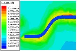
2021 International Conference on Advances in Optics and Computational Sciences IOP Publishing
Journal of Physics: Conference Series 1865 (2021) 022065 doi:10.1088/1742-6596/1865/2/022065

 Fig. 8 Distribution of electric field intensity near busbar and in the disk model

 Further, the shape of the bus bar is changed from rectangle to round cake, and then it is stretched and
rounded. On this basis, the field strength distribution is simulated and analyzed, as shown in Fig. 9. It
can be seen from the figure that the maximum electric field strength of the bus bar after similar round
cake treatment is 19.1kv/cm. Therefore, it can be seen that fillet treatment can improve the distribution
of electric field around the busbar and optimize the surrounding electric field Field environment,
increase the electrical safety margin, improve the electrical safety performance.

4. Summary
In this paper, through the establishment of three-dimensional model of high-voltage box and its internal
main electrical equipment of EMU, the electric field and potential of voltage transformer, main circuit
breaker, lightning arrester, high-voltage disconnector and other main electrical components and their
connecting metal parts in the high-voltage box subjected to lightning stroke are simulated and analyzed
to understand the weak insulation links of high-voltage components, That is, the bus bar between the
main circuit breaker and the disconnector is optimized, which provides an important theoretical basis
for the design of the high voltage box and its normal operation.

References
[1] Ma shengpan, Li Bing, Jia buchao, et al. Study on residual charge discharge of high voltage
 system on the roof of CRH2 EMU [J]. Rolling stock, 2018 (5): 9 ~ 11
[2] Deng Xuehui, Niu Detian, Liang Shulin. Study on the influence of grounding mode on Lightning
 Overvoltage of high speed EMU body [J]. Mechanical and electronic, 2018 (8): 17 ~ 20
[3] Gao Guoqiang, Liu Yaoyin, Wan Yusu. Research on surge overvoltage of high speed EMU
 pantograph lifting [J]. High voltage technology, 2016 (9): 2909 ~ 2915
[4] Wang fochi, Han Yong, Liu Hongyu, et al. Simulation study on erosion and wear of EMU roof
 insulator under wind and sand environment [J]. Porcelain arrester, 2017 (6): 198 ~ 203
[5] Lin Changling. Wind sand test study on composite insulator for Roof [J]. Railway rolling stock.
 2014 (6): 128 ~ 130
[6] Zhang Yanlin, Chen hengqian, Li Mingxiao, et al. Simulation calculation of electric field in high
 voltage box of EMU under standard lightning voltage [J]. Electric porcelain arrester, 2019 (2):
 90 ~ 95
[7] Yang Yanhua, Chen Zhenbao. Simulation calculation of electric field in high voltage box of EMU
 under power frequency withstand voltage [J]. Electric locomotive and urban rail vehicle, 2020
 (2): 41 ~ 42
[8] Huang Ruitao, Duan Yantao, et al. Simulation research on the return conductor configuration for
 lightning indirect effect test of metal cylinder. 2017 IEEE 5th International Symposium on
 Electromagnetic Compatibility (EMC-Beijing).2017:28-31.
[9] Guiffaut C and Reineix A. Cartesian shift thin wire formalism in the FDTD method with

 6
2021 International Conference on Advances in Optics and Computational Sciences IOP Publishing
Journal of Physics: Conference Series 1865 (2021) 022065 doi:10.1088/1742-6596/1865/2/022065

 multiwire junctions. IEEE Transactions on Antennas and Propagation. 2010,58(8):2658-2665.
[10] SAE.ARP5412B (R) Aircraft Lighting Environment and Related Test Waveforms[S]. Warrendale,
 PA:Society of Automotive Engineers,2013.[8] Huang Ruitao, Duan Yantao, et al. Simulation
 research on the return conductor configuration for lightning indirect effect test of metal
 cylinder. 2017 IEEE 5th International Symposium on Electromagnetic Compatibility (EMC-
 Beijing).2017:28-31.
[11] Guiffaut C and Reineix A. Cartesian shift thin wire formalism in the FDTD method with
 multiwire junctions. IEEE Transactions on Antennas and Propagation. 2010,58(8):2658-2665.
[12] SAE.ARP5412B(R) Aircraft Lighting Environment and Related Test Waveforms[S]. Warrendale,
 PA:Society of Automotive Engineers,2013.

 7
You can also read