Compensation of Voltages Sag and Swell using Dynamic Voltage Restorer - IJMTST
←
→
Page content transcription
If your browser does not render page correctly, please read the page content below
As per UGC guidelines an electronic bar code is provided to seure your paper
International Journal for Modern Trends in Science and Technology, 7(04): 15-21, 2021
Copyright © 2021 International Journal for Modern Trends in Science and Technology
ISSN: 2455-3778 online
DOI: https://doi.org/10.46501/IJMTST0704003
Available online at: http://www.ijmtst.com/vol7issue04.html

Compensation of Voltages Sag and Swell using
Dynamic Voltage Restorer
 1 2
J. Roshan | Dr. D. Ashokaraju

1PG Scholar, Department of Electrical and Electronics Engineering, Government College of Engineering, Salem-11, Tamil
Nadu, India
2 Professor and Head, Department of Electrical and Electronics Engineering, Government College of Engineering,

Salem-11, Tamil Nadu, India.

To Cite this Article
J. Roshan and Dr. D. Ashokaraju, “Compensation of Voltages Sag and Swell using Dynamic Voltage Restorer”,
International Journal for Modern Trends in Science and Technology, Vol. 07, Issue 04, April 2021, pp.:15-21.

Article Info
Received on 25-February-2021, Revised on 24-March-2021, Accepted on 27-March-2021, Published on 30-March-2021.

 ABSTRACT
Power quality is an essential concern in the modern power system that affect customers and utility.
Integration of renewable energy source in smart grid system by power electronics devices may rise power
quality problems like current harmonics, voltage harmonics, voltage sag and swell. Voltages sag and swell is
one of the major power quality problems which mainly can be caused by short circuit fault and overloaded
condition. DVR is an effective modern constant power device which is used for restoring the voltage and
modifies voltage sag by injecting voltage in series. Park’s transformation is used to convert the voltage from
rotating vectors to the stationary frame. In phase by properly inserting a compensation techniques for a
voltage through DVR. Simulations are performed on MATLAB/SIMULINK platform to analyze the DVR
performance.

KEYWORDS: Dynamic voltage restorer, FACTS, sag, swell, In-phase compensation, SRF theory.

 I. INTRODUCTION feeder is employed to guard the load from the fault
Numerous arrangements have been proposed to thanks to voltage sag and swell, that's mounted
conquer power quality issues in the force business serial with the load and battery energy storage
that among them custom power gadgets, for system (BESS) is connected [2]. DVR injects a small
example, dynamic voltage restorer (DVR), amount voltage is injected in series with the
circulation static simultaneous compensator, and transmission lines for normal condition and also
bound together power quality conditioners have a delivers or absorbed the active or reactive power
viable part in force quality improvement in the from DC link [4].Improving power quality using a
electrical conveyance systems. [1-3] DVR is a grasshopper optimization algorithm (GOA) based
powerful gadget which is utilized for DVR [6]. For the PI controller is used in control
re-establishing voltage and alters voltage hang by block for restoring the power quality restraint [5].
infusing voltage in arrangement. .Voltage list is one Voltage sag compensation in distribution system
of intensity quality issues which mostly can be by employing an integrated power quality
brought about by cut off and over-burdens in the controller by injecting reactive power
framework. Compensation techniques of In-phase simultaneously is presented in [7].A power quality
and Pre-sag is [8] study in DVR for the superior problems that are caused by the non-standard
result in conventional [3]. DVR on the distribution voltage or current or frequency. The problems

15 International Journal for Modern Trends in Science and Technology
which are faced due to low power quality are Inverter (VSI), inverter outputfilter and an energy
voltage sag, swell, interruptions harmonics and storage device connected to the dc-link.Fig(a)The
transients. These are creates disturbances in the power system upstream to DVR is represented by
system and thus it is required to resolve the an equivalentvoltage source and source
problems for the lossless and efficient working of impedance. The disturbances correction ability of
the system. The process with mitigates such the restorer depends on the maximumvoltage
problems is known as compensation (12. Various injection capability of the device.The power circuit
compensation devices are being used now days. consists of energy storage unit, voltage source
Harmonics are generally refer to distortions in the inverter, filter and injection transformer Fig(a). In
voltage and current waveforms(11-12). These the power circuit, the switches are used to generate
distortions are caused by the overlapping of the a voltage-dependent on control signals.
standard wave at 50 HZ with waves at other Additionally, this section will describe
frequencies. thefundamental structure of the DVR by the power
 circuit.Fig(a), shows the detailed schematic
 diagram of a capacitor-supported DVR connected
 to threephasecritical loads. In a
 capacitor-supported is Dynamic voltage restorer,
 the power absorbed/supplied is zero under
 steadystatecondition and the voltage injected by
 the DVR is in quadrature with the feeder current.

 (ii) OPERATION
 DVR is woks as a method of an injecting
 transformer means a voltage control fig(c), is done
 by arrangement to the bus voltage a forced
 commuted converter. To overcome the of voltage
 drops is did not efficiently mitigate by the DVR
 fig(a), when there is no issue like voltage sag under
 conditions.DVR will produce a required voltage
 Fig. a. power circuit diagram of DVR control for a high frequency in distribution system,
 a need phase angel ensure that load is perfectly
STRUCTURE OF PAPER maintained.
The paper is organized as follows: In Section 1, Capacitor is discharge the stored energy DVR can
the introduction of the paper is provided along with absorb and generate a reactive power injection, the
the structure of paper and description. In Section sag detection time and power electronic device
2 we discuss construction and working principle of shorten the time response of DVR fig (a). Compared
DVR. In Section 3 we have the complete to conventional method of voltage correlation, like
information about control of DVR. Section 4 shares tap changing transformers response time of a DVR
information about the simulation and outputand is less than 26millisec.
FFT analysis. Section 5 tells us about the
parameters for simulation. Section 6 tells us about a. Energy storage unit
the conclution the paper with references. During voltage sags, the storage unit
 provides the specified real power as its primary
II. CONSTRUCTION AND WORKING PRICIPLE function. The compensating capability of DVR
 OF DVR fig(a), is defined by the active power produced the
(i) CONSTRUCTION device of energy storage. The devices of the high
 response time of charging and discharging are
There are two parts of the DVR: one is the power
 being used a lead batteries. The rate of discharge
circuit, and the other is the control circuit. The
 determines the internal space of available for the
control signal consists of magnitude, phase shift,
 storage of energy, and this discharging rate is
the frequency that are complex parameters of it,
 based on a chemical reaction (2),(3).
and injected by the DVR systemFig.(a), where the
DVR consists of essentially a series
connectedinjection transformer, a Voltage Source

16 International Journal for Modern Trends in Science and Technology
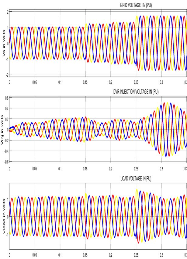
b. Voltage source inverter Pulse-Width Modulated VSI (PWMVSI), storage unit creates DC voltage. A VSI is the conversion of voltage from DC-AC voltage. at the time of sag, a step-up voltage injection transformer is increase magnitude of voltage. So, a minimum voltage value with VSI is enoughfig (a). c. Voltage injection of transformer The use of low passive Filters in this method in which the PWM inverted pulse waveform converted into a sinusoidal waveform. In VSI for the achievement of this conversion, it is compulsory to Fig .b. In-phase compensation remove high-value harmonic components while SDVR = K=a,b,c V′DVR . ILoad …..(1) DC-AC transformation, and it will also change the ′ is the rms of DVR injected voltage in phase K compensated output voltage. A passive filter is an where, ′ , k is the rms of DVR injected voltage in essential source in voltage inverter. If we put the phase k and load is rms of l ⱺoad current. The filters on the inverter side, it can overcome exchanged active power between the DVR and maximum value harmonics from passing through power grid is as follows: the voltage transformer fig (a). So, the stress on the PDVR = PLoad - Pgrid --------------- (2) injection transformer is also decreased by it. When = [ 3. . . ∅ the filter is placed in the inverter side and causes = , , ′ . . cos (∅) ]----(3) phase shift and voltage drop in inverted,that is the disadvantage of the filter. Thus, by putting the filter ′ = 2 . [ − ′ ]--------- (4) on the load side, this problem can be solved. The secondary side of the transformer permits the high In phase compensation technique minimise the valued harmonics currents because the voltage injected by the DVR. It also minimizing the transformer with high values is necessary. energy storage device it support both real and (iii) IN-PHASE COMPENSATION reactive power for the compensation. The in-phase compensation method is used for III. CONTROL OF DVR the active loads. Compensation is needed for voltage magnitude not for compensating phase The control algorithm of the DVR in which the SRF angel. Compensation and support of DVR which theory is used for the control of aself-supported means of storage (11) devices fig (c), it is used DVR. The voltages at PCC ( ) are converted to the when both the real and reactive powers are needed. rotating reference frame using theabc–dq0 Minimization of voltage amplitude in this method conversion using the Park’s transformation fig (c). where DVR fig (b) is to compensate the load voltage The harmonics and the oscillatory components with minimum voltage injection (10-11). voltage ofthe voltages are eliminated using low-pass filters compensation in phase to post sag value of PCC (LPFs). voltage. Hence by this method injected voltage (i) Park transformation magnitude can be minimized. Butsome of the Converts the time-domain components 3phase in cases, phase changes occur with voltage sag,[8] in an abc reference frame to direct, quadrature, and this method producesa distortions to the voltage zero components in a rotating reference frame fig load leading to transients and circulating currents (c). The active and reactive powers with the system fig (b). For sensitive load, in phase compensation is in abc reference frame by implementing an beneficial as it compared to other compensation invariant version. tripping of the load. Realize this compensation Zero component is equal to zero in balanced strategy, the phase locked loop (PLL) is system. It is mathematical transformation used to synchronized to the grid voltage itself, and not be simplify the analysis related to three-phase circuit. locked to the pre-sag grid voltage during the This techniques can be applied to reduce the three compensation. AC quantities of two DC quantities. It make the calculation and simulation is become simple. 17 International Journal for Modern Trends in Science and Technology
It the supply voltage equ(5) and reference voltage voltages are eliminated using low-pass filters
are transformed from abc coordinates to dq0 (LPFs). The components of voltages in d- and
coordinates with the help of adc_to_dq0 q-axes are
transformation block.[9] Vd = VdDC + VdAC --------(7)
The dq0 signal of both supply voltage and reference Vq = VqDC + VqAC --------(8)
voltage split using de-mux block. The direct Thecompensating of a strategy for compensation of
qudrature(d) and the (q) value of the supply signal. voltage quality problems considers that the
The resultant d and q is then sent to the loadterminal voltage should be of rated magnitude
dq0_to_abc transformation block equ( 5) with the and undistorted in nature.In order to maintain the
help of mux block is shown in fig(c). DC bus voltage of the self-supported capacitor, a PI
 controller is used at the DCbus voltage of the DVR
 and the output is considered as the voltage loss
 ( ) for meeting its losses:
 = ( −1) + 1 ( ( ) - −1 )
 ---(5)
 + 1 ( ) ----(9)
The dq0_to_abc transformationblock convert the Where,
resultant dq0 coordinates to abc coordinates ( ) = ∗ ( ) - ( ) ----------------(10)
output of the block fig (c) is then sent to the VSC
with harmonic filter unit fig (a). Where, = ∗ - is the error between the
Discrete three phase PLL block generates an reference DC voltage (V*DC)
output signal whose phase is related to the phase
of the input signal.The output from the PLL block is
sent to the abc_to_dq0 transformation and
dq0_to_abc transformation block. This helps to
generate the signal for pulse generator in phase
with the system voltage.Load voltages ( , , )
are converted to the rotating reference frame using
abc-dqo conversion using Park’s transformation
with unit vectors(sinθ, cosθ) and are derived using
a phase locked loop as, Similarly, reference load
voltages and voltages at ( , , PCC VS are also
converted to the rotating reference frame.
Then, the DVR voltages are obtained in the rotating
reference frame as, we obtain reference DVR
voltages in the abc frame from a [10] reverse Park’s
transformation as follows.The harmonics in the
voltage are eliminated using the low pass filters,
The components of voltages in the d-axis and Fig.c. control block of the DVR uses SRF method
q-axis respectively are The voltages at the PCC (VS)
are converted to the rotating reference frame using And sensed DC voltage(VDC) at the nth sampling
Park’s transformation (abc-dqo conversion). instant. Kp1 and Ki1 are the proportional and the
 integral gains of the DC busvoltage PI
 controller.Therefore, the reference d-axis load
 voltage is shown in fig ( b ),. The voltages at PCC ( )
 and the load terminal voltages ( ) aresensed to
 --(6) derive the IGBT gate signals.
The control algorithm of the DVR in which the SRF The reference load voltages ( ∗ , ∗ , ∗ ) are
theory is used for the control of aself-supported extracted using thederived unit vectors.The
DVR. The voltages at PCC ( ) are converted to the amplitude of the load voltage ( ) at PCC is
rotating reference frame using theabc–dq0 calculated as,
conversion using the Park’s transformation. The = [ (2 3 )1 2 (
 2 2
 + 2
 + )]^1/2----(11)
harmonics and the oscillatory components ofthe
 = - ---(12)

18 International Journal for Modern Trends in Science and Technology
The amplitude of the load terminal voltage ( ) is software using Sim-Power Systems (SPS)
controlled to its reference voltage ( ∗ ) using toolboxes. However, because of space limitation
anotherPI controller. and to give justbasic understanding a
The output of PI controller is considered as the capacitor-supported DVR are considered for the
reactive component of voltage ( ) forvoltage compensation of sag, swell, harmonics, and an
regulation of load terminal voltage. The amplitude unbalance in the terminal voltage for various
of the load voltage ( ) at PCC is calculatedfrom the injection schemes using SRF theory control
AC voltages ( , , ).The voltages at PCC ( ) and algorithm.
the load terminal voltages ( ) aresensed to derive Case 1: Compensation of voltage sag using DVR
the IGBT gate signals.The voltages at PCC ( ) and The performance of SRF-controlled
the load terminal voltages ( ) aresensed to derive capacitor-supported DVR for different supply
the IGBT gatesignals.The voltages at PCC ( ) and disturbances is tested under various operating
the load terminal voltages ( ) aresensed to derive conditions. A balanced voltage sag of amplitude
the IGBT gate signals. 0.75pu occurs 0.2 to 0.5. The waveform of
 disorted voltage, injected voltage ( ) and
 IV. SIMULATION AND OUTPUT compensated voltage ( ) is shown in case 1 fig
Fig (d), the performance of various topologies of (e). The load voltage ( ) is regulated at rated value,
three-phase DVR is simulated using MATLAB which shows the satisfactory performance of the
software using Sim-power Systems (SPS) DVR.
toolboxes. However, because of space limitation The sourcecurrent ( ), the amplitude of the load
and to give just basic understanding a terminal voltage ( ), the amplitude of the supply
capacitor-supported DVR are considered for the voltage ( ), andthe DC bus voltage ( ) are also
compensation of sag, swell, harmonics, and an shown in Figure (e) and (f), The DC bus voltage is
unbalance in the terminal voltage for various regulated at the reference value, although small
injection schemes using SRF theory control fluctuations occur during transients.
algorithm.DVR is simulated using MATLAB fig (d),

 Fig d. Simulation diagram capacitor supported DVR
Case 2: Compensation of voltage swell using FFT Analysis
DVR The voltage terminal at PCC is distressed through
A balanced voltage swell of amplitude 0.75pu the switching on a resistive load is succeed with
occurs from t = 0.25 to 0.3;.The waveform of sinusoidal with low harmonics , is balanced and
disorted voltage , injected voltage ( ) and get a constant magnitude due to the inserting of
compensated voltage ( ) is shown in case 2 voltage with help of the DVR. The total harmonic
fig(f).The harmonics compensation in supply Distortion (THD) for case 1 and case 2 are shown in
voltage is tested and depicted in Figure (e). The fig(g),. The THD of sag voltage and swell voltage is
voltage atPCC is disturbed by switching on and off shown below in fig (g), the THD is 4.66% and
a load in parallel at PCC. 4.92%.

19 International Journal for Modern Trends in Science and Technology
The loadterminal voltage ( ) has a THD of 4.66%
 for FFT analysis of 25 cycles with frequency of
 50Hz.

 Fig.g(a) total harmonic distortion swell
Fig.(e). Compensation of voltage sag (a) Grid voltage
(b) injected voltage (c)load voltage
The load terminal voltage ( ) isundistorted and
constant in magnitude due to the injection of
harmonic voltage ( ) by the DVR.

 Fig.g(b)Total harmonic distortion sag

 V. PARAMETERS FOR SIMULATION
 Parameter
 Value
 Name
 Line Impedance Ls 1mH,Rs 1ohm

 Load 5KVA,415V,pf:0.9lag

 Ripple Filter Cr 1µF,Lr 3.1Mh,Rr 1ohm

 DC bus capacitance Cdc 2000µF
 Fig.f. Compensation of voltage swell (a)supply AC line voltage V − -L 440V,50Hz
 voltage (b)injected voltage (c)load voltage PWM switching
 6Hz
 frequency
 Transformer 10KVA,150V/300V

20 International Journal for Modern Trends in Science and Technology
VI. CONCLUSION
In this these, the synchronous frame theory based
control scheme is proposed. The performance of
DVR has been verified through simulation using
MATLAB. The reference voltage for the DVR has
been attained indirectly by take out the reference
terminal voltage. Three phase harmonic filter is
used in this simlink DVR model that reduces the
harmonics generated by VSI. DVR performance in
mitigation numerous power quality complication
such as voltage dip, unbalanced conditions and
voltage swell, and has been observed and balanced
voltage at the load terminal.

 REFERENCES
[1] N. G. Hingorani and L. Gyugyi, Understanding FACTS:
Concepts and Technology of Flexible AC Transmission Systems.
New York, NY, USA:Wiley, 2010.
[2] W. Frangieh and M. B. Najjar, ``Active control for power
quality improvement in hybrid power systems,'' in Proc. 3rd Int.
Conf. Technol. Adv.Electr., Electron.Eng. (TAEECE), Apr.
2015,pp.218_223,doi:10.1109/TAEECE.2015.7113630.
[3] S. Agalar and Y. A. Kaplan, ``Power quality improvement
using STS and DVR in wind energy system,'' Renew. Energy, vol.
118, pp. 1031_1040,Apr. 2018,oi:
10.1016/j.renene.2017.01.013.
[4] W. Martiningsih, U.Y. Prakoso, and Herudin, ``Power quality
improvement using dynamic voltage restorer in distribution
system PT. DSS power plant,'' in Proc.MATECWeb Conf., vol.
218, Oct. 2018, p. 01003.
[5] M. Danbumrungtrakul, T. Saengsuwan, and P. Srithorn,
``Evaluation of DVR capability enhancement-zero active power
tracking technique,'' IEEE Access, vol. 5, pp. 10285_10295,
2017, doi:10.1109/ACCESS.2017.2706275.
[6] A. I. Omar, S. H. E. Abdel Aleem, E. E. A. El-Zahab, M.
Algablawy,and Z. M. Ali, ``An improved approach for robust
control of dynamic voltage restorer and power quality
enhancement using grasshopper optimization algorithm,'' ISA
Trans., vol. 95, pp. 110_129, Dec. 2019,
doi:10.1016/j.isatra.2019.05.001.
[7] Amit Kumar Jindal, ArindamGhosh and Avinash Joshi,
“Critical load bus voltage control using DVR under system
frequency variation”, Electric Power Systems Research, vol.78,
no.2, pp. 255-263, 2008.
[8] F. B. Ajaei, S. Farhangi, and R. Iravani, “Fault current
interruption by the dynamic voltage restorer,” IEEE Trans.
Power Del., vol. 28, no. 2, pp. 903–910, Apr. 2013.
[9] P. Kanjiya, B. Singh, A. Chandra, and K. Al-Haddad, “SRF
theory revisited to control self-supported dynamic voltage
restorer (DVR) for unbalanced and nonlinear loads,” IEEE
Trans. Ind. Appl., vol. 49, no. 5, pp. 2330–2340, Sep. 2013
[10] Ramachandaramurthy K. Improved fault ride through
capability in DFIG based wind turbines using dynamic voltage
restorer with combined feedforward and feed-back control.
IEEE Access 2017;5:20494–503.

21 International Journal for Modern Trends in Science and Technology
You can also read