Potential Impact of Evaporative Cooling Technologies on Australian Office Buildings - AIRAH
←
→
Page content transcription
If your browser does not render page correctly, please read the page content below
FORUM
P E E R - R E V I E W E D T E C H N I C A L PA P E R S

        Potential Impact of
        Evaporative Cooling Technologies
        on Australian Office Buildings
            Dr Paul Bannister, F.AIRAH, FIEAust, Director of Innovation, DeltaQ Consulting Services
            Hongsen Zhang, Director, Enerefficiency
            Dr Stephen White, F.AIRAH, Energy Efficiency Domain Leader CSIRO

        ABSTRACT
        This paper presents the results of a preliminary simulation-based study of the potential energy-efficiency benefits of a range
        of evaporative cooling technologies for Australian office buildings across the full range of Australian climates.

        It is found that dewpoint coolers offer the most promising savings potential (13–55 per cent) across climate zones 2–7
        (i.e., all climate zones other than Darwin and Thredbo). In climate zone 8 (Thredbo) it is shown that a direct/indirect evaporative
        cooling arrangement can wholly supplant the need for a chiller. Desiccant wheel systems were found to generate electricity
        savings in climate zones 1–4 but these were counteracted by the significant amount of energy required for desiccant reactivation.

        Overall, the results indicate that there is significant potential for the application of evaporative cooling technologies
        in Australian office buildings outside the tropics.

        INTRODUCTION                                                           • Chiller was modelled as a water-cooled chiller of IPLV8.7,
                                                                                 COP 6, using IES default chiller part-load characteristics,
        Evaporative cooling technologies do not currently play a
                                                                                 with a chilled water temperature rest based on outside
        significant role in commercial office building air conditioning,
                                                                                 air temperature.
        other than in cooling towers. In this paper, simulation
        modelling is used to test a range of direct and indirect               • Boiler was modelled as a condensing boiler of nominal
        evaporative cooling technologies applied to the airside                  90 per cent efficiency using detailed part load curves and a
        of a conventional VAV system serving a medium-sized                      hot water temperature reset based on outside air temperature.
        commercial office building.                                          Full details of the model are available in Zhang et al [2].
                                                                             The building form is shown in Figure 1.
        METHODOLOGY
        The office building was modelled in a thermal simulation
        package, with the following characteristics:
           • Eight-storey building with underground carpark.
           • 50 per cent window-wall-ratio (WWR). This is a typical
             WWR for the office building in Australia.
           • 25m by 25m floorplate, four perimeter and one centre
             zone per floor, the total area is 5,000m². The square
             floor plate was used to ensure the building orientation
             has no impact on the simulation result.
           • Floor-to-ceiling height is 2.7m. This is the typical
             floor‑to‑ceiling height for offices.                                          Figure 1. Building form as modelled.
                                                                             The building simulation was run in each NCC Volume 1
           • Plenum height is 0.9m. This is the typical plenum height
                                                                             [ABCB, 1] climate zone using IWEC weather data from ASHRAE
             for office buildings in Australia.
                                                                             for the following locations: CZ1 Darwin; CZ2 Brisbane;
           • Building façade and HVAC systems were modelled as               CZ3 Alice Springs; CZ4 Wagga Wagga; CZ5 Sydney;
             compliant with NCC 2019 Section J provisions [ABCB, 1].         CZ 6 Melbourne; CZ 7 Canberra; and CZ8 Thredbo.

 48     M AY 2021      •   ECO L I B R I U M
FORUM
HVAC CONFIGURATIONS OA
Direct
evap Supply
damper cooler fan
The HVAC configurations modelled are as follows:
• SC 1: A conventional VAV system as shown in Figure 2.
This is the baseline against which the evaporative
cooling scenarios are tested. Note that by default, the Return Occupied
design parameters of the evaporative cooling scenarios air damper space
are the same as this scenario unless required to change Return
fan
to match the revised configuration.
• SC 2a: A VAV system with direct and indirect Exhaust
damper
evaporative cooling as shown in Figure 3.
In this system, the indirect evaporative cooling works Figure 2. HVAC Configuration SC 1: a conventional
VAV system, used as the baseline scenario.
by saturating the exhaust air using water sprays or
similar and then operating a heat exchanger between
Direct
this evaporatively cooled airflow and the outside air OA evap Supply
damper cooler fan
intake. Direct evaporative cooling is also available to
the supply air. The design pressure drop across the
heat exchanger was modelled as 100Pa, and 52Pa for Outside
Heat Exchanger
air
the direct evaporative cooler, based on supplier data. fan
Occupied
Return
• SC 2b: This is a VAV system with a dew-point air damper space
cooler added to the outside air intake, plus direct Return
fan
evaporative cooling to the supply air as shown
in Figure 4. In a dewpoint cooler, notionally two Exhaust Direct
volumes of air are drawn through the cooler’s heat damper evap
cooler
exchanger, with one volume being passed into the
Figure 3. HVAC Configuration SC 2a: VAV system
building and the other volume circulated through
with direct and indirect evaporative cooling.
the other side of the cooler’s heat exchanger while
being saturated with water, and then rejected to
atmosphere. At the theoretical limit, a device of this OA
Direct
evap Supply
damper
nature could generate a supply airstream that has a cooler fan
Dew
dry-bulb temperature equal to the dewpoint of the point
cooler
outside air, hence the device’s name. The pressure Outside
air
drop through the dew-point cooler was modelled as fan
Return Occupied
150Pa, based on supplier data. air damper space
• SC 2c: This the same system as SC 2b except with
Return
no direct evaporative cooling. fan
• SC 3: This is a VAV system with direct and Exhaust
indirect evaporative cooling and a desiccant wheel, damper
as shown in Figure 5. The desiccant wheel removes Figure 4. HVAC Configuration SC 2b: VAV system with
moisture from the outside air prior to this entering dew-point cooler and direct evaporative cooling.
the indirect evaporative cooler heat exchanger.
The cooled and dried air is then better suited to OA
Direct
evap Supply
direct evaporative cooling (being pre-dehumidified) damper cooler fan
and furthermore, when the direct evaporative
cooler is not operating, will have a greater
Desiccant Wheel
Outside
Heat Exchanger
indirect evaporative cooling potential due to the air
fan
reduced humidity. This, however, comes at a cost: Return Occupied
air damper space
a significant amount of heat is used to reactivate
the desiccant wheel in the exhaust air path. Return
fan
The desiccant wheel was modelled with a pressure
drop of 180Pa, the heat recovery wheel at 135Pa Exhaust Direct
damper evap
(both based on supplier data) and the additional cooler
heating coil at 50Pa (based on a two‑row coil Figure 5. HVAC Configuration SC 3: VAV system with direct/
NCC2019 Table 5.4d). indirect evaporative cooling and a desiccant wheel.
50 M AY 2021 • ECO L I B R I U MFORUM
COMPONENT MODELS are described below. In all cases these were subject to a degree
of basic optimisation before being adopted.
Dew-point cooler
IES does not have a dedicated component for dew-point SC 1 Standard VAV
cooler, so it was necessary to create custom modelling for this. The following control was used:
The process of modelling for this component was as follows: • The zone set-point was set to be 22.5°C with 2°C deadband
• A data table was obtained from a supplier. and 0.5°C proportional band either side. The minimum
VAV turndown was set as 50 per cent for centre zones
• A multivariable regression equation was derived to calculate
and 30 per cent for perimeter zones.
the outlet dry bulb temperature based on the inlet dry bulb
temperature and moisture content, based on the data table. • The supply air temperature of the AHUs was modelled as
follows. The heating supply air temperature was reset from
• An additional cooling coil controlled to achieve the
30°C to 22.5°C for the average zone temperature from 21°C
outlet temperature based on the derived multivariable
to 21.5°C. The cooling supply air temperature was reset from
regression equation; the chiller energy associated with
22.5°C to 12°C for the average zone temperature from 23°C to
this cooling coil was then excluded from the results.
23.5°C. No heating or cooling is provided when the average
• The simulated outlet temperature from this arrangement
temperature of the zones is between 21.5°C to 23.5°C.
matched the table data well: 98.9 per cent of the data
• The economy cycle was modelled to achieve the target
points are within ±5 per cent of the difference.
outlet temperature reset from 22.5°C to 12°C for the average
Desiccant wheel zone temperature from 21.5°C to 22°C. The economy
Similarly, IES does not have a dedicated component model cycle is available when the outside air dew point is below
for a desiccant wheel, so a custom model was developed. 15°C, the outside air-dry bulb temperature is below 24°C
The process of modelling for this component was as follows: and the outside air-dry bulb temperature is less than the
return air‑dry bulb temperature. This control strategy is
• A combination of a cooling coil and a heating coil was
to ensure the economy cycle is operating before the chilled
used to mimic the performance of the desiccant wheel.
water comes into play when the conditions are appropriate.
• Based on manufacturer’s advice, the desiccant wheel has
• An efficient fan curve was used with an x2.7 turndown to
3g/kg moisture content removal at 55°C reactivation
30 per cent flow when no further decrease was assumed.
temperature and every g/kg moisture drop equates
This represents a variable pressure and variable volume fan
to a 3.3°C temperature rise of the supply air.
control. The overall fan efficiency was modelled as 60 per cent
• The cooling coil was used to overcool the incoming air
• The minimum outside air was modelled to be modulated
to achieve 3g/kg moisture content removal. The required
between 30 per cent and 100 per cent when the high select
temperature was calculated based on a regression
zone CO2 concentration changes from 800ppm to 1,000ppm.
equation derived from psychrometric formulas.
• The heating coil was used to model the temperature rise SC 2a Direct and indirect evaporative cooling
after the desiccant wheel. The energy consumed by the The control for this configuration is as follows:
cooling and heating coil was excluded from the result.
• The direct evaporative cooling is available when the average
• Another heating coil was used on the relief air duct to heat zone relative humidity (RH) is less than 60 per cent and the
the relief air to 55°C, which is the reactivation temperature post-economy-cycle wet bulb temperature is less than 14°C.
for the desiccant wheel. The energy consumption The direct evaporative cooler is controlled proportionally to
of this heating coil was included in the result. achieve an outlet RH ranging from 0 per cent to 95 per cent
The simulated performance matched the manufacturer’s as the zone temperature ranges from 22.5°C to 23°C.
guidance well when the outlet moisture content • The indirect evaporative cooling was modelled to be operating
was greater than 4g/kg. However, below this figure, when the average zone temperature is greater than 22°C.
the simulation underpredicts the moisture removal The outside air goes through the dedicated fan and heat
significantly, which will cause the simulation to exchanger when the outside air temperature is 4°C less than
underestimate the effectiveness of the wheel under the post-indirect cooler air temperature and average zone
these conditions. This issue is caused by limitations temperature is greater than 22°C, or when the outside air
in the use of regression formulae within IES. temperature is 4°C greater than the return air temperature and
the average zone temperature is less than 21.5°C. Otherwise
HVAC CONTROL the outside air is bypassed, and the dedicated fan does not run.
The sequencing of the various components in the test The heat exchanger efficiency was set to be 70 per cent.
configurations is critical to the energy efficiency of the systems. • The economy cycle control is based on the post heat
The baseline control configurations for the HVAC systems exchanger condition when the heat exchanger is in operation
M AY 2021 • ECO L I B R I U M 51FORUM
or otherwise based on the outside air temperature. Other SC 2c Dew-point cooler only
than this, the economy control for SC 2a is the same as that Controls for this configuration are identical to SC 2b
for SC-1. but without a direct evaporative cooler.
• The above control strategy gives the sequence of the HVAC
component in cooling mode as follows: Outside Air Economy SC 3: Direct/indirect evaporative cooling
Cycle → Indirect Evaporative Cooling → Direct Evaporative plus desiccant wheel
Cooling → Chilled Water Cooling This configuration is controlled as follows:
• Other controls for SC 2a are the same as those for SC 1. • The direct evaporative cooling is available when the average
zone RH is less than 60 per cent.
SC 2b Dew-point cooler plus
direct evaporative cooling • The indirect evaporative cooling was modelled
The controls for this configuration are as follows: to be operating when the average zone temperature
is greater than 22°C.
• The direct evaporative cooling is available when the average
zone RH is less than 60 per cent and the post dew-point • The heat recovery wheel is operating when the desiccant
cooler wet bulb temperature is less than 14°C. The direct wheel or the indirect evaporative cooler is in operation.
evaporative cooler is controlled proportionally to achieve an The efficiency of the heat recovery wheel was set as
outlet RH ranging from 0 per cent to 95 per cent as the zone 70 per cent.
temperature ranges from 22.5°C to 23°C. • The economy cycle control is based on the post heat
• The dew-point cooler was modelled to be operating when the exchanger condition when the desiccant wheel/indirect
average zone temperature is greater than 22°C, the outside evaporative cooling is in operation or otherwise based on
air dewpoint is less than 21°C1 and the outside air-dry bulb the outside air temperature. Other than this, the economy
temperature is greater than 12°C. The outside air goes through control for SC 3 is the same as that for SC 1.
the dedicated fan and the dew-point cooler if the above • The above control strategy gives the sequence of the HVAC
conditions are satisfied. Otherwise, the outside air is bypassed, component in cooling mode as follows: Outside Air Economy
and the dedicated fan and dew-point cooler do not run. Cycle → Indirect Evaporative Cooling → Direct Evaporative
• The economy cycle control is based on the post dew-point Cooling → Desiccant Wheel → Chilled Water Cooling.
cooler condition when the dew-point cooler is in operation • Other controls are the same as those for SC 1.
or otherwise it is based on the outside air temperature.
Other than this, the economy control for SC 2b is INITIAL SIMULATION RESULTS
the same as that for SC 1.
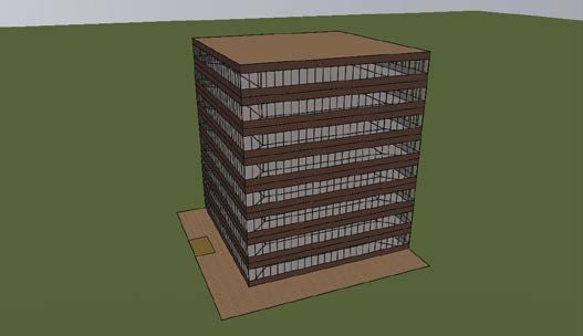
The basic results of the simulations, showing electricity
• The above control strategy gives the sequence of the HVAC consumption for all HVAC components (electricity – fans,
component in cooling mode as follows: pumps, chillers; gas – boiler) are presented in Figure 6 to
Outside Air Economy Cycle → Dew-point cooler → Figure 10. Note that for greenhouse gas emissions calculations,
Direct Evaporative Cooling → Chilled Water Cooling 2020 national average figures of 0.77kg/kWh for electricity
• Other controls are the same as those for SC 1. and 0.21kg/kWh for gas have been used.
40
35
SC1 SC2a SC2b SC2c SC3
30
Electricity (kWh/m²)
25
20
15
10
5
0
Zone 1 Zone 2 Zone 3 Zone 4 Zone 5 Zone 6 Zone 7 Zone 8
Climate Zone
Figure 6. Simulated electricity use.
1 This figure was selected as notionally optimal, within the constraints of the modelling, after some testing of different figures.
52 M AY 2021 • ECO L I B R I U MFORUM
80
70
60
50
Gas (kWh/m²)
40
30
20
10
0
Zone 1 Zone 2 Zone 3 Zone 4 Zone 5 Zone 6 Zone 7 Zone 8
SC1 SC2a SC2b SC2c SC3
Climate Zone
Figure 7. Simulated gas use.
35
30
25
Greenhouse(kg/m²)
20
15
10
5
0
Zone 1 Zone 2 Zone 3 Zone 4 Zone 5 Zone 6 Zone 7 Zone 8
SC1 SC2a SC2b SC2c SC3
Climate Zone
Figure 8. Simulated greenhouse emissions.
50
40
in greenhouse emissions
30
Percentage reduction
20
10
0
-10
-20
-30
-40
-50
-60 -114% -58% -155% -89% -63%
-70
SC2a SC2b SC2c SC3
-80
-90 Climate Zone
Figure 9. Simulated reduction in greenhouse emissions relative to SC 1.
M AY 2021 • ECO L I B R I U M 53FORUM
100%
90%
Reduction in chiller energy
SC2a SC2b SC2c SC3
80%
70%
60%
50%
40%
30%
20%
10%
0%
Zone 1 Zone 2 Zone 3 Zone 4 Zone 5 Zone 6 Zone 7 Zone 8
Climate Zone
Figure 10. Simulated reduction in chiller energy relative to SC 1.
It can be seen from the figures that: additional direct evaporative cooling, which provides
• None of the technologies is effective in Climate zone 1 (Darwin). positive results in all climate zones bar CZ1 and CZ8 and is
furthermore a relatively simple modular addition to a design
• Configuration SC 2a (direct/indirect evaporative cooling)
or even as a retrofit. The major constraint in the application
presents significant benefits in dry climate zones (CZ 3
of dewpoint coolers appears to be the limited maximum size
Alice Springs, CZ4 Wagga Wagga, CZ7 Canberra and CZ8
of individual units and the associated space requirements.2
Thredbo). Total greenhouse savings are in the region of
It is further noted that systems with a higher minimum
12–44 per cent, driven by chiller energy use reductions of
supply air temperature, such as underfloor systems, would be
54–99 per cent. In CZ8 (Thredbo) SC 2a essentially removed
the need for a chiller. expected to yield greater savings than reported in this paper.
• Configurations SC 2b and SC 2c (dew-point cooler with/
FURTHER CONTROL
without direct evaporative cooling) present significant
benefits in all climate zones other than CZ1 Darwin and CZ8 OPTIMISATION OF SC 2C
Thredbo. Except in Climate Zone 3 (Alice Springs) the direct In SC 2c the dew-point cooler is operated when conditions
evaporative cooling component offers no benefit beyond the permit at a zone temperature of 22°C. This supplements
dewpoint cooler. SC 2c (Dew-point cooler only) provides the economy cycle, which is enabled when conditions
greenhouse savings of 13–38 per cent driven by chiller energy permit at a zone temperature of 21.5°C to 22°C.
use reductions of 23–83 per cent. However, the chilled water cooling comes into operation
• Configuration SC 3 (Direct/indirect evaporative cooling with between 23°C and 23.5°C, meaning that the chiller is
desiccant wheel offers no benefit except in Climate Zone 8, called in to bring the supply air temperature down to 12°C
where a greenhouse emissions reduction of 14.5 per cent is before the VAV starts increasing air volume (from 23.5°C
achieved and the evaporative technologies completely replace to 24°C). This reduces the extent to which the system can
all cooling, obviating the need for a chiller. In the situation operate solely on the dewpoint cooler. To examine the
where “free” heat is available for desiccant reactivation, SC potential for greater use of the dewpoint cooler, a series
3 achieves a modest electricity saving in Climate zones 1–4; of additional scenarios was run as follows:
however, other than in Climate Zone 1, this system is still • SC 2c-2: When the dew-point cooler is operating, the
outperformed by other options. supply air temperature set-point controlling the chilled
Note that differences between the reductions in chiller energy and water valve drops from 22.5°C to 12°C as the zone
the total change in electricity consumption are caused primarily temperature rises from 23.5°C to 24°C.
by increases in fan energy caused by higher air flows (driven by • SC 2c-3: When the dew-point cooler is operating,
higher supply air temperatures) and by the pressure drops across the supply air temperature set-point controlling the
additional components. There may therefore be options to improve chilled water valve drops from 22.5° to 12°C as the zone
the outcomes achieved with evaporative cooling by re‑examining temperature rises from 23.25°C to 23.75°C.
duct and coil sizes to minimise the impact of generally higher air
• SC 2c-4: When the dew-point cooler is operating,
volumes. This was not considered in this study.
the supply air temperature set-point controlling the
The overall conclusion from these results is that the most chilled water valve drops from 22.5° to 12°C as the zone
robust technology tested was the dew-point cooler, without temperature rises from 23.75°C to 24.25°C.
2 The largest dewpoint cooler in the Seeley Climate Wizard range has a supply air volume
of 12,800l/s and a plant footprint of approximately 15m2 [Seeley International, 3]
54 M AY 2021 • ECO L I B R I U MFORUM
60%
GHG reduction relative to SC1
50%
SC2c SC2c-2 SC2c-3 SC2c-4
40%
30%
20%
10%
0%
Zone 3 Zone 5 Zone 6 Zone 7
Climate Zone
Figure 11. Impact of further control optimisation of SC 2c
In each of the above scenarios, when the dew-point cooler is not underfloor systems. Overall, there is a strong case for greater use
operating, the supply air temperature set-point controlling the of evaporative cooling in Australian office buildings.
chilled water valve control operates as per SC 2c. The results
Work reported in this paper was undertaken
in terms of greenhouse emissions are shown in Figure 11 for a
for the PRIME Net Zero Energy HVAC
subset of climate zones. Technology Road Map project.
The achieved savings show some sensitivity to the detail of
control, dependent on climate, most significantly for the arid REFERENCES
Climate Zone 3 (Alice Springs). In other climate zones, the 1. Australian Building Codes Board, National Construction
impacts are somewhat more marginal. In all cases, the different Code 2019. Available from www.abcb.gov.au.
2. Zhang, H., Bannister, P., and White, S. Low Carbon CRC
control scenarios cause only minor modulation of the chiller and Net Zero Energy HVAC Technology Options Simulation
fan energy and do not fundamentally change the operation of the Report, November 2018. Available from the authors.
system. 3. Seeley International cw80 twin technical specification, available
from https://www.seeleyinternational.com/artefact/cw80t-
twin-technical-specifications-metric/ Accessed 5 July 2020.
CONCLUSION
A simulation model in IES-VE of a 5,000m2, NCC 2019 Section
J compliant office building with a VAV system has been used to ABOUT THE AUTHORS
test a range of evaporative cooling technologies across the major
Dr Paul Bannister, F.AIRAH
Australian climate zones. Dr Paul Bannister is a leading energy efficiency consultant who has
experience in projects and policy development in Australia and
Overall, the results indicate that the dew-point cooler is the most overseas. He is a specialist in commercial building energy efficiency
robust evaporative cooling system, with strong applications in and is the technical author of the NABERS Energy and Water
ratings. He also led the NCC2019 revision project. He has published
arid climate zones 3 and 4 (greenhouse gas savings of 13–55 per extensively on energy efficiency and renewable energy over the
cent) and smaller but significant savings in climate zones 2, 5, 6 past 30 years.
and 7 (13–19 per cent) The modular nature of dew-point coolers Paul.Bannister@dqcs.com.au
means that they are a potential retrofit option for building with Hongsen Zhang
sufficient roof space although that there are limits on the size of Hongsen Zhang is an energy efficiency consultant with 20 years of
academic and industry experience. He is a leading energy modeller
available units that may restrict applicability in larger buildings. in the industry. He has completed more than 50 high‑quality
simulation projects for both new and existing buildings, and
In Climate Zone 8, it has been demonstrated that a direct/indirect intensively used simulation to support policy development projects.
evaporative cooling combination (SC 2a) can effectively supplant He was the simulation team leader for the NCC2019 Section J
revision project. Hongsen has published 15 peer-reviewed papers in
the need for a chiller, making this system potentially viable. the field of HVAC and energy efficiency in buildings.
Hongsen.Zhang@enerefficiency.com
Evaporative cooling is rarely applied in office buildings in
Australia. Given the substantial savings possible, and the Dr Stephen White, F.AIRAH
pressure to drive office buildings towards net zero emissions, Dr Stephen White leads CSIRO’s Energy Efficiency Research. He also
leads the “Buildings to Grid Data Clearing House” activity in the
there appears to be a good argument for the use of evaporative Affordable Heating and Cooling Innovation Hub (i-Hub). He is the
cooling to drive HVAC efficiency beyond the current boundaries operating agent for the International Energy Agency EBC Annex 81
“Data-Driven Smart Buildings”. He was a program leader in the Low
of best practice VAV systems. Carbon Living Cooperative Research Centre. He is a member of the
Australian Refrigeration and Building Services (ARBS) Hall of Fame.
Furthermore, the potential savings may be higher for HVAC Stephen.D.White@csiro.au
systems with higher minimum supply air temperatures, such as
M AY 2021 • ECO L I B R I U M 55You can also read