Verizon SMARTS Data Center Design Phase 1 Conceptual Study Report Ms. Leah Zabarenko Verizon Business 2606A Carsins Run Road Aberdeen, MD 21001
←
→
Page content transcription
If your browser does not render page correctly, please read the page content below
Verizon SMARTS Data Center Design Phase 1
                 Conceptual Study Report
                           Ms. Leah Zabarenko
                              Verizon Business
                        2606A Carsins Run Road
                          Aberdeen, MD 21001

                                        Presented by:
                              Liberty Engineering, LLP
               1609 Connecticut Avenue NW, Suite 200
                                Washington, DC 20009

                             ISSUE FOR BID & PERMIT
                                        31 JULY 2014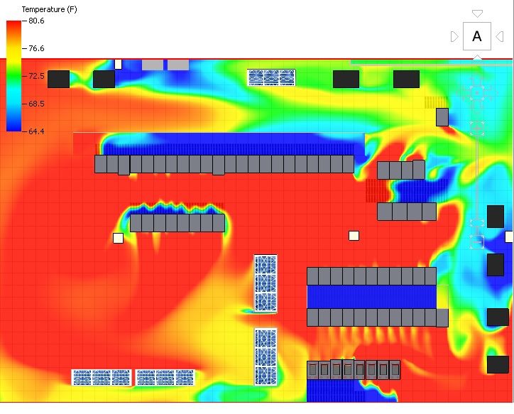
Presentation Narrative – Verizon SMARTS Data Center Design Phase 1
TABLE OF CONTENTS
EXECUTIVE SUMMARY .................................................................................................................................. 3
INTRODUCTION ............................................................................................................................................. 4
METHODOLOGY ............................................................................................................................................ 4
ASSUMPTIONS .............................................................................................................................................. 5
EXISTING CONDITIONS .................................................................................................................................. 5
SMARTS PROJECT .......................................................................................................................................... 5
CONCEPTUAL DESIGN OPTIONS .................................................................................................................... 6
Option 1 – CRAH Units ............................................................................................................................. 6
Option 2 – IRC Units ................................................................................................................................. 6
ANALYSIS ....................................................................................................................................................... 6
OPTION 1....................................................................................................................................................... 8
OPTION 2..................................................................................................................................................... 11
COST ESTIMATE........................................................................................................................................... 14
SUMMARY AND RECOMMENDATIONS ....................................................................................................... 14
APPENDICIES ............................................................................................................................................... 15
APPENDIX 1 – Air Temperature at 40” AFF For Option 1 Normal Operation ........................................ 15
APPENDIX 2 – Air Temperature at 40” AFF For Option 1 Failure Operation ......................................... 16
APPENDIX 3 – Air Temperature at 40” AFF For Option 2 Normal Operation ........................................ 17
APPENDIX 4 – Air Temperature at 40” AFF For Option 2 Failure Operation ......................................... 18
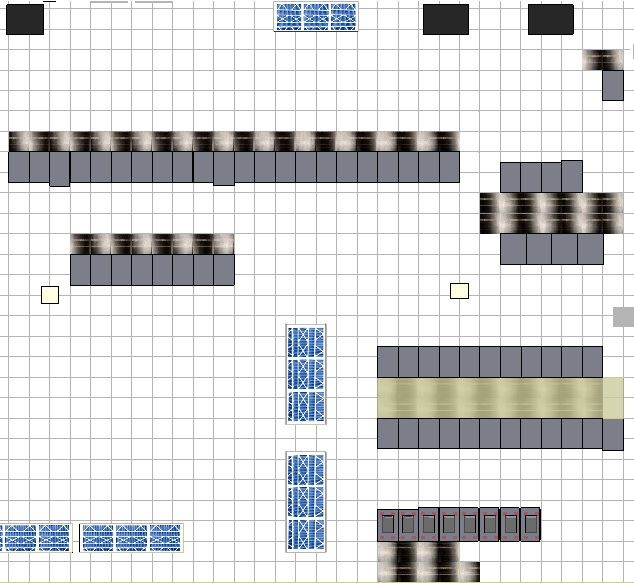
APPENDIX 5 – Conceptual Floorplan of Equipment Racks ..................................................................... 19
APPENDIX 6 – Calculations ..................................................................................................................... 21
APPENDIX 7 – CAD Drawings ................................................................................................................. 22
Project Number 20.14008.00 Issue for Bid and Permit
31 July 2014 Page 2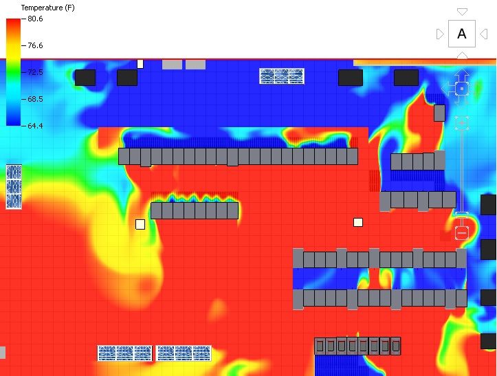
Presentation Narrative – Verizon SMARTS Data Center Design Phase 1

EXECUTIVE SUMMARY
Verizon Business requested Liberty Engineering, LLP to perform a conceptual study to compare two (2)
mechanical design options for providing the required heat removal for the addition of proposed
equipment associated with the SMARTS project. This project will add rack mounted technology
equipment in the CPU Room in the Perryman Data Center in Aberdeen, MD. The study utilized
Computational Fluid Dynamics (CFD) modeling of the two (2) options to evaluate the effectiveness in
meeting the new equipment thermal requirements. Additionally, a ROM cost comparison of the two
options was developed for comparison purposes. From this study Verizon will select a preferred option
to implement as the final design for the HVAC system modification.

The study utilized two different options to evaluate the required cooling capacity needed within the
space and determine if any hotspots existed. Each option has been thermally modeled in a three
dimensional CFD program to simulate the HVAC performance of the mechanical system and rack layout.
The two options are:

    •   Option #1 – The addition of two CRAH units.
    •   Option #2 – The addition of twelve In-Row Cooling (IRC) units.

These results were compared against one another to analyze the air temperature distribution
throughout the area in the CPU Room where equipment is being added. The temperature distribution
throughout the room was analyzed to determine which of the two options best supported the addition
of new equipment.

Each room layout accounts for 31 racks at 10 kW of load each and 4 racks at 3 kW each. Each rack was
modeled with all server positions filled and an equal distribution of load across the frame. The racks are
configured with a front intake, rear discharge air distribution, with 8 existing racks having an additional
top discharge.

The equipment load calculated has a sensible cooling requirement of approximately 98 Tons. The data
center is modeled using Liebert CW181 CRAH units that supply cool air at 56.7°F DB with a relative
humidity of 95% in Option 1. In Option 2, the data center is modeled using Liebert CR040RC In Row
Cooling units that supply cool air at 56.9°F DB with a relative humidity of 95%. A total of two 60.9-Ton
CRAH with N+1 redundancy with new and existing supply and return grilles comprise Option 1. In Option
2, twelve IRC’s with N+2 redundancy and new and existing supply and return grilles are provided.

Using the program 6Sigma, a CFD computer program, both models were created to determine which
concept was most effective. Results showed that Option 1, provides more effective heat removal. This
option was able to handle an outage much more successfully than the IRC option. Additionally, Option 1
is estimated to produce a savings of $320,017 versus Option 2.

For the reasons stated above, Liberty Engineering recommends Option 1, to be implemented in the final
design.

Project Number 20.14008.00                                                   Issue for Bid and Permit
31 July 2014                                       Page 3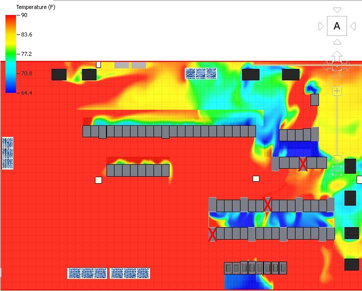
Presentation Narrative – Verizon SMARTS Data Center Design Phase 1

INTRODUCTION

Verizon is planning to install a new technology deployment project named "SMARTS" that will add new
equipment to the CPU Room of the Perryman Data Center (PDC) located in Aberdeen, MD which will
require utility infrastructure modifications to meet the equipment requirements. This will include
upgrades to both the mechanical HVAC and electrical power systems. To identify the required
mechanical system modifications, Verizon has requested Liberty Engineering to perform a conceptual
study of two different options to provide heat removal for the SMARTS equipment. Option 1 utilizes
Computer Room Air Handling (CRAH) units and Option 2 utilizes In Row Cooling (IRC) units, both fed
from the existing chilled water system. This report provides an analysis and recommendations of the
two (2) options to allow Verizon to select which one will be implemented for the final design. The
report is presented as follows. First a description of the methodology and key assumptions used to
create the report is provided followed by a description of the existing conditions and the proposed
SMARTS project. Then a description of the two conceptual mechanical design options, an analysis of the
options under specific operating scenarios, and a summary of the analysis with recommendations are
provided. Supporting documentation is included in an Appendix for reference to the different sections.

METHODOLOGY

To create the requested report, Liberty performed a site survey to assess the existing conditions of the
facility. Liberty then reviewed the proposed SMARTS equipment provided by Verizon to identify the
mechanical design requirements. The owner provided SMARTS equipment included a conceptual floor
plan layout of the equipment racks, their associated heat load, and air distribution configuration (see
Appendix 5 for reference). From this, two conceptual design options for the required heat removal were
developed to address the SMART equipment requirements within the constraints of the existing data
center. The concept designs developed included the location and sizes of the required HVAC
equipment, the air distribution system, and the chilled water hydronic system. The conceptual layouts
are included in Appendix 7 with supporting design calculations and equipment selections included in
Appendix 6. The concept designs were then modeled using Computational Fluid Dynamics (CFD)
modeling software to assess their heat removal effectiveness under two operating scenarios: NORMAL
and FAILURE. Normal operation is defined as having all HVAC equipment available at the design heat
load of the data center equipment. Failure operation is defined as only having the non-redundant
mechanical equipment available at the full design load conditions. The CFD results for each option
under the two operating scenarios were then analyzed and compared to each other utilizing
recommended operating temperature criteria for technology equipment as defined by ASHRAE. A
Rough Order of Magnitude (ROM) cost estimate was created for each option for comparison, as well.
The comparative analysis was then summarized with Liberty's recommendations as a conclusion to the
report.

The program utilized for the analysis of each option, 6Sigma (Release 8), is a computational fluid
dynamic computer program that three-dimensionally simulates air temperature, velocity, airflow path
and pressures within the model. At any location, the user can graphically and numerically see the
temperature, humidity, and velocity to validate if the proposed design solution meets the design
criteria. The program is specifically created for the analysis of data centers and provides highly detailed
output data. It has the ability to analyze actual manufacturers of equipment and different models to
account for unique aerodynamic shapes, thermal properties of materials and their variance in heat
exchange. The Racks, CRAHs, IRCs, and PDUs were not available in the program’s library, so general

Project Number 20.14008.00                                                   Issue for Bid and Permit
31 July 2014                                       Page 4
Presentation Narrative – Verizon SMARTS Data Center Design Phase 1

equipment was modified to match the dimension and capacity of the existing units and units used in the
design.

ASSUMPTIONS

    1. During Normal Operation, the inlet temperature to the equipment will be compared to a mean
        inlet temperature of 64.4°F to 80.6°F, the recommended temperature range per ASHRAE TC 9.9.
    2. The maximum allowable inlet temperature to the racks is 90°F during a failure condition, which
        is the maximum acceptable temperature per ASHRAE TC 9.9.
    3. Failure Operation for Option 1 will be defined as one (1) CRAH unit being unavailable.
    4. Failure Operation for Option 2 will be defined as three (3) in-row coolers being unavailable.
    5. The rack configuration is based on customer provided information.
    6. Racks are assumed to be 10kW unless otherwise noted in configuration provided by customer.
    7. The Liebert CRAH unit’s mode of operation is a constant supply temperature of 56.7°F.
    8. The Liebert IRC unit’s mode of operation is a constant supply temperature of 56.9°F.
    9. 31 of the new racks will operate at 10kW
    10. 4 of the new racks will operate at 3kW
    11. Racks are front inlet and rear outlet, with units in Row 79 having an additional top outlet.
    12. Failure analysis includes failure of a single power distribution path.
    13. Racks, cooling equipment plan south of column line four (4) do not impact the build out, and do
        not need to be modeled.
    14. There is a wall added at column line 4, since the area beyond it is not modeled.
    15. There is cold aisle containment in the aisle between Row 83 and Row 87.

EXISTING CONDITIONS

The existing conditions are based on the information provided by the customer, as well as information
gathered from site surveys. There is a 30 inch raised floor, and a drop ceiling 8 feet above the raised
floor. There are 31 existing storage racks, and 1 existing network rack. Existing racks are found in Rows
96, 95, 83, and 79. Racks are arranged to create hot and cold aisles. The area has two (2) 30 Ton, two (2)
40 Ton, and two (2) 28 Ton CRAHs. All the CRAH units have plenums to the drop ceiling, which allows
them to draw air from hot aisles through the return grilles in the drop ceiling. The average height of the
return plenum above the ceiling ranges, but all are between 1’-9” to 2’-1/2”. Vented floor tiles are
placed throughout the area in cold aisles. Cold aisle containment is in place in 2 areas: the cold aisle for
a portion of Row 79, and the area north of Row 96. There are also 8 PDUs. 4 Panelboards are in the
space being modeled, but they are not the only ones utilized to power the equipment shown. The
chilled water system being utilized is a below floor redundant pipe loop distributed from the 3000 Ton
chiller plant. The variable flow distribution system is a primary chilled water system with 3 pumps. The
system operates with a 50°F supply and 64°F return temperature per the design. There are pathways
present for power and network cabling in the form of below floor conduits, troughs, and cable trays
below the drop ceiling.

SMARTS PROJECT

The SMARTS project calls for the addition of 35 new racks, 31 at 10kW, and 4 at 3kW. 22 of the 10kW
racks will be in an area with cold aisle containment. The remaining racks will not have cold aisle

Project Number 20.14008.00                                                   Issue for Bid and Permit
31 July 2014                                       Page 5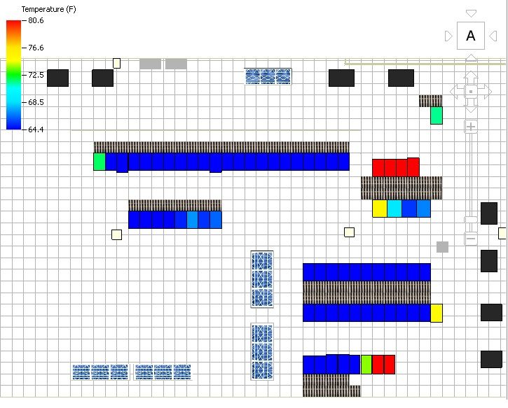
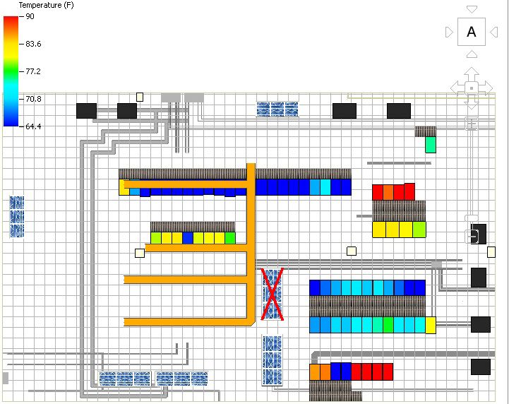
Presentation Narrative – Verizon SMARTS Data Center Design Phase 1

containment. To support this extra heat load, additional heat removal must be installed. Two concept
design are provided as options for this required heat removal for the scope of this study.

CONCEPTUAL DESIGN OPTIONS

Option 1 – CRAH Units
The concept behind Option 1 is to utilize four (4) existing to remain CRAH units, and add two (2) Liebert
CW181 units. The new CRAHs are chilled water hydronic units. The two (2) units will provide N+1
redundancy, and will be powered from different panels to match the redundancy. All CRAH units will
supply air to the racks through perforated tiles, via the raised floor. All CRAH units will have a plenum
connecting to the drop ceiling and will draw hot air from aisles through return grilles. Under Normal
Operation, all CRAH units will be cooling the area. During Failure Operation, one of the two new CRAH
units is assumed to fail. See Figure 1 for Option 1 Layout.

Option 2 – IRC Units
Option 2 will utilize four (4) existing to remain CRAH units, and add twelve (12) Liebert CR040RC IRCs.
IRCs will be placed strategically in the rack rows to provide cold air effectively to the new racks being
added. Due to the units being in-row, racks will need to be relocated to accommodate the units. There is
a redundancy of N+2 for these units, and they will be fed from 4 different panels to match the
redundancy. During Normal Operation, all cooling units will run as designed. Failure Operation is
modeled as 3 IRCs unavailable. See Figure 4 for Option 2 Layout.

ANALYSIS

There were two scenarios used for each of the options, a Normal Operation and Failure Operation.
Normal Operation is defined as having all cooling systems available. Failure Operation for Option 1
removes one CRAH unit from operation, and removes 3 IRC from operation for option 2. For Option 1,
rack locations were preserved, and CRAH units were placed advantageously near the new racks.

Each output from the CFD simulation was analyzed to determine if the operating conditions met the
acceptance criteria provided by the customer for satisfactory operation. Under normal operating
conditions, with all units enabled, the allowable mean rack inlet temperature is 64.4°F to 80.6°F, as
recommended by ASHRAE TC 9.9 guidelines. During Failure Operation, the maximum allowable rack inlet
temperature is 90°F, as recommended by ASHRAE TC 9.9 guidelines.

The CFD simulation produced three outputs that were found to be useful during the analysis process:
the median rack inlet temperature under Normal Operation, the maximum rack inlet temperature under
Failure Operations, and the air temperature at half-rack elevation (40” AFF).

The first output, the median rack inlet temperatures under Normal Operation, illustrates rack inlet
temperatures ranging from 64.4°F to 80.6°F depicted by a color gradient. This output was utilized as
one of two determining factors for whether an option passed or failed in regards to heat removal
effectiveness.

The second output, the maximum rack inlet temperatures under failure operation, illustrates rack inlet
temperatures ranging from 64.4°F to 90.0°F depicted by a color gradient. This output was utilized as the

Project Number 20.14008.00                                                   Issue for Bid and Permit
31 July 2014                                      Page 6
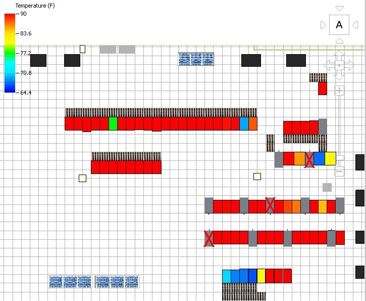
Presentation Narrative – Verizon SMARTS Data Center Design Phase 1

second of the two determining factors for whether an option passed or failed in regards to heat removal
effectiveness.

The third output exhibiting the air temperature distribution is a two-dimensional image showing the air
temperature throughout the CPU Room at 40” AFF. Air temperatures range from 64.4°F to 90°F and
were characterized by a color scale. This output was useful to identify hot spots, recognize recirculation
issues, and visualize the direction of airflow in each area.

The expanded rack layout provided by the customer has a total power consumption of 347kW, or 98
Tons of cooling. Accounting for the additional lighting, skin loads, and existing racks, the total heat load
of the room is calculated to be 666.2 kW, or 189.4 Tons. Based on the overall loads and capacities, the
CRAHs in option 1 will operate with N+1 redundancy. For Option 2, the IRCs will provide 11.37 Tons of
cooling each, but are most effective in close proximity to the racks.

Project Number 20.14008.00                                                    Issue for Bid and Permit
31 July 2014                                       Page 7
Presentation Narrative – Verizon SMARTS Data Center Design Phase 1

OPTION 1

The design for Option 1 incorporates the addition of two (2) CRAH units to offset the additional load
being added by the new racks. This cold air is distributed through the space by 2’x2’ 56% open
perforated floor tiles via the raised floor. Returns grilles are placed in the drop ceiling above the hot
aisles, to return the exhaust air to the CRAHs and minimize recirculation. Figure 1, below, shows the
design concept for Option 1:

                                                                                              Row 99

   Row 96
                                                                                                         Row 95

                                                                            Row 91
 Row 91

                                                       Row 87

                                                        Row 83

                                                                                               Row 79

                                          Figure 1 – Option 1 Layout

Project Number 20.14008.00                                                    Issue for Bid and Permit
31 July 2014                                       Page 8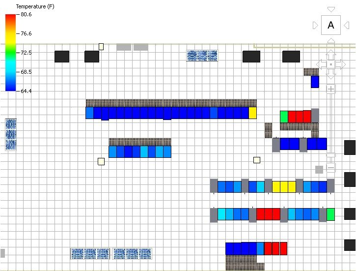
Presentation Narrative – Verizon SMARTS Data Center Design Phase 1

The median rack inlet temperatures for Option 1 during Normal Operation are shown in Figure 2. To see
additional room condition results from the CFD modeling for Option 1 during Normal Operation, see
Appendix 1.

                                                                                    Row 99

          Row 96
                                                                                             Row 95

                                                                                               Row 91
                   Row 91

                                                                                               Row 87

                                                                                                  Row 83

                                                                                      Row 79

                     Figure 2 – Option 1 Normal Operation Mean Rack Inlet Temperatures

Observations for Option 1 Normal Operation:
   • During Normal Operation, 4 racks in Row 95 exceed the maximum recommended temperature
       of 80.6°F.
   • 2 Racks in Row 79 exceed the maximum recommended temperature of 80.6°F. Since racks in
       Row 79 are not new, this may be an error due to a wall being placed south of these racks for the
       purposes of this simulation.
   • During Normal Operation, Only 1 rack, 10.95, exceeds the maximum allowable temperature of
       90°F.

Project Number 20.14008.00                                                   Issue for Bid and Permit
31 July 2014                                      Page 9
Presentation Narrative – Verizon SMARTS Data Center Design Phase 1

For the Failure Operation of Option 1, one of the new CRAH units is removed from operation. There
were no other changes to the model. Maximum rack inlet temperatures for this model can be found in
Figure 3. Other CFD outputs for Option 1’s failure operation, including the Air Temperature at 40” AFF,
can be found in Appendix 2.

                                                                                                Row 99

                Row 96                                                                     Row 95

                                                                                              Row 91
                         Row 91

                                                                                              Row 87

                                                                                                Row 83

                                                                                     Row 79

                  Figure 3 – Option 1 Failure Operation Maximum Rack Inlet Temperatures

Observations for Option 1 Failure Operation:
   • During Failure Operation, 4 racks in Row 79 exceed the maximum allowable temperature of
       90.0°F.
   • 3 racks in Row 95 exceed the maximum allowable temperature of 90°F during Failure Operation.
   • Other than the racks in Rows 79 and 95, racks are operating within the acceptable 64.4°F to 90°F
       temperature range during Failure Operation. Since racks in Row 79 are not new, this may be an
       error due to a wall being placed south of these racks for the purposes of this simulation.

Option 1 Summary of Observations:
   • During Normal Operation, 6 racks exceed the maximum recommended temperature, and only 1
       rack exceeds the maximum allowable temperature.
   • During Failure Operation, 7 racks exceed the maximum allowable temperature.

Project Number 20.14008.00                                                   Issue for Bid and Permit
31 July 2014                                      Page 10
Presentation Narrative – Verizon SMARTS Data Center Design Phase 1
OPTION 2
Option 2 utilizes IRCs being placed in Rows 83, 87, 91, 95. The IRCs are intended to be the sole source of
cooling in those aisles, therefore perforated tiles and return grilles are not added. The cold aisle
between Row 83 and Row 87 will have containment installed. The design concept for option 2 is shown
in Figure 4.
Row 99
Row 96
Row 95
Row 91
Row 91
Row 87
Row 83
Row 79
Figure 4 – Option 2 Layout
Project Number 20.14008.00 Issue for Bid and Permit
31 July 2014 Page 11Presentation Narrative – Verizon SMARTS Data Center Design Phase 1
The locations of the new IRCs are selected to maximize the impact of the units on the racks. In the
design, there are no more than four (4) racks between each IRC. The existing to remain CRAHs have
minimal impact on the new racks in this option affecting them only through the return grilles already in
place at the hot aisles. Median rack inlet temperatures for this model can be found in Figure 5. Other
CFD outputs for Option 2, including the Air Temperature at 40” AFF, can be found in Appendix 3.
Row 99
Row 96 Row 95
Row 91
Row 91
Row 87
Row 83
Row 79
Figure 5 – Option 2 Normal Operation Median Rack Inlet Temperatures
Observations for Option 2 Normal Operation:
• During Normal Operation, 3 racks in Row 95 exceed the recommended median rack inlet
temperature.
• During Normal Operation, 3 racks in Row 83 exceed the recommended median rack inlet
temperature.
• 3 Racks in Row 79 exceed the recommended median rack inlet temperature during Normal
Operation. Since racks in Row 79 are not new, this may be an error due to a wall being placed
south of these racks for the purposes of this simulation.
• All racks are within the maximum allowable inlet temperature.
• Other than Rack 07.95 and racks in Row 79, racks are operating within the acceptable 64.4°F to
80.6°F temperature range.
Project Number 20.14008.00 Issue for Bid and Permit
31 July 2014 Page 12Presentation Narrative – Verizon SMARTS Data Center Design Phase 1
For the Failure Operation of Option 2, 3 IRCs are removed from operation, 1 in Row 83, 1 in Row 87, and
1 in Row 91. There were no other changes made to the model. Maximum rack inlet temperatures for
this model can be found below, in Figure 6. Other CFD outputs for Option 2’s failure mode, including the
Air Temperature at 40” AFF, can be found in Appendix 4.
Row 99
Row 96
Row 95
Row 91
Row 91
Row 87
Row 83
Row 79
Figure 6 – Option 2 Failure Operation Maximum Rack Inlet Temperatures
Observations for Option 2 Failure Operation:
• During Failure Operation, the majority of racks exceed the acceptable 64.4°F to 90°F
temperature range.
Summary of Observations for Option 2:
• During Normal Operation, 9 racks exceed the maximum recommended temperature, none of
which exceeded the maximum allowable temperature.
• During Failure operation, all but 14 racks exceed the maximum allowable temperature.
Project Number 20.14008.00 Issue for Bid and Permit
31 July 2014 Page 13Presentation Narrative – Verizon SMARTS Data Center Design Phase 1 COST ESTIMATE A rough order of magnitude (ROM) cost estimate was developed for each option based on the concept design to provide additional comparison. Option 1 is estimated to cost $423,902, including installation costs. Option 2 is estimated to cost $743,919, including installation. Option 1 yields a savings of $320,017 when compared to Option 2. SUMMARY AND RECOMMENDATIONS Normal Operation of Option 1 yields 8 racks which exceed the maximum recommended mean inlet temperature. However, there is only one rack, Rack 10.95, which exceeds the maximum allowable temperature. One possible reason for units in row 95 exceeding the temperature range is the trough approximately 3 feet plan south of Row 95 underneath the raised floor. This trough obstructs a portion of the perforated tiles in place, preventing them from reaching their maximum airflow. One possible solution is to add additional vented floor tiles and ceiling returns in the cold and hot aisles respectively or the addition of containment for this row. The existing racks in Row 79 are shown to exceed recommended temperatures from the modeling, but this is assumed to be inaccurate due to the approximation of this model for the simulation which imposes a wall to cut off available units in the remainder of the room. Option 1 during Failure Operation supports the majority of new racks being added. Only 2 new racks, 10.95 and 09.95, are at risk during Failure operation. One possible reason for this is the trough approximately 3 feet plan south of Row 95, underneath the raised floor. This trough obstructs a portion of the perforated tiles in place, preventing them from reaching their maximum airflow. One possible solution is to add containment for this row. Normal Operation of Option 2 yields 5 racks which exceed the allowable temperature; all of these units are existing. Again, the units in Row 79 which are at risk cannot efficiently draw air from the nearby perforated tiles. This may be due to containment observed to be separating the perforated tiles from the racks at risk. Possible solutions are adding additional perforated tiles to serve those racks, and expanding the containment area to include those racks. Failure operation of Option 2 yields 4 racks which remain within the allowable temperature region. Racks which were seemingly unaffected by the failure exceed the permitted temperature range as well. This is unacceptable, and it is unlikely to be remedied by containment or additional perforated tiles. Given the results of the CFD simulations and the comparative cost estimate, Liberty recommends Option 1. Given failure rate shown in both options, Option 1 cools the racks most effectively. With the possible solutions stated above, Option 1 can potentially be tailored to fit the customer’s needs. Additionally, Option 2 is estimated approximately $320,000 times expensive than Option 1. Project Number 20.14008.00 Issue for Bid and Permit 31 July 2014 Page 14
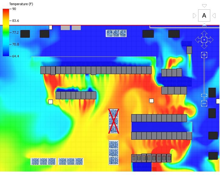
Presentation Narrative – Verizon SMARTS Data Center Design Phase 1

APPENDICIES

APPENDIX 1 – Air Temperature at 40” AFF For Option 1 Normal Operation

Project Number 20.14008.00                                                  Issue for Bid and Permit
31 July 2014                                     Page 15
Presentation Narrative – Verizon SMARTS Data Center Design Phase 1

APPENDIX 2 – Air Temperature at 40” AFF For Option 1 Failure Operation

Project Number 20.14008.00                                                  Issue for Bid and Permit
31 July 2014                                     Page 16
Presentation Narrative – Verizon SMARTS Data Center Design Phase 1

APPENDIX 3 – Air Temperature at 40” AFF For Option 2 Normal Operation

Project Number 20.14008.00                                                  Issue for Bid and Permit
31 July 2014                                     Page 17
Presentation Narrative – Verizon SMARTS Data Center Design Phase 1

APPENDIX 4 – Air Temperature at 40” AFF For Option 2 Failure Operation

Project Number 20.14008.00                                                  Issue for Bid and Permit
31 July 2014                                     Page 18
SMARTS MEP SCOPE - Liberty
Comments
2014 Mar 31
SMARTS MEP SCOPE - Liberty
Comments - In Row Option
2014 APR 09
PROJECT: VZ SMARTS Phase II                                  DATE: 25 June 2014
PROJECT NUMBER: 20.14008.00                                 PREPARED BY: N. Jabs
BUILDING/AREA: Cooling Load Calculation                        PAGE #: 1 of 2

Purpose:            1. Determine the total heat load for the SMARTS data center area.

Assumptions:        1. Rack equipment heat load is based upon: Rack quantity and size
                    2. Lighting load is assumed to be 1 watt per square foot in accordance with ASHRAE 90.1
                    3. Building exterior wall heat transfer coefficient is assumed to be:   0.09 BTU/(hr∙°F∙ft²)
                    4. Building roof heat transfer coefficient is assumed to be:      0.05 BTU/(hr∙°F∙ft²)
                    5. Weather data is based upon ASHRAE conditions listed for Baltimore, MD;
                       Outdoor Design Weather Conditions:             94 °F dry bulb
                                                                    74.9 °F wet bulb
                    6. Solar load through roof is assumed to be an additional 20 degrees added to space;

Design Criteria:         1. Rack Equipment Information
                             → 31 rack positions (South)
                             → 10 kW per rack
                             →    4 rack positions (North)
                             →    3 kW per rack

                         2. Space Information
                             → 3265 square feet of area
                             → 14 feet of exterior wall height
                             → 67 linear feet of exterior wall
                             → 75 °F dry bulb setpoint

Equations:         Rack Equipment Load: [(Rack Quantity)*(Rack kW)]*3413
                                                      1000

                   Lighting Load:     (Space Area)*(Lighting Watts/SF)*3.413
                                                       1000

                   Wall Skin Load: (Wall U‐factor)*(Wall Height)*(Wall Length)*(Outdoor Temp ‐ Space Temp)
                                                                     1000

                   Roof Skin Load: (Roof U‐factor)*(Space Area)*(Outdoor Temp + 20 ‐ Space Temp)
                                                                1000

Calculations:
        Heat Load

                          This document is the property of Liberty Engineering, LLP and is not to be distributed to parties
                                          without the prior written consent of Liberty Engineering, LLP.
                                                          CONFIDENTIAL PROPRIETARY
PROJECT: VZ SMARTS Phase II DATE: 25 June 2014
PROJECT NUMBER: 20.14008.00 PREPARED BY: N. Jabs
BUILDING/AREA: Cooling Load Calculation PAGE #: 2 of 2
Cooling Load (MBH)
Sensible Latent
Rack Load 1099.0 n/a
Lighting Load 11.1 n/a
Wall Skin Load 1.6 n/a
Roof Skin Load 6.4 n/a
CRAH unit fans 0.0 n/a ← CRAH Fans load already accounted for in capacity
Space Total: 1118.1 0.0
This document is the property of Liberty Engineering, LLP and is not to be distributed to parties
without the prior written consent of Liberty Engineering, LLP.
CONFIDENTIAL PROPRIETARYYou can also read