Casing design (temperature-base) of the K well in 'NPY' geothermal field-Indonesia
←
→
Page content transcription
If your browser does not render page correctly, please read the page content below

IOP Conference Series: Materials Science and Engineering

PAPER • OPEN ACCESS

Casing design (temperature-base) of the K well in ‘NPY’ geothermal
field-Indonesia
To cite this article: K Pudyastuti et al 2021 IOP Conf. Ser.: Mater. Sci. Eng. 1098 062026

View the article online for updates and enhancements.

                                This content was downloaded from IP address 46.4.80.155 on 02/08/2021 at 16:35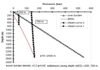
The 5th Annual Applied Science and Engineering Conference (AASEC 2020)                                                   IOP Publishing
IOP Conf. Series: Materials Science and Engineering              1098 (2021) 062026           doi:10.1088/1757-899X/1098/6/062026

Casing design (temperature-base) of the K well in ‘NPY’
geothermal field - Indonesia

                     K Pudyastuti1,*, N P Yufi1, M Djumantara1, A Hamid1, A Anugrahadi1 and A
                     Ashadi2
                     1
                         Petroleum Engineering Department, Trisakti University, Jakarta, Indonesia
                     2
                         KS Orka Renewables, Jakarta, Indonesia

                     *krispudyastuti@trisakti.ac.id

                     Abstract. This study explains the casing design for the K well in geothermal field, that involve
                     high temperature of wellbore about 200 OC – 300 OC. In the wellbore, elevated temperature
                     generates stress that occurs in the casing material, cause casing installed in the wellbore to
                     expand and shrink, and ultimately failure at a certain temperature conditions point. This failure
                     will change the production casing in length, as well as the well integrity. The casing design for
                     geothermal well must consider high temperature first, because the thermal effect on the casing
                     strength, resistance and burst, that cause the maximum joint strength of the casing decreases,
                     and leads to the collapse of the well. This study concludes that the design of geothermal well
                     casing configuration which is suitable for the K well are casing grade L80 for surface section,
                     casing grade S95 for production section, and grade S95 for slotted liner section. which agreed
                     with the design factors for the temperature maximum of plastic deformation i.e. 599.26 F,
                     667.6 F, and 852.36 F for respectively sections: surface, production, and liner depths. This
                     study also gives a benefit, i.e. recommendation for the field similar characteristics with the K
                     well – Indonesia. Pore and fracture or overburden pressure gradients, is a determinant in casing
                     shoe depth selection, the depth where temperature variation, play role in decreasing the
                     strength of casing material. It must be a major concern. Author suggest a reservoir
                     geomechanics studies on pore and fracture pressures gradient on the reference geothermal well,
                     may provide a comparison in casing depth selection based on resistivity logs analysis besides
                     BPCD.

1. Introduction
By any change in temperature to a material, a thermal stress is created. Geothermal wellbore
temperatures in high temperature field, with reservoir temperature of 250 – 300 OC and high enthalpy
1000 – 2800 kJ/kg [1], not only causes the decrease of casing materials yield strength, but also leads to
the change of casing materials elastic modulus and coefficient of thermal expansion. Casing materials
modulus of elasticity decreases linearly with the rise of temperature, while its thermal expansion
coefficient increases with the rise of temperature [2]. Besides calculating the value of the load
parameters that occur in each section of the casing to be installed in the well, it is also necessary to
consider the influence of temperature variation on the above parameters, so that the design is safe
against loads, and the influence of high temperatures. An example is the high temperature geothermal
well with the highest wellhead temperature measured was 450°C [3] at pressure around 144 bar [4],
has caused the production casing was severely damaged by multiple coupling failures and casing
collapse. This concluded the elevated well bore temperature will increase the load on the casings.
              Content from this work may be used under the terms of the Creative Commons Attribution 3.0 licence. Any further distribution
              of this work must maintain attribution to the author(s) and the title of the work, journal citation and DOI.
Published under licence by IOP Publishing Ltd                          1
The 5th Annual Applied Science and Engineering Conference (AASEC 2020) IOP Publishing
IOP Conf. Series: Materials Science and Engineering 1098 (2021) 062026 doi:10.1088/1757-899X/1098/6/062026
2. Methods
This study aims to determine the grade of the casing strength, safe from the loads and temperatures.
Thermal effect on casing design of geothermal well, based on thermally induced axial and radial
stress, and plastics deformation. The data used are hydrostatics or pore and fracture or overburden
pressure gradients of the reference well in the NPY geothermal field. There are 6 (six) steps of work in
this study.
First, determining the casing shoes depth based on hydrostatic and overburden pressures gradient.
Minimum depth of casing (according to the New Zealand code of practice 1991 [5]), is determined by
the way of extending the hydrostatic pressure up the well until it intersects the overburden pressure
line, This is commonly called BPDC (boiling point-depth curve) approach. By repeating the
procedure, then casings depth for conductor, surface, production and liner can be determined. Second,
plastic deformation analysis: finding the maximum temperature for plastic deformation obtained from
the intersection of the yield strength and thermal stress lines at formation’s temperature range. The
maximum temperature for plastic deformation, i.e. conditions of plastic deformation when thermal
load no longer caused a strain process after passing this temperature. The material has exceeded its
yield strength maximum, and at the same time its compressive stress value remain constant, although
the temperature continues to increase effectively [6,7]. Third, calculating the percentage of yield
strength reduction at formation's temperature for the each casing sections. Forth, Design Factor (DF)
analysis i.e. Yield Strength Reduction divided by Adjusted Loads, to find the casing strength which
has been in plastic deformation condition (reduction yield strength). Fifth, calculating the thermal
stress of the casing which has been in a plastic deformation condition. Sixth: casing grade selection
based on the DFs.
3. Geothermal well casing configuration and casing depth selections
The initial stage in well casing design is casing configuration determination. The configuration
typically is divided in three sections [8], namely surface or conductor (the largest diameter), anchor or
intermediate that support success that supports successive wellhead, and production or reservoir
section. The depth of each section should be chosen on the basis of the expected depths, and
conditions (temperature and pressure) of production fluids. Determination of the expected depth for
each section is influenced by drilling engineering, and geoscience information such as pore pressure
and fracture pressure gradients, as well as the depth of the top reservoir.
Figure 1. An example of pore pressure and Figure 2. An example of pore pressure and
fracture gradients used in casing depth overburden gradients used in casing depth
selection [9]. selection by New Zealand code of practice [5].
2The 5th Annual Applied Science and Engineering Conference (AASEC 2020) IOP Publishing
IOP Conf. Series: Materials Science and Engineering 1098 (2021) 062026 doi:10.1088/1757-899X/1098/6/062026
Figure 1 and 2 are example of the selection of casings shoe depth for each section (surface,
production, liner) based on pore pressure, and overburden or fracture pressures gradient.
4. Geothermal casing design (temperature base)
The major considerations in designing geothermal well casing is temperature. There are different
parameter need special consideration due to elevated temperature. Aside from the yield strength
reduction consideration, the two additional design criteria that need to be included are thermally
induced axial stress and plastic deformation. Besides, selection of the casing connection is also
critical. The connection should have the strength to withstand the compressive and tensile stresses
generated when exposed to high temperature.
4.1. Thermally induced axial stress
Once the casing is cemented, thermal expansion resulting from elevated temperature is restricted
because of creating axial compressive stress within the casing string. The maximum temperature
change of the well occurs during throttled (killing) operations. In geothermal wells, wellbore
temperatures can reach as high as about 600 °F (315.6 OC) when throttled and as low as 80 °F (26.7
O
C) when killed. With the high temperature change, material properties of casing should be
investigated for stress-temperature relationship to prevent casing failure.
Axial strain (z) is introduced when casing is subjected to a change in temperature, which is related
to coefficient thermal expansion. When the casing is cemented in place, the induced strain is converted
to stress, which is related to Young’s modulus elasticity.
Liu Xiao-gang et al. [10] discovered that the yield strength, coefficient of thermal expansion, and
modulus of elasticity of N80 change with temperature variation. Table 1 shows that under elevated
temperature, casing grade N80’s yield strength and its modulus of elasticity is reduced progressively
with a status of linear relationship. Noted that N80’s coefficient of thermal expansion is observably
enlarged along with the temperature raising [11].
Table 1. Physical properties of steel-grade N80 under temperature range from 20 to 300 deg.Celsius.
Temperatures Degrees C 20 100 150 200 250 300
Yield Strength (M.Pa.) 600.46 583.24 572.48 561.72 550.96 540.20
Elasticity Modulus (G.Pa.) 208.09 287.62 174.82 162.03 149.23 136.44
Thermal expansion coefficient, (m/(m℃)×10-6) 0.66 14.50 20.35 24.03 25.56 24.94
4.2. Yield strength reduction and casing grade selection
The weight and grade of casing to be used for each section will be dependent on the burst rating,
collapse resistance, tensile strength, thermal stress, and corrosion resistance requirements dictated by
the design criteria, geologic environment and operating conditions. In general, the burst rating,
collapse resistance and tensile strength of casing are linearly proportional to the yield strength of the
material. For certain conditions where the ratio of the pipe diameter to the wall thickness is high, the
collapse rating is no longer linearly proportional to the yield strength [11]. Various casing
manufacturers have their own tables for yield strength degradation due to temperature which the
designer may opt to use. Casing Yield Strength Degradation provided by Grant Pride Co – TCA
shown in Table 2.
4.3. Plastic deformation
The concept of plastic deformation design for casing has many applications in geothermal well design.
For example, if tieback casing cemented at 100°F (37.8 OC) was subjected to flowing temperature of
550°F (287.8 OC), the theoretical thermally induced compressive stress on the casing would exceed the
yield strength if L-80 casing was used. However, once the casing reaches the yield point, the
3The 5th Annual Applied Science and Engineering Conference (AASEC 2020) IOP Publishing
IOP Conf. Series: Materials Science and Engineering 1098 (2021) 062026 doi:10.1088/1757-899X/1098/6/062026
compressive stress remains constant while the temperature continues to increase effectively shortening
the length of the casing. When the casing is cooled to 80°F (26.7 OC) (quenching) after yielding, the
casing will be shorter that its original length and tensile stress will be generated as the temperature
decreases.
Table 2. Casing yield strength degradation by Grant Pride Co.
Temperature Degrees F Standard API Casing Grade
K-55 N-80 L-80 C-80 C-95 T-95
300 0.875 0.875 0.875 0.925 0.875 0.925
400 0.830 0.830 0.830 0.890 0.830 0.90
500 0.780 0.780 0.780 0.860 0.780 0.860
600 0.725 0.725 0.725 0.825 0.725 0.825
Theodoriu et.al [12] has calculated the material yield strength induces thermal stress, for common used
grades of casing. The result is shown in Table 3. It concluded that the temperatures in any higher
enthalpy geothermal well will cause plastic deformation even in casing strings made of high-grade
steel.
Table 3. The material yield strength induces thermal stress, for common used grades of casing.
Grade J-55 N-80 P105 P110
Temperature change (degrees C) 157 222 286 310
Temperature-corrected yield strength (MPa) 392 553 712 771
4.4. Safety factor
There are recommended safety factors for thermally induced axial stress and plastic deformation are
shown in Table 4.
Table 4. Safety factor for thermal induced stress, and plastic deformation [11].
Safety Factor
Thermal Induced Stress 1.0
Plastic Deformation (Maximum Tensile Load) 2.0
5. Parameters used
The parameters used for burst, collapse, tension and thermal stress calculations are derived from the
characteristics of the reference well, casing material and mud properties, shown in Table 5.
Table 5. The parameters used for burst, collapse, tension, and thermal stress calculation.
The Reference Well Casing Material Mud Properties
Gf, Fracture pressure Gradient [psi/ft] Collapse rating, [psi] Mud Weight, [Sg], [ppg]
Gob, Overburden pressure Gradient, [psi/ft] Body Yield, [lbs] Wa, [ppf]
Depth @Casing Shoe, [m] Internal Yield pressure, [psi] Collapse Rating, [psi]
3
Rock Formation Density (andesite), [g/cm ] Joint Strength [lbs] Cement Density, [ppg]
Rock Formation Density (granodiorite), [g/cm3] Strength Casing, [psi]
Temperature and pressure profile OD, outer diameter, [inch]
ID, inside diameter, [inch]
4The 5th Annual Applied Science and Engineering Conference (AASEC 2020) IOP Publishing
IOP Conf. Series: Materials Science and Engineering 1098 (2021) 062026 doi:10.1088/1757-899X/1098/6/062026
6. Steps of the study and result
Step-1: Casing shoe depth selection for the well casing configuration, referred to hydrostatic and
overburden (soil) pressure gradients of the reference well in the NPY geothermal Field [13]. The
casing diameters used in this study is as follow: conductor 30", surface 20", production 13 3/8", liner
10 3/4".
The result are: casing liner shoe depth of 2100 m TVD, production casing string shoe at depth of
1200 m TVD, intermediate or anchor casing string shoes at depth of 600 m TVD.
Step-2: By referring the well temperature profile, calculating the thermal stresses due to elevating
temperatures ranges from : a) 200 OC to 315 OC at the casing surface casing shoe depth, b) 200 OC to
370 OC at the production casing shoe depth, c) 200 OC to 480 OC at the liner casing shoe depth.
Step-3: Finding the maximum temperature of plastic deformation (T max) at the casing shoes
depth. This study found T max casing are 315.14 OC at the intermediate casing shoe depth, 353.14 OC
(667.6 OF) at the production casing shoe depth (Figure 3), and 455.75 OC at the liner casing shoe
depth.
Step-4: Found the yield strength reduction of 31.75%, 35.30%, and 35.30% for surface, production
and liner sections respectively.
Step-5: Found the Design Factor (DF): Burst [2.6 - 20”, 1.9 - 13 3/8”, 6.6 -10 ¾]; Collapse [1.4 –
20”, 1.4 – 13 3/8”, 1.7 – 10 ¾”]; Tension [5.8 - 20”, 3.7 – 13 3/8”, 1.7 – 10 ¾”]; Thermal Stress [3.0 -
20”, 2.0 – 13 13/8”, 2.2 - 10 ¾”].
Step 6. Found the selected casing grade based on DFs: L80 for surface section, S95 for production
section, S95 for slotted liner section.
90000.00 y = 109.36x - 7436.5 Thermal Stress
Pressure
70000.00
Yield Strength
Reduction
50000.00
Linear (Thermal
y = -49.875x + 98879 Stress)
30000.00
250 450 650 Linear (Yield
Temperature (Farenheit) Strength
Reduction)
Figure 3. Finding T max of plastic deformation at production casing shoe depth,
i.e. 667.6 OF or 353.1 OC, is a point of intersection between thermal stress line
and yield strength reduction line. [Nanda Pratama Yufi, his final assignment for
Petroleum undergraduate Program] [14].
7. Conclusion
The suitable casing grades for the K well are L80 surface casing, S95 production casing, and S95 liner,
which agreed with the design factors at temperature maximum of plastic deformation (T max) 599.26
O
F, 667.6 OF, and 852.36 OF respectively for surface section, production section, and liner depths.
8. Discussion
Since each geothermal field or reservoir has its own characteristics, this study will give a benefit, i.e.
recommendation of the casing design for the field, which has similar characteristics with the NPY
Field – Indonesia. Even though, the pore pressure and overburden pressures gradient, as a determinant
of the casing shoe depth selection, must be a major concern. In this study, pore pressure gradient is
hydrostatic pressure of the Boiling point-depth curve (BPDC) [15,16], has been used to determine
minimum casing depth. While, the pore and fracture pressure gradient applicable in oil and gas
industry is obtained by analysing resistivity logs and leak of test data (LOT) [9] instead of BPDC, then
5The 5th Annual Applied Science and Engineering Conference (AASEC 2020) IOP Publishing
IOP Conf. Series: Materials Science and Engineering 1098 (2021) 062026 doi:10.1088/1757-899X/1098/6/062026
the author suggests that this study need to be compared using geomechanics approach [17,18], to
obtain pore and fracture pressures gradient.
Acknowledgments
Authors acknowledge to Universitas Trisakti (Trisakti University), Faculty of Earth Technology and
Energy Research who supported to the study.
References
[1] Subir K. Sanyal, Classification Of Geothermal Systems – A Possible Scheme, Proceedings,
Thirtieth Workshop on Geothermal Reservoir Engineering Stanford University, Stanford,
California, January 31-February 2, 2005 SGP-TR-176.
[2] Zhang Pei-Feng, Thermal Stress Analysis of Casing String used in Enhanced Geothermal
System Well, Beijing Institute of Exploration Engineering, Beijing 100083, China. Journal
of Groundwater Science and Engineering Vol.4 No.2 Jun. 20.
[3] I. Thorbjornsson, G.S. Kaldal, B.S. Gunnarsson, Á. Ragnarsson, A New Approach to Mitigate
Casing failures in High-Temperature Geothermal Wells , ISOR – Iceland GeoSurvey,
Grensásvegur 9, 108 Reykjavik, Iceland ingo@isor.is . GRC Transactions, Vol. 41, 2017.
[4] Ingason, K., Kristjánsson, V. & Einarsson, K. 2014. Design and development of the discharge
system of IDDP-1.” Geothermics, 49, pp. 58-65.
[5] NZS, 1991: Code of practice for deep geothermal wells. Standards Association of New Zealand,
Wellington, NZ, New Zealand Standard 2403, 93 pp.
[6] Pazziuagan, D., 2000. Casing Stresses Caused by Temperature Change, PGE Internal Report.
[7] Sutikno Alamsyah, Production Casing Design -Chevron Geothermal Salak LTD, Proposal Kerja
Praktek (Job Training Proposal), 2014.
[8] Angelito Torres, Challenges of Casing Design in Geothermal Wells, Chevron Geothermal
Services Company, IADC/SPE-170480-MS.
[9] Jincai Zhang, Shang-Xian Yin, Fracture Gradient Prediction: An Overview and an Improved
Method, Pet. Sci. (2017) 14:720–730 DOI 10.1007/s12182-017-0182-1.
[10] LIU Xiao-gang, TAO Lin, et al. 2011. Optimal design of casing of high temperature and high
pressure well in Bohai Oilfield. Fault-Block Oil & Gas Field, 18(6): 787-789.
[11] Hagen Hole, Geothermal Well Design – Casing and Wellhead, Petroleum Engineering Summer
School Dubrovnik, Croatia. Workshop #26 June 9 – 13, 08.
[12] Teodoriu C, Falcone G. 2009. Comparing completion design in hydrocarbon and geothermal
wells: The need to evaluate the integrity of casing connections subject to thermal stresses.
Geothermics, 2009, 38(2): 238-246.
[13] Pertamina Geothermal Energy, Internal Report, 2019.
[14] Nanda Pratama Yufi, Final Assignment for Petroleum Undergraduate Program, Internal Report,
2019.
[15] Hossein-Pourazad, H., 2005: High temperature geothermal well design. Report 9 in: Geothermal
training in Iceland 2005. UNU-GTP, Iceland, 111-123.
[16] Abraham Wamala Khaemba, Well Design – Cementing Techniques and Well Work-Over To
Land Deep Production Casings in The Menengai Field, UNU-GTP Reports 2014 IS-108
Reykjavik, Iceland Number 17.
[17] Erwandi Yanto1, Fadiel Evan Marastio, Benedict Amandus Hananto, Dito Budi Sukarno, AN
Implication Of Stress Regime, Pore Pressure And Fracture Pressure Gradient To Enhance
Wellbore Stabilty of Geothermal Wells, Proceedings, The 6th Indonesia International
Geothermal Convention & Exhibition (IIGCE) 2018 Cendrawasih Hall, Jakarta Convention
Center Indonesia, September 5th-8th, 2018.
[18] M. Janis, J. Liu, and A. Ghassemi Sarkeys Energy Center, Norman OK, Reservoir
Geomechanics Model for EGS, GRC Transactions, Vol. 40, 2016.
6You can also read